2450 MHz / 2.45 GHz Microwave Generator Series

2450 MHz Microwave Generators for OEM and Process Systems

SDACME supplies magnetron-based continuous-wave 2450 MHz microwave generator systems in 6 kW、10 kW 和 15 kW rated power classes for OEM equipment, system integration and industrial process applications.

Generator selection is based on more than rated power. Waveguide interface, chamber or load conditions, reflected-power handling, control method, cooling capacity and site electrical conditions should be reviewed together before the final configuration is confirmed.

6 / 10 / 15 千瓦 Rated Power Classes
2450 MHz 2.45 GHz Frequency Family
CW Magnetron 微波源
  • ✓ External water cooling for current 6 / 10 / 15 kW models
  • ✓ Local touchscreen operation and RS485 communication
  • ✓ OEM integration and existing-source retrofit review
2450 MHz Series Industrial Microwave Source
15 kW 2450 MHz microwave generator power supply and microwave head
15 kW System Shown 2450 MHz Microwave Generator
Power Supply + Microwave Head
Current 2450 MHz Power Classes
2450 MHz Series Overview

What Is a 2450 MHz Microwave Generator?

A 2450 MHz 微v波发电机 converts electrical input power into controlled microwave energy in the 2.45 GHz frequency family for delivery to an engineered process load, applicator or chamber.

SDACME’s current 2450 MHz product family uses continuous-wave magnetron technology and is available in 6 kW、10 kW 和 15 kW rated power classes. The generator is selected as part of a complete microwave system, so power rating should be considered together with the microwave interface, load conditions, control requirements and cooling arrangement.

Microwave Generator, Power Supply and Microwave Head

In purchasing discussions, the terms microwave generator 还有 微波电源 are sometimes used interchangeably. For system engineering, however, the supply boundary should be defined more precisely.

该 power supply and control section provides electrical power conversion, operating control and protection functions. The microwave head contains the magnetron and microwave-generating structure. Additional microwave components are selected according to the model, installation and load conditions.

Power Supply & Control

Provides high-voltage power, operating control, monitoring and protection functions.

微波头

Contains the magnetron and microwave-generating structure connected to the microwave transmission path.

From Electrical Input to the Process Load

The exact supply scope varies by project, but a typical 2450 MHz microwave system can be understood through the following functional layers.

01 Power Supply & Control

Electrical conversion, microwave power control, monitoring and protection.

02 微波头

Magnetron-based microwave generation at the selected 2450 MHz power class.

03 Microwave Components

Waveguide, isolation, reflected-power handling, monitoring or tuning components as required.

04 Applicator / Chamber / Load

The customer or project equipment where microwave energy is coupled into the intended process.

Define the supply scope before quotation.

A 2450 MHz microwave generator is the microwave source. A complete reactor, applicator, process chamber or production line should not be assumed to be included unless those items are specifically listed in the technical proposal or quotation.

Next Selection Step Compare 6 kW, 10 kW and 15 kW

Review the three current 2450 MHz rated power classes before moving into detailed integration requirements.

Compare Power Classes
2450 MHz Power Classes

Compare 6 kW, 10 kW and 15 kW 2450 MHz Microwave Generators

SDACME’s current 2450 MHz series covers three rated power classes: 6 kW、10 kW 和 15 kW. All three belong to the same continuous-wave magnetron product family, while the final generator configuration is selected according to the equipment, load and integration requirements.

Use the comparison below for initial model screening. Exact adjustable power range, frequency tolerance, dimensions, cooling conditions, communication details and interface configuration should be confirmed on the corresponding model specification before an order is finalized.
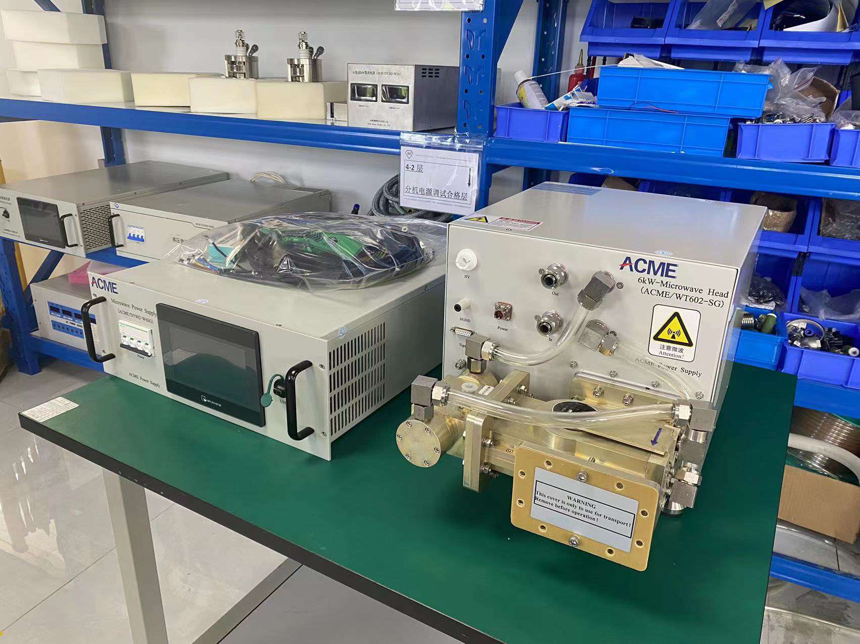
6 千瓦 2450 MHz
CW Magnetron
6 kW 2450 MHz microwave generator power supply and microwave head

6 kW 2450 MHz Microwave Generator

A 2450 MHz microwave source for equipment designed around the 6 kW rated power class, with generator control and microwave-head integration configured for the selected system.

  • 2450 MHz / 2.45 GHz frequency family
  • Continuous-wave magnetron source
  • External water cooling
  • Local touchscreen and RS485 on the current model
Selection focus

Evaluate when the target machine or process system is engineered around the 6 kW power class.

View 6 kW Generator
10 千瓦 2450 MHz
CW Magnetron
10 kW 2450 MHz microwave generator power supply and microwave head

10 kW 2450 MHz Microwave Generator

A 2450 MHz continuous-wave microwave source for systems designed around the 10 kW rated power class, with the electrical, control and microwave interfaces reviewed as part of equipment integration.

  • 2450 MHz / 2.45 GHz frequency family
  • Continuous-wave magnetron source
  • External water cooling
  • Local touchscreen and RS485 on the current model
Selection focus

Evaluate when the target machine or process system is engineered around the 10 kW power class.
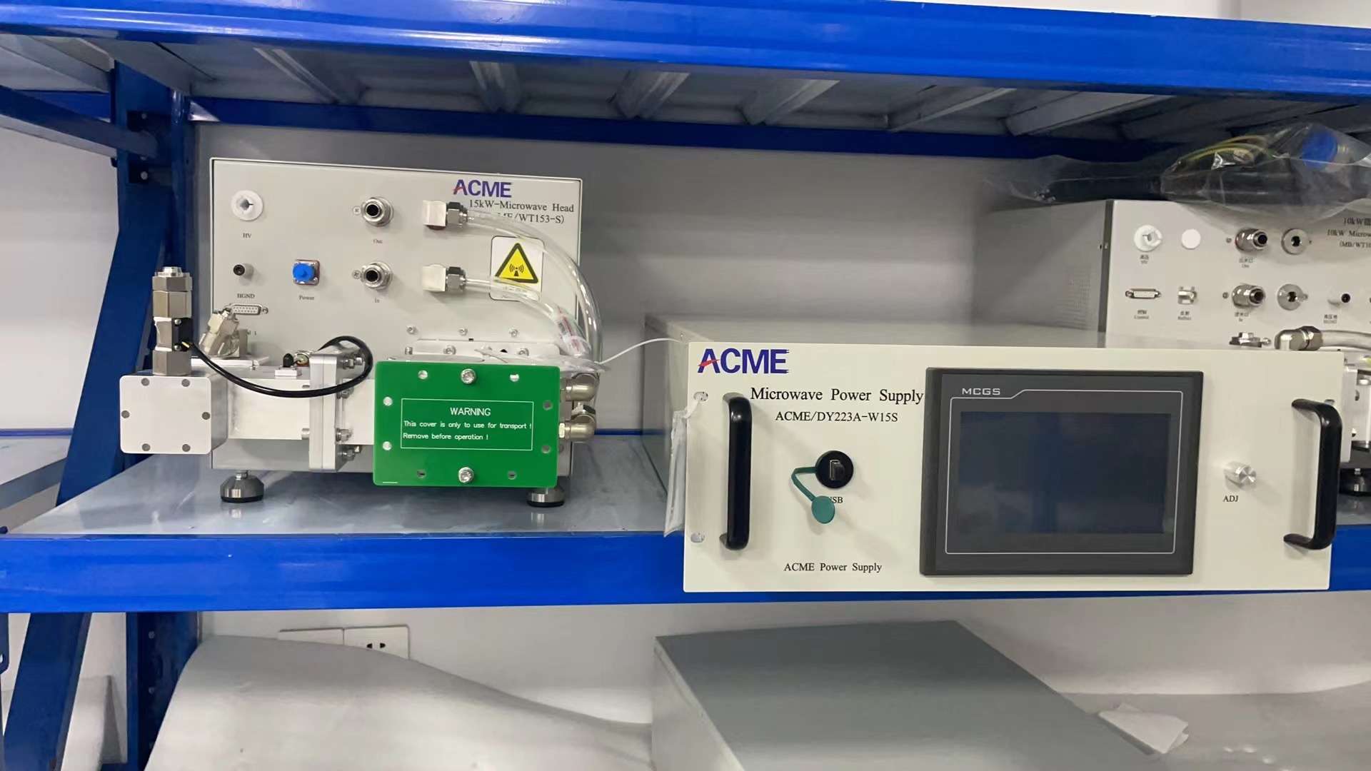
View 10 kW Generator
15 千瓦 2450 MHz
CW Magnetron
15 kW 2450 MHz microwave generator power supply and microwave head

15 千瓦 2450 MHz 微波发生器

A higher-power member of the current 2450 MHz family for equipment designed around the 15 kW rated power class, with model-specific cooling, interface and protection requirements.

  • 2450 MHz / 2.45 GHz frequency family
  • Continuous-wave magnetron source
  • External water cooling
  • Local touchscreen and RS485 on the current model
Selection focus

Evaluate when the target machine or process system is engineered around the 15 kW power class.

View 15 kW Generator

What the Three Power Classes Have in Common

The 6 kW, 10 kW and 15 kW models are part of the same 2450 MHz product family, allowing system designers to evaluate different rated power levels within a common microwave-source architecture.

2.45
2450 MHz Frequency

All three models operate within the 2.45 GHz microwave frequency family.

CW
Continuous-Wave Output

Current models use continuous-wave magnetron microwave-source architecture.

HMI
本地控制

Current models provide local operating interfaces for generator control and monitoring.

485
Equipment Communication

RS485 communication supports integration with customer equipment on current models.

Power rating is only the first filter.

Do Not Select a Generator by kW Alone

A higher microwave power rating does not automatically mean a better process result. The correct generator must also match the chamber or load, microwave coupling, reflected-power conditions, waveguide interface, control requirements, cooling capacity and site electrical conditions.

Four Conditions to Review Together

01 所需微波功率

Define the target power from the existing equipment, chamber or process-system engineering basis.

02 Waveguide & Load

Review flange geometry, coupling, load behavior and expected reflected-power conditions.

03 Control & Integration

Confirm local or remote operation, communication, interlocks and equipment interface requirements.

04 Cooling & Site Utilities

Verify external cooling capacity, site electrical input and model-specific installation conditions.

Need help choosing? Move from Power Class to Engineering Selection

The next section explains how to screen 6 kW, 10 kW and 15 kW using actual equipment and integration conditions.

How to Choose
Engineering Selection Guide

How to Choose Between 6 kW、10 kW 和 15 kW

Once 2450 MHz / 2.45 GHz has been confirmed, the next step is to determine the required microwave power class from the equipment and load conditions—not from a simple assumption that more power is always better.

For a new OEM machine, selection normally starts from the chamber, applicator or process-system engineering basis. For a replacement project, the existing generator power, waveguide connection, control interface and cooling conditions provide the most useful starting information.

First Selection Rule

Start With the Required Microwave Power, Not With the Largest Available Generator

The initial 6 kW, 10 kW or 15 kW candidate should come from the microwave-power requirement of the target machine, existing source or system design. After that first filter, the electrical, RF, control and cooling interfaces must be checked before the generator is confirmed.

Four Engineering Checks Before Model Confirmation

These four checks help narrow the series from a general 2450 MHz requirement to a technically reviewable 6 kW, 10 kW or 15 kW configuration.

01

Define the Power Requirement

Identify the power class specified by the existing generator, equipment design, chamber or microwave process-system engineering basis.

  • Existing generator rated power
  • New equipment design requirement
  • Required operating power range
  • Planned future operating margin
02

Check the RF Interface & Load

Verify how microwave energy will leave the generator and enter the applicator, chamber or existing microwave transmission line.

  • Waveguide and flange geometry
  • Coupling arrangement
  • Load and startup conditions
  • 反射功率管理
03

Confirm Control Integration

Define how the generator will be operated and how it should communicate with the customer’s machine or supervisory control system.

  • 本地或远程操作
  • RS485 communication
  • Interlock requirements
  • Project-specific signals
04

Verify Cooling & Site Utilities

Confirm that the installation can support the selected model’s electrical input and external water-cooling requirements.

  • Site electrical input
  • Cooling-water capacity
  • Model-specific cooling circuits
  • Installation and service space

New OEM System or Existing-Source Replacement?

New OEM

Start From the Equipment Design

For a newly designed machine, define the microwave requirement together with the chamber, coupling, control architecture and site utilities.

01What microwave power does the equipment design require?
02How will the microwave head connect to the chamber?
03What control and communication functions are required?
04What cooling and electrical utilities are available?
Replacement / Retrofit

Start From the Existing Source

For replacement projects, the existing generator and machine interfaces provide the most useful technical reference for model screening.

01What are the existing power and frequency ratings?
02What waveguide and flange connection is installed?
03What control, communication and interlocks are used?
04What are the existing electrical and cooling connections?

Use 6 / 10 / 15 kW as Candidate Classes

The series power classes should be treated as engineering candidates. The required or existing equipment power determines where the review starts; interface compatibility determines whether that candidate can become the final configuration.

Higher rated power does not guarantee a better process result.

Deposition rate, plasma behavior, heating performance, material quality, throughput and other application results depend on the complete equipment and process system. Generator power is only one part of that system.

Information That Makes Selection Faster

Sending the following information helps reduce back-and-forth and allows the first technical response to focus on the correct power class and integration scope.

✓

Application or equipment type

✓

Required or existing microwave power

✓

New OEM or retrofit project

✓

Chamber or process-load information

✓

Waveguide / flange drawings or photos

✓

Site electrical input

✓

控制与通信要求

✓

Available cooling-water conditions

After Power-Class Screening Confirm What the Generator System Must Include

The next section separates the microwave power supply, microwave head, microwave-system components and customer process equipment.

Review System Scope
Generator Architecture & Supply Scope

What Makes Up a 2450 MHz Microwave Generator System?

A 2450 MHz microwave generator system combines the power supply and control section, microwave head and the microwave transmission components needed to deliver controlled microwave energy to the customer’s equipment.

The final system configuration depends on the selected 6 kW, 10 kW or 15 kW generator, waveguide interface, load conditions, reflected-power requirements, control architecture and the agreed project scope.

Power Supply, Control and Microwave Head

The power-supply section converts the incoming electrical power and provides the operating, monitoring and protection functions required by the microwave source.

The microwave head contains the magnetron and associated microwave-generating structure. From the microwave head, energy enters the waveguide transmission path and is delivered toward the applicator, cavity or process chamber.

01
Power Supply & Control

Electrical power conversion, generator operation, monitoring and protection.

02
微波头

Magnetron-based microwave generation and connection to the microwave transmission system.
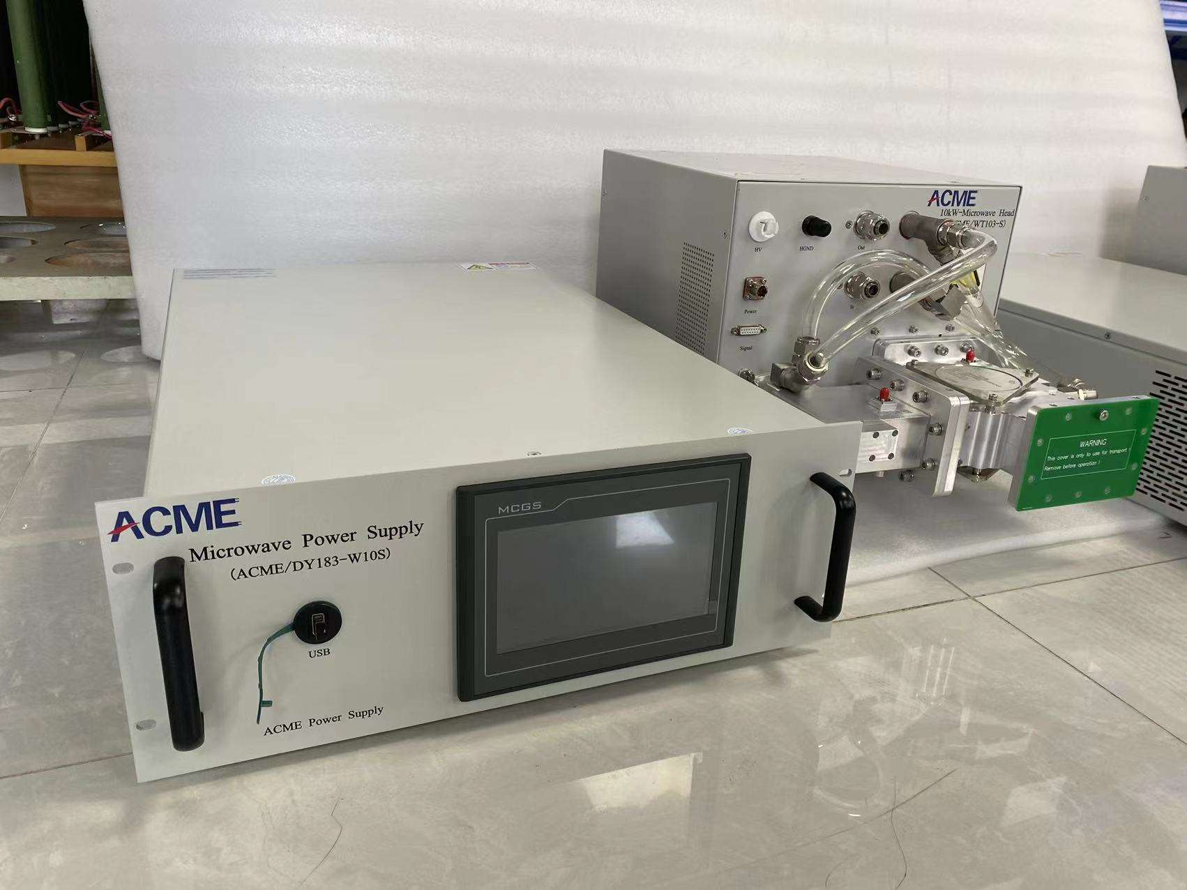
2450 MHz Generator Hardware 10 kW System Shown
10 kW 2450 MHz microwave generator power supply and microwave head
微波电源 + 微波头 Representative 2450 MHz generator hardware. Final configuration is selected according to the project.

From Electrical Input to the Process Load

Looking at the system as a complete microwave-energy path helps define the correct generator configuration and identify the interfaces that must be reviewed during equipment integration.

01 Power Supply & Control

Converts site electrical input and manages generator operation.

02 微波头

Generates continuous-wave 2450 MHz microwave energy.

03 微波传输

Routes, protects, monitors or tunes microwave energy according to the system design.

04 Applicator / Chamber / Load

Couples microwave energy into the customer’s intended equipment or process.

Generator Platform

Core Generator Functions

These functions form the basic microwave-source architecture of the current 2450 MHz generator family.

✓
Electrical Power Conversion

Converts the available electrical input for operation of the microwave source.

✓
Microwave Generation

Continuous-wave magnetron-based generation in the 2450 MHz frequency family.

✓
Generator Control & Protection

Operating control, monitoring and model-specific generator protection functions.

项目配置

Microwave Transmission Components

The transmission path is configured according to the selected generator, interface and load conditions.

+
Isolation & Reflected-Power Handling

Components can be selected according to the required microwave-source protection strategy.

+
波导组件

Waveguide sections, transitions and mechanical interfaces are matched to the installation.

+
Tuning & Monitoring

Tuning or monitoring components can be configured where required by the microwave circuit.

Equipment Defined According to the Project Scope

The microwave generator forms the microwave-source section of the system. Process equipment, utilities and plant-level controls can be defined separately according to the application and the agreed project scope.

Process Chamber / Reactor

The applicator, cavity or process chamber is defined according to the application and system design.

Process Utilities

Vacuum, gas, material handling and other process utilities are configured according to the application requirements.

Plant-Level Controls & Automation

The generator control interface can be integrated with customer equipment or higher-level automation according to the agreed control scope.

Compare microwave generator quotations by supply scope—not rated power alone.

Two 2450 MHz microwave generator quotations can have the same rated power but include different waveguide components, protection functions, control interfaces and project accessories. Reviewing the detailed supply scope helps ensure an accurate technical and commercial comparison.

Define the Interfaces Around the Generator

Providing these project details allows the generator package and supporting microwave components to be reviewed more accurately.

✓

Required 6 / 10 / 15 kW power class

✓

波导和法兰接口

✓

Applicator or chamber connection

✓

Expected load and reflected-power conditions

✓

控制与通信要求

✓

Cooling and site electrical conditions

Next Integration Step Confirm the Waveguide and Mechanical Interface

The next section covers waveguide connection, impedance matching, flange geometry and integration with the customer’s applicator or chamber.

Review Waveguide Integration
Waveguide & Equipment Integration

Match the Microwave Generator to the Waveguide, Load and Chamber

A 2450 MHz microwave generator cannot be selected by electrical power alone. The microwave transmission interface between the generator and the customer’s equipment must also be checked before the final configuration is confirmed.

Waveguide geometry, flange connection, coupling arrangement, reflected-power conditions and any required tuning or monitoring components should be reviewed together with the 6 kW, 10 kW or 15 kW power class.
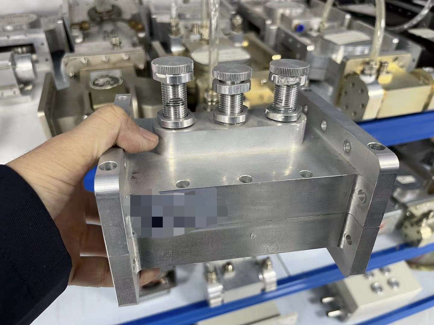
Waveguide Tuning Component Project-Configured Hardware
Three-probe waveguide tuner used for microwave impedance matching
Three-Probe Waveguide Tuner Used where the microwave transmission system requires impedance-adjustment or matching capability.

Why the Load Matters

Microwave power leaves the generator through the microwave transmission system and is coupled into the customer’s load. When the load is not well matched, part of the microwave energy can be reflected back toward the source.

Depending on the system architecture, waveguide tuning, isolation, reflected-power handling or monitoring components can be used to support stable integration between the generator and the process equipment.

01
Match the Mechanical Interface

Confirm the actual waveguide and flange geometry before manufacturing or ordering interface parts.

02
Review Reflected Power

Expected load variation and reflected-power conditions influence the required microwave-system components.

03
Configure Tuning as Required

Tuning hardware is selected according to the actual microwave circuit and is not assumed to be identical for every project.

Review the Complete RF Path, Not Only the Generator

A practical integration review follows the microwave energy from the source to the final applicator or chamber. Each connection point can affect mechanical compatibility, reflected power and system configuration.

01 微波头

The microwave source connection where energy enters the transmission path.

02 Waveguide Path

Straight sections, bends, transitions or other transmission components selected for the installation.

03 Matching / Protection

Tuning, isolation, reflected-power handling or monitoring components where required.

04 喷雾器/室

The final load where microwave energy is coupled into the intended process.

Confirm These Details Before Finalizing the Connection

For an OEM or retrofit project, actual drawings and photographs are more useful than relying on a nominal waveguide description alone.

01
Waveguide Size

Confirm the actual transmission-line dimensions used by the existing or planned equipment.

02
Flange Geometry

Check bolt pattern, flange shape, orientation and connection dimensions.

03
Installation Orientation

Define microwave-head position, waveguide direction and available installation space.

04
Existing Components

Identify any installed circulator, tuner, directional coupler, water load or transition section.

05
Load Characteristics

Describe startup behavior, load variation and any known reflected-power conditions.

06
Chamber Connection

Confirm how microwave energy enters the applicator, cavity or process chamber.

New Equipment and Retrofit Projects Require Different Inputs

New OEM System Design the RF Interface Together

When the equipment is still being designed, the generator, waveguide path and chamber connection can be reviewed as one integration problem.

  • Provide chamber or applicator drawings
  • Define the generator installation position
  • Define required microwave transmission components
  • Review access for installation and maintenance
Replacement / Retrofit Match the Existing Mechanical Interface

For a retrofit, dimensional compatibility and the existing transmission path become critical because the new source must integrate with installed equipment.

  • Send existing generator nameplate information
  • Send waveguide and flange dimensions
  • Photograph installed microwave components
  • Identify modifications that are acceptable on site
Confirm the actual output interface for the selected model.

Waveguide and flange references may appear in technical documentation, but the final output connection should be confirmed from the selected generator configuration and project drawings. Do not rely on appearance alone when matching an existing installation.

What to Send for a Waveguide Compatibility Check

A small amount of dimensional information can eliminate many interface questions before quotation.

✓

Waveguide and flange dimensions

✓

Clear photos of the existing connection

✓

Existing microwave generator model

✓

Required 6 / 10 / 15 kW power class

✓

Installed waveguide components

✓

Chamber or applicator connection drawing

Next Engineering Layer Review Controls, Monitoring and Protection

After the microwave interface is defined, the next step is to confirm how the generator will be operated, monitored, protected and connected to the customer’s control system.

Review Controls
Controls, Monitoring & Protection

Operate the Generator Locally or Integrate It With Your Equipment

Current SDACME 2450 MHz microwave generators support local touchscreen operation 还有 RS485 communication, allowing the microwave source to operate as a stand-alone subsystem or as part of larger OEM equipment.

The exact control functions, displayed parameters, communication mapping, alarms and interlock logic are confirmed according to the selected 6 kW, 10 kW or 15 kW model and the customer’s integration requirements.

Touchscreen HMI for Operation and Status Review

The local HMI provides an operator interface for generator operation, operating-status review and fault information on the selected model.

For OEM systems, the local interface can also remain available for commissioning, maintenance and diagnostic work while the generator communicates with external equipment through the agreed control interface.

01
本地运营

Use the generator HMI for equipment setup, operation and service access.

02
运行状态

Review generator operating information and model-specific status indications.

03
故障信息

Generator faults and protection events can be presented through the local interface according to the selected configuration.
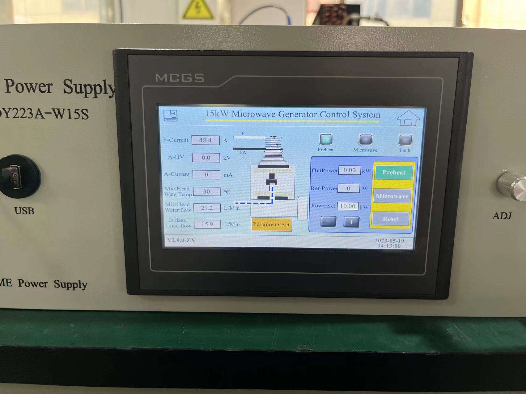
Local Control Interface 15 kW HMI Shown
15 kW 2450 MHz microwave generator touchscreen control interface
Microwave Generator Touchscreen HMI Screen layout and available functions depend on the selected generator model and configuration.

From Local Operation to OEM Machine Integration

The generator control system can be viewed in four functional layers: local operation, generator monitoring, communication and equipment-level interlocking.

01 本地 HMI

Operator access for generator setup, operation, status review and service work.

02 监控

Operating parameters, status information and model-specific fault indications.

03 RS485 通信

Provides a communication path between the microwave generator and customer equipment.

04 OEM Machine Control

Customer PLC, controller or supervisory system can coordinate generator operation through the agreed interface.

Local Control or Equipment-Level Integration?

The preferred control architecture depends on how the microwave generator will be used inside the customer’s equipment.

本地运营

Generator-Centered Control

Suitable when the microwave source is operated directly from its local interface during testing, commissioning or stand-alone equipment operation.

  • Local touchscreen access
  • Generator status review
  • Local operating commands
  • Maintenance and diagnostic access
OEM 集成

Machine-Centered Control

Suitable when the microwave source becomes one subsystem inside a larger machine and operation must be coordinated with the customer’s control sequence.

  • RS485 communication
  • Equipment-level operating sequence
  • Generator status exchange
  • Project-defined interlock logic

Generator Protection Must Match the Complete System

Microwave-source protection is not only an HMI function. It must work together with cooling conditions, the microwave transmission path, load behavior and the customer’s machine interlocks.

The selected generator model defines the available internal protection functions, while project-level interlocks define how the microwave source should respond to conditions in the surrounding equipment.

01
Generator Status

Internal operating and fault conditions are monitored according to the selected model.

02
冷却条件

Cooling-system conditions must support safe operation of the microwave source.

03
Microwave Load Conditions

Reflected-power and load behavior are considered when configuring the microwave system.

04
设备锁

Customer machine conditions can be incorporated into the agreed operating and safety logic.

Define the Communication Requirements Before Integration

RS485 is available on current models, but the required commands, status data and communication details should be defined according to the customer’s machine architecture.

✓

Local-only or external equipment control

✓

Required operating commands

✓

Status information required by the machine

✓

Alarm or fault information to be exchanged

✓

Machine and generator interlock requirements

✓

Customer controller or PLC information

Confirm communication and protection details for the selected model.

The 6 kW, 10 kW and 15 kW generators share the same overall control concept, but exact HMI pages, available parameters, communication mapping, alarm logic and protection thresholds should be confirmed from the corresponding technical documentation.

Next Installation Requirement Confirm Cooling and Site Conditions

The next section reviews external water cooling, installation space and site utilities required before the selected generator can be integrated into the customer’s equipment.

Review Cooling & Installation
冷却与安装

Plan Cooling and Site Utilities Before the Generator Is Installed

Current SDACME 2450 MHz microwave generators in the 6 kW、10 kW 和 15 kW classes require external water cooling. Cooling should be treated as part of the generator integration design rather than as a separate afterthought.

The required cooling capacity, water conditions, connection arrangement and number of cooling circuits depend on the selected generator model. Site electrical input, installation space and service access should also be confirmed before the final configuration is approved.
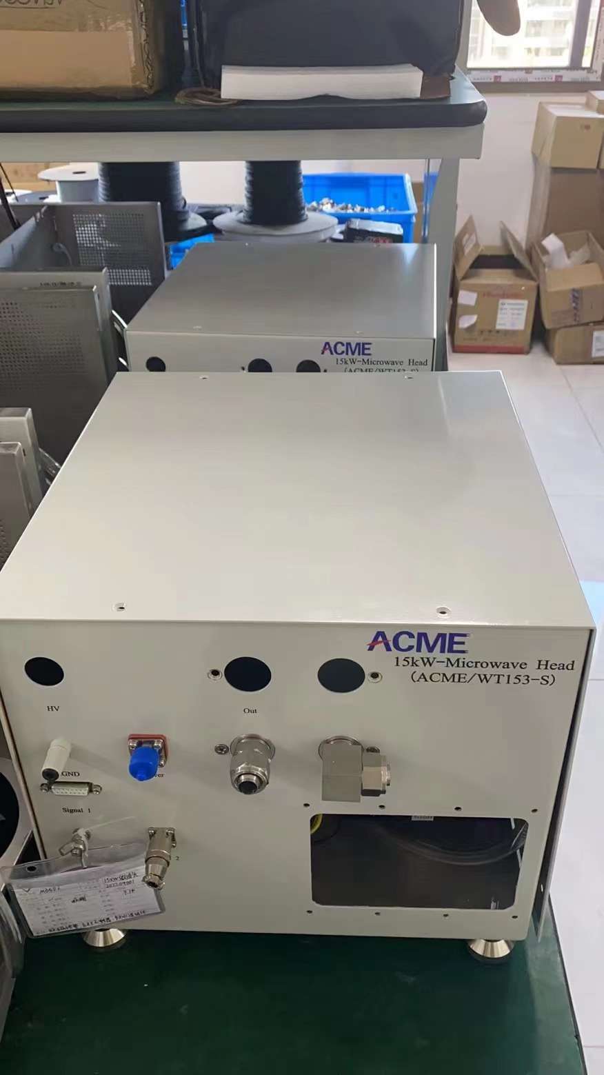
Microwave Head Cooling Connections 15 kW Hardware Shown
15 kW 2450 MHz microwave head cooling and interface connections
Microwave Head Cooling & Interface Connections The image shows a 15 kW configuration. Cooling-circuit arrangement and connection details are model-specific.

Cooling Conditions Must Match the Selected Generator

Microwave-generation hardware produces heat during continuous-wave operation. A stable external cooling system is therefore required to support the microwave head and other water-cooled components in the selected configuration.

The 15 kW system shown here uses multiple cooling connections, but this should not be treated as a universal piping layout for the 6 kW and 10 kW models.

01
确认冷却能力

Size the external cooling system for the selected generator model and operating conditions.

02
Confirm Water Conditions

Review required inlet conditions and cooling-water quality from the applicable model documentation.

03
Confirm Connection Layout

Verify hose, pipe and cooling-circuit connections before equipment installation.

Four Site Conditions to Check Before Installation

Cooling is only one part of the installation review. The electrical supply, equipment arrangement and service space should be checked at the same time.

01 Cooling Water

Confirm available cooling capacity, water condition, connection method and model-specific circuit requirements.

02 电力供应

Verify the site electrical input against the selected generator model before installation.

03 设备空间

Allow sufficient room for the power supply, microwave head, waveguide components and connecting services.

04 Service Access

Keep access available for inspection, cooling connections, electrical service and microwave-system maintenance.

Treat Cooling as Part of the Generator System

A practical cooling review follows the complete path from the customer’s cooling-water source to the microwave hardware and back to the return circuit.

01 Cooling Source

Customer chiller or suitable external cooling-water system.

02 Supply Connection

Water is routed to the required generator cooling circuits.

03 Microwave Hardware

Selected water-cooled components receive the required thermal management.

04 Return Circuit

Heated cooling water returns to the customer’s external cooling system.

Do Not Apply One Cooling Specification to All Three Power Classes

The 6 kW, 10 kW and 15 kW generators belong to the same 2450 MHz family, but their detailed cooling requirements should remain model-specific.

01
Flow Requirement

Confirm from the selected model specification rather than applying a family-wide value.

02
Cooling Circuit Count

Connection quantity and circuit arrangement can differ between generator configurations.

03
Connection Size

Pipe, hose and fitting details should be confirmed before site preparation.

04
水质状况

Required temperature, pressure and water-quality conditions should follow the relevant model documentation.

Plan the Generator Around the Machine Layout

The microwave power supply, microwave head and waveguide components do not have to occupy the same physical position. Their arrangement should be coordinated with the equipment structure, microwave path, cooling connections and service access.

A Power Supply Position

Allow suitable access for electrical connection, control wiring and maintenance.

B Microwave Head Position

Coordinate the microwave head with the planned waveguide and process-equipment connection.

C 冷却连接

Keep cooling hoses or piping accessible and avoid unnecessary routing complexity.

D Maintenance Space

Provide enough room for inspection, replacement and service of key microwave components.

Site Information to Provide

Supplying the basic utility and layout information early helps avoid changes after equipment manufacturing.

✓

Selected 6 / 10 / 15 kW generator class

✓

Available electrical supply

✓

Available external cooling system

✓

冷却水条件

✓

Equipment layout or installation drawing

✓

Available service and maintenance space

Use the selected model documentation for final cooling values.

The 2450 MHz series shares the requirement for external water cooling, but cooling-water flow, connection details, circuit arrangement and installation conditions should be confirmed for the specific 6 kW, 10 kW or 15 kW generator before site piping is finalized.

Next Selection Context Review Where 2450 MHz Generators Are Integrated

The next section introduces application and integration contexts for 2450 MHz microwave generators without treating the microwave source itself as a complete process machine.

Review Applications
Application & Integration Contexts

Where 2450 MHz Microwave Generators Fit Into Process and OEM Systems

SDACME 2450 MHz microwave generators can be integrated as microwave power sources in plasma, CVD, research and OEM process equipment where the system is engineered around the 2.45 GHz frequency family.

Application suitability depends on the complete system: chamber or applicator design, microwave coupling, target power, reflected-power conditions, control strategy and cooling arrangement must all be considered before selecting a 6 kW, 10 kW or 15 kW generator.

Four Common Ways the 2450 MHz Generator Is Used

These examples describe the role of the microwave source inside larger equipment. They do not imply that the generator alone performs the complete process.

CVD / Plasma

MPCVD System Integration

The microwave generator can provide the microwave energy required by an MPCVD reactor designed for 2450 MHz operation.

Generator Role 微波电源
  • Reactor and plasma chamber remain part of the complete MPCVD system
  • Waveguide coupling must match the reactor design
  • Microwave power is only one process variable
  • Final power class depends on equipment engineering
Microwave Plasma

Plasma Generation Systems

A 2450 MHz microwave source can be integrated into equipment designed to generate or sustain microwave plasma for the intended process.

Generator Role Plasma Energy Source
  • Plasma behavior depends on the complete reactor and process conditions
  • Coupling and reflected power must be reviewed
  • Generator control can integrate with machine logic
  • Cooling must support the selected operating condition
定制设备

Industrial OEM Process Equipment

Equipment manufacturers can integrate the microwave generator as one subsystem inside a larger industrial microwave machine.

Generator Role OEM微波子系统
  • Power class selected from equipment design
  • Mechanical and waveguide interfaces reviewed together
  • RS485 supports equipment-level integration
  • Supply scope can be matched to the OEM architecture
Research Systems

Research & Experimental Equipment

Universities, laboratories and equipment developers can integrate the generator into purpose-built experimental microwave systems.

Generator Role Controlled Microwave Source
  • Experimental chamber remains project-specific
  • Interface design depends on the research setup
  • Local HMI supports commissioning and operation
  • External control can support automated experiments

The Generator Supplies Microwave Energy— the Process System Determines the Result

A microwave generator provides controlled microwave power to the surrounding equipment. The actual plasma, deposition, heating or material-processing result depends on the complete process system and operating conditions.

01 微波发生器

Produces controlled 2450 MHz microwave energy.

02 Waveguide & Coupling

Transfers microwave energy toward the process equipment.

03 Chamber / Applicator

Couples microwave energy into the process environment.

04 Process Result

Depends on the complete equipment and process conditions.

What Determines Whether a 2450 MHz Generator Fits the Project?

Application type is only the starting point. The generator should be screened against the complete equipment design.

01 Frequency Requirement

Confirm that the target equipment is designed around 2450 MHz / 2.45 GHz operation.

02 Required Power Class

Determine whether the engineering basis points to the 6 kW, 10 kW or 15 kW class.

03 Chamber & Load

Review how the target chamber or applicator behaves as a microwave load.

04 Microwave Interface

Confirm waveguide, flange, coupling and reflected-power handling requirements.

05 Control Architecture

Define local operation, RS485 communication, interlocks and machine-level control.

06 Cooling & Utilities

Verify electrical input, external water cooling and available installation conditions.

Select the generator from equipment requirements—not from the application name alone.

Two systems described as “MPCVD”, “microwave plasma” or “industrial microwave equipment” can require different microwave power, interfaces, control functions and cooling arrangements. Application type should therefore be combined with actual engineering data during model selection.

Information to Send for Initial Evaluation

These details help determine whether the project should start from the 6 kW, 10 kW or 15 kW 2450 MHz generator.

✓

Application or equipment type

✓

Required 2450 MHz microwave power

✓

Chamber or applicator description

✓

Waveguide or flange information

✓

New OEM or replacement project

✓

Control and cooling requirements

Final Engineering Step Review OEM Integration, Retrofit and Model Selection

The next section brings the power class, microwave interface, controls, cooling and project scope together into one practical selection process.

Review OEM & Retrofit
OEM Integration & Retrofit

Turn Your Requirements Into a 2450 MHz Generator Configuration

Whether the project is a new OEM machine or a replacement of an existing microwave source, final selection should bring the power class, microwave interface, controls, cooling and supply scope together.

SDACME can review the available engineering information and identify a suitable 6 kW, 10 kW or 15 kW 2450 MHz generator configuration for further technical confirmation.

New OEM Integration or Existing-Source Replacement?

Both projects can use the same 2450 MHz generator family, but the information required for model selection is different.

New OEM Equipment

Design the Microwave Source Into the Machine

For a new system, the generator can be selected together with the equipment architecture rather than being forced to match an existing microwave-source layout.

01

Define the required 2450 MHz microwave power class.

02

Define chamber, applicator and waveguide arrangement.

03

Define generator control and machine communication.

04

Define external cooling and site electrical conditions.

Replacement / Retrofit

Match the Existing Equipment Interfaces

For replacement projects, the existing source and installed equipment provide the engineering reference for compatibility review.

01

Identify existing frequency and rated microwave power.

02

Check existing waveguide, flange and source connection.

03

Review controls, communication and equipment interlocks.

04

Review electrical input and cooling connections.

Five Steps From Inquiry to Generator Configuration

A structured review reduces uncertainty before detailed technical confirmation and quotation.

01 Define the Project

New OEM, system upgrade or replacement of an existing microwave source.

02 Confirm Power Class

Screen the requirement against the 6 kW, 10 kW or 15 kW 2450 MHz family.

03 Review RF Interface

Check waveguide, flange, coupling, load and reflected-power conditions.

04 Confirm Utilities & Controls

Review communication, interlocks, site electrical input and external water cooling.

05 Confirm Configuration

Define the generator model, microwave-system components and project supply scope.

What Should Be Checked When Replacing an Existing Generator?

Matching rated power alone is not enough for a practical replacement. Mechanical, electrical, control and cooling interfaces should be reviewed together.

01
Frequency & Power

Confirm existing operating frequency and rated microwave power.

02
波导接口

Check existing waveguide size, flange geometry and source orientation.

03
Mechanical Envelope

Review available installation space and existing equipment arrangement.

04
电力供应

Compare site electrical conditions with the proposed generator requirements.

05
Control Interface

Identify operating commands, communication, feedback and machine interlocks.

06
冷却连接

Review the existing cooling system and the selected model’s cooling requirements.

Send the Information You Already Have

A complete engineering package is not required for the first contact. Existing drawings, equipment photos and basic operating information can provide a practical starting point.

✓

Application or equipment type

✓

Required or existing microwave power

✓

Existing generator nameplate or model

✓

Waveguide and flange photos or drawings

✓

Chamber or applicator information

✓

网站电气状况

✓

可用的冷却系统

✓

Control / PLC integration requirements

What the Technical Review Helps Define

The objective is to move from a general “2450 MHz microwave generator” inquiry to a configuration that can be technically compared and quoted.

6 / 10 / 15 Generator Power Class

Identify the appropriate 2450 MHz generator class for detailed model confirmation.

RF Microwave Interface

Define the required waveguide connection and related microwave-system components.

I/O Control Interface

Define local operation, communication and equipment-level integration requirements.

H₂O 冷却与安装

Identify the model-specific cooling and site-integration conditions to confirm.

For retrofit projects, photos and dimensions are often as useful as a model number.

If the original microwave-source documentation is incomplete, clear photos of the nameplate, microwave head, waveguide flange, cooling connections and control interface can help establish the information needed for an initial compatibility review.

Before Sending Your Inquiry Review Common 2450 MHz Generator Questions

The FAQ section answers common questions about frequency, power selection, cooling, controls, waveguide integration, MPCVD use and replacement projects.

View FAQ
2450 MHz Microwave Generator FAQ

Common Questions About 2450 MHz Microwave Generators

These answers cover the most common questions about 2450 MHz / 2.45 GHz microwave generators, including power selection, MPCVD integration, waveguide compatibility, controls, cooling and replacement projects.

频率 2450 MHz / 2.45 GHz
Current Power Classes 6 / 10 / 15 千瓦
Source Type CW Magnetron
冷却 External Water Cooling
01 What is a 2450 MHz microwave generator?

A 2450 MHz 微v波发电机 is a microwave power source that converts electrical input into controlled microwave energy in the 2.45 GHz frequency family.

In an industrial system, the generator typically works with a microwave head, waveguide transmission components and an applicator, cavity or process chamber that couples the microwave energy into the intended load.

02 Is 2450 MHz the same as 2.45 GHz?

是的。 2450 MHz and 2.45 GHz describe the same nominal microwave frequency because 1000 MHz equals 1 GHz.

The two expressions are commonly used interchangeably when discussing industrial microwave equipment operating in the 2.45 GHz frequency family.

03 Should I choose a 6 kW, 10 kW or 15 kW generator?

Choose the power class from the actual microwave-power requirement of the equipment, not simply by selecting the highest available rating.

For new OEM equipment, the chamber, applicator and process system provide the engineering basis. For a replacement project, the existing generator rating is usually the first reference point.

Waveguide compatibility, load conditions, controls, cooling and site electrical conditions should then be checked before the final model is confirmed.

04 Are the 6 kW, 10 kW and 15 kW models solid-state generators?

没有。. The current SDACME 2450 MHz 6 kW, 10 kW and 15 kW series uses continuous-wave magnetron technology.

A solid-state microwave source is a different generator architecture and should not be assumed to have the same configuration as this product family.

05 Can a 2450 MHz microwave generator be used for MPCVD?

Yes, when the MPCVD system is designed for a 2450 MHz microwave source.

The generator supplies microwave energy to the MPCVD system, while the plasma reactor, chamber, waveguide coupling, vacuum system, gas system and process controls form other parts of the complete equipment.

The required 6 kW, 10 kW or 15 kW power class should be determined from the actual reactor and equipment design.

06 Does the microwave generator include a complete MPCVD machine?

没有。. A microwave generator is the microwave-source subsystem, not the complete MPCVD machine.

A complete MPCVD system normally involves additional equipment such as the reactor or chamber, microwave coupling components, vacuum equipment, gas delivery, process control and other application-specific systems.

07 Do 2450 MHz microwave generators require water cooling?

是的。 The current SDACME 6 kW, 10 kW and 15 kW 2450 MHz models require external water cooling.

The required water conditions, flow, connections and cooling-circuit arrangement are model-specific and should be confirmed before site piping or cooling-system preparation is finalized.

08 Can the microwave generator communicate with a PLC or OEM machine?

是的。 Current models support local touchscreen operation and RS485 communication for equipment integration.

The exact commands, status data, communication mapping and equipment interlocks should be defined according to the selected generator model and the customer’s control architecture.

09 What waveguide information is needed before ordering?

Provide the available waveguide dimensions, flange geometry, connection orientation and chamber or applicator interface.

For existing equipment, clear photographs and dimensional drawings of the installed waveguide connection are also useful. Final interface compatibility should be confirmed against the selected generator configuration.

10 What causes reflected microwave power?

Reflected power occurs when the microwave load does not fully absorb the incident microwave energy and part of that energy travels back toward the source.

Load behavior, coupling and impedance matching can influence reflected power. Depending on the system, isolation, monitoring, reflected-power handling and tuning components can be configured to support the microwave source.

11 Can SDACME replace an existing 2450 MHz microwave generator?

A replacement configuration can be evaluated when the existing system operates in the 2450 MHz frequency family and sufficient interface information is available.

The review should compare rated power, waveguide and flange geometry, installation space, electrical supply, cooling connections, control signals and communication requirements.

Existing generator nameplate information, drawings and photographs are useful starting materials.

12 What information should I send for generator selection?

For an initial model review, send the information already available for your project:

  • Application or equipment type
  • Required or existing microwave power
  • New OEM or replacement project
  • Existing generator model or nameplate
  • Waveguide and flange information
  • Chamber or applicator details
  • Electrical supply conditions
  • 冷却系统信息
  • Control or PLC integration requirements

Complete engineering drawings are not necessary for the first contact if clear photos and basic technical data are available.

When Is a 2450 MHz Generator a Good Starting Point?

01
Frequency Is Confirmed

The equipment or process system is designed around 2450 MHz / 2.45 GHz.

02
Required Power Is Within the Current Series

The project can be evaluated against the 6 kW, 10 kW or 15 kW rated power classes.

03
Interfaces Can Be Defined

Waveguide, controls, cooling and site conditions can be reviewed before final configuration.

Need a model recommendation?

Send Your Application or Existing Generator Information

Share the technical information you already have. SDACME can use it as the starting point for a 6 kW, 10 kW or 15 kW 2450 MHz generator review.

Request Technical Review
Technical Inquiry / RFQ

Request a 2450 MHz Microwave Generator Configuration

Tell us how the microwave generator will be used and provide the technical information already available for your project. SDACME can use this information to review a 6 kW, 10 kW or 15 kW 2450 MHz generator and the related integration requirements.

What Are You Trying to Integrate or Replace?

The most useful information depends on whether the microwave source is being designed into new equipment or replacing an existing generator.

New OEM System

Integrating a Generator Into New Equipment

Start from the equipment design, required microwave power and the planned connection between the microwave source and the process chamber or applicator.

01

Application or equipment type

02

Target 2450 MHz power requirement

03

Chamber or applicator information

04

Planned waveguide connection

05

控制与通信要求

06

Site electrical and cooling conditions

Replacement / Retrofit

Replacing an Existing Microwave Generator

Start from the existing microwave source and installed interfaces so that compatibility can be reviewed before a replacement configuration is selected.

01

Existing generator model or nameplate

02

Existing frequency and rated power

03

Waveguide and flange photos or drawings

04

安装空间可用

05

Existing control interface and interlocks

06

Electrical and cooling connections

Information That Helps Us Review the Correct Configuration

You do not need to prepare a new engineering document specifically for the first inquiry. Existing specifications, drawings and equipment photos can be used as the starting point for technical review.

01
应用

What equipment or process will use the microwave source?

02
Power

Required or existing 6 kW, 10 kW or 15 kW microwave power.

03
RF接口

Waveguide, flange, chamber or applicator connection.

04
控制

Local operation, RS485, PLC and machine-interlock requirements.

05
冷却

Available external water-cooling system and site conditions.

06
电力供应

Available site electrical input for the selected equipment.

What Can You Send With the Inquiry?

Existing project information can significantly improve the first compatibility and configuration review.

Existing Specification

Generator datasheet, equipment specification or available technical parameters.

Equipment Photos

Clear photos of the existing generator, microwave head and installation.

Drawings & Dimensions

Waveguide, flange, chamber or machine-layout drawings where available.

Nameplate Information

Existing generator nameplate or model information is especially useful for retrofit projects.

What the Inquiry Should Help Define

01 Generator Class

6 kW, 10 kW or 15 kW 2450 MHz starting point.

02 Microwave Interface

Waveguide and project-configured microwave components.

03 Controls & Utilities

Communication, cooling and electrical requirements.

04 项目配置

Technical scope for further confirmation and quotation.

2450 MHz Generator Technical Inquiry

Have Enough Information to Start?

Send the project information already available. Drawings, specifications and equipment photos can be included when relevant to the generator selection or retrofit review.

Include When Available
✓

Application / equipment

✓

所需微波功率

✓

Waveguide information

✓

Generator photos / drawings

✓

控制要求

✓

Cooling & site utilities