Transformer PD / IVPD Test Application

变压器部分放电测试

A transformer partial discharge test requires more than a PD detector. The transformer must first be energized under the required electrical test condition. A suitable test power source provides controlled voltage, frequency and capacity while supporting a low-interference measurement environment.

Controlled Excitation Establish the voltage and frequency required by the transformer test.
Low-Interference Source Reduce unnecessary source-related disturbance in the PD test environment.
Separate Measurement Chain The dedicated PD measuring system detects and evaluates discharge signals.
Typical Test Power Architecture

Excitation and PD Measurement Are Different Functions

Excitation V可变频率测试电源

Provides the required electrical input for the transformer test arrangement.

Device Under Test 测试中的变压器

Subjected to the defined test condition according to the applicable procedure.

测量 Dedicated PD Measurement System

Detects and evaluates partial-discharge signals through the measuring chain.

The test power source provides excitation. It does not replace the dedicated partial-discharge measuring equipment.
PD Test Fundamentals

What Is a Transformer Partial Discharge Test?

Transformer partial discharge testing evaluates localized electrical discharge activity in the insulation system while the transformer is subjected to a defined electrical test condition. The overall test arrangement therefore has two distinct jobs: create the required electrical stress and measure the resulting PD signals.

直接回答

A transformer PD test is powered by an excitation source that establishes the required voltage and frequency. Partial-discharge signals are then detected through a separate coupling and measurement chain. The exact voltage level, test sequence and acceptance criteria depend on the applicable transformer test procedure.

1

Create Electrical Stress

The transformer must be energized under the voltage and frequency conditions required by the selected PD or IVPD test procedure.

2

Detect PD Signals

Coupling and measuring equipment transfers the discharge information to a dedicated partial-discharge measurement system.

3

Evaluate the Test

Measurement results are reviewed against the test method, specified acceptance criteria and the transformer project requirements.

Typical Test Architecture

How Is a Transformer Partial Discharge Test Powered?

The excitation power path and the PD measurement path perform different functions. The power source establishes the electrical test condition; the measuring chain captures the partial-discharge information.

Transformer PD Test Arrangement Public-level concept diagram · actual project configuration varies
Excitation Power Path
Test Source

Variable-Frequency Low-Interference Power Source

Provides the selected test voltage, frequency and source capacity.

→
测试安排

Excitation / Voltage Transformation Stage

Configured according to the transformer, required test voltage and laboratory arrangement.

→
DUT

测试中的变压器

Energized according to the selected partial-discharge or IVPD test procedure.

↓ Partial-discharge signal path
PD Measurement Path
Coupling

Coupling / Measuring Device

Transfers the relevant PD signal into the measurement chain.

→
测量

PD Measurement System

Detects, displays and evaluates partial-discharge activity.

The exact voltage transformation, compensation, coupling and measuring arrangement depends on the transformer, test method and laboratory configuration. The test power source is one part of the complete test arrangement.
Excitation Power

Why Excitation Power Quality Matters in PD Testing

Partial-discharge measurement can involve weak electrical signals. The excitation source therefore needs to establish the required test condition without unnecessarily increasing the electrical background of the measurement environment.

V

Controlled Test Voltage

The source must support the voltage condition required by the selected transformer test arrangement and remain suitable for the connected load.

≈

Low Source Contribution

Power-source-related interference should be controlled so it does not unnecessarily complicate background measurement or PD signal evaluation.

AC

Suitable Output Quality

Sine-wave output, suitable frequency control and an appropriate isolation arrangement support repeatable transformer test conditions.

The goal is not simply to convert frequency.

For transformer PD testing, the source must be selected as part of the measurement environment, not only as a conventional industrial AC frequency converter.

Selection principle

Review voltage, frequency, required capacity, DUT characteristics and the complete test arrangement together.

Frequency Control

Why Variable-Frequency Power Is Used for Transformer PD / IVPD Testing

Transformer PD and induced-voltage test arrangements may require an excitation frequency selected according to the applicable test method and transformer configuration.

For the related application, see our guide to induced-voltage testing with partial-discharge measurement .

A variable-frequency source allows the laboratory or test-system integrator to configure the excitation condition instead of being limited to the incoming utility frequency.

Voltage, frequency and required source capacity should be reviewed together. The correct source configuration depends on the DUT and the complete test arrangement.

From Test Requirement to Excitation
1
Define the test method Confirm the transformer test procedure and required electrical condition.
2
Select the test frequency Set the output frequency required by the applicable test arrangement.
3
Match voltage and capacity Configure the source for the connected transformer test load.
Variable frequency is a test-condition capability. It does not replace the PD measuring equipment or define the acceptance criteria.
Typical Workflow

Transformer Partial Discharge Test Workflow

The exact transformer partial discharge test procedure depends on the applicable specification and project. At system level, however, the workflow normally follows a clear sequence from defining the test requirement to applying excitation and evaluating the PD measurement.

步骤 01

Define the DUT and Test Requirement

Confirm transformer data, test method, required excitation voltage, frequency and relevant acceptance requirements.

步骤 02

Configure the Test Arrangement

Define the power source, voltage transformation, compensation, coupling and PD measuring arrangement as required.

步骤 03

Set the Excitation Source

Configure the required output voltage, frequency and operating condition for the selected test setup.

步骤 04

Check the Measurement Background

Verify the test environment and measurement chain before evaluating the transformer PD response.

步骤 05

Apply the Test Condition

Energize the transformer according to the defined voltage, frequency and test sequence.

第 6 步

Measure and Evaluate PD

Use the dedicated PD measurement system to record and evaluate the discharge activity against the applicable criteria.

Project-specific test values

Test voltage steps, duration, connection details and acceptance limits should follow the applicable test procedure and project specification; they are not defined by the power source alone.

Power-Source Selection

How to Select a Power Source for Transformer Partial Discharge Testing

A transformer PD test power source should be selected from the actual electrical test condition rather than from kVA alone. Transformer data, required voltage, frequency, excitation current and the surrounding test arrangement should be reviewed together before the source configuration is finalized. For a broader overview of power-source selection across different transformer test duties, see our 变压器测试电源 指南。.
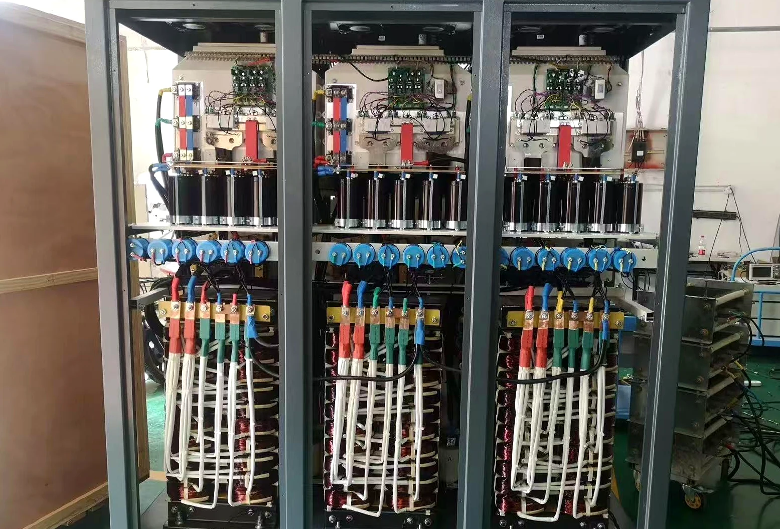
Open-frame partial discharge-free test power source in SDACME workshop
SDACME Test Power Source

Configuration Starts from the Test Requirement

The power-source configuration can vary according to the required transformer test voltage, frequency, capacity, input conditions and the surrounding PD / IVPD test arrangement.

Information for Technical Review

Define These Conditions Before Selecting the Source

01
Transformer / DUT Data

Transformer type, rated power, rated voltages and relevant nameplate information.

02
所需测试 V电压

Define the excitation or test voltage required by the selected transformer test arrangement.

03
测试频率

Required operating frequency or frequency range according to the applicable test method.

04
Required kVA / Current

Provide the required source capacity or excitation current when already known from the test design.

05
Voltage Transformation

Identify the existing excitation or step-up transformer and its required relationship to the power source.

06
Compensation Arrangement

Confirm whether reactors or other compensation equipment form part of the planned test circuit.

07
PD Measurement Setup

Describe the existing PD detector and measuring chain so the excitation and measurement boundaries remain clear.

08
Available Site Input

Provide the available incoming voltage, frequency and relevant installation conditions.

Source kVA is not the only selection parameter.

Voltage, frequency, transformer characteristics and the complete excitation arrangement can affect the required source configuration. Final selection should therefore be based on the actual transformer test condition.

Do not know the required test-source kVA yet?

Send the transformer nameplate, required test voltage and frequency, plus information about the existing excitation and PD measurement arrangement. SDACME can review the required power-source configuration.

发送测试要求
系统边界

Test Power Source vs. Partial Discharge Measurement System

These two parts of a transformer PD test solve different engineering problems. Separating the excitation function from the measurement function helps define the correct equipment and RFQ scope.

Excitation Function

变压器测试电源

✓
Creates the electrical test condition

Supplies the required AC excitation to the test arrangement.

✓
Controls output frequency

Supports the frequency required by the selected transformer test method.

✓
Provides required source capacity

Configured according to the DUT and test arrangement.

Measurement Function

PD Measuring Chain

✓
Couples the discharge signal

Transfers relevant PD signal information from the test circuit.

✓
Detects and displays PD activity

Performed by dedicated partial-discharge measuring equipment.

✓
Supports measurement evaluation

Results are interpreted according to the applicable test criteria.

SDACME's page focus is the excitation power source.

Other equipment such as coupling devices, PD detectors, voltage transformation and compensation equipment may form part of the wider transformer test arrangement and should be defined according to the specific project scope.

Test Power Source Capability

SDACME Power-Source Capabilities for Transformer PD Testing

SDACME supplies configurable variable-frequency AC test power sources for transformer partial discharge and induced-voltage test applications. The final source configuration is selected according to the required voltage, frequency, capacity, installation condition and the wider transformer test arrangement.

Available Capacity Range 5–2000 kVA
输出频率 45–200 Hz
Output Voltage Reference 0–1000 L V -L
Output Arrangement Transformer-Isolated Output
波形 Pure Sine-Wave Output
Configuration Basis Project-Selected
Selection note

These are product-family reference capabilities. Final input, output and test-source configuration should be confirmed against the actual transformer PD / IVPD test requirement.
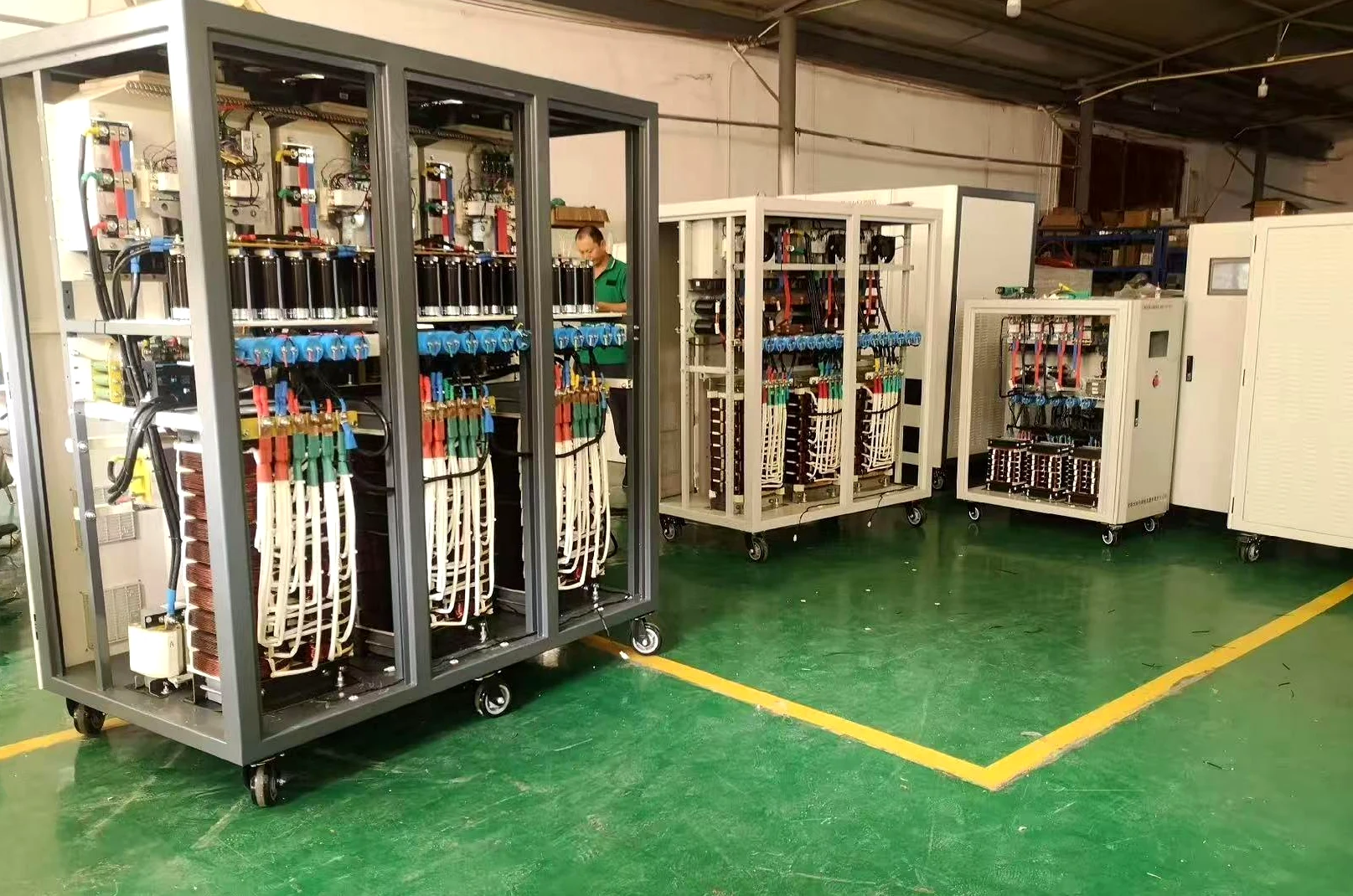
Manufacturing Evidence
SDACME Factory View
Multiple partial discharge-free test power source units in SDACME factory

Multiple Configurations Built for Test Applications

The variable-frequency test power-source platform can be configured for different transformer electrical test requirements, helping laboratories and manufacturers match the source to the intended PD / IVPD application.

SDACME Manufacturing

Configured and Built for Transformer Test Requirements

Transformer PD test projects can require different source capacity, voltage, frequency and installation conditions. SDACME reviews the application requirements before the test power source configuration is finalized for production.

1
Requirement Review

Transformer data, test voltage, frequency, capacity and available site power are reviewed as configuration inputs.

2
Configuration & Assembly

The power-source configuration is manufactured and assembled according to the agreed project requirements.

3
Pre-Shipment Verification

Applicable functional and output checks can be completed under the agreed pre-shipment verification scope.
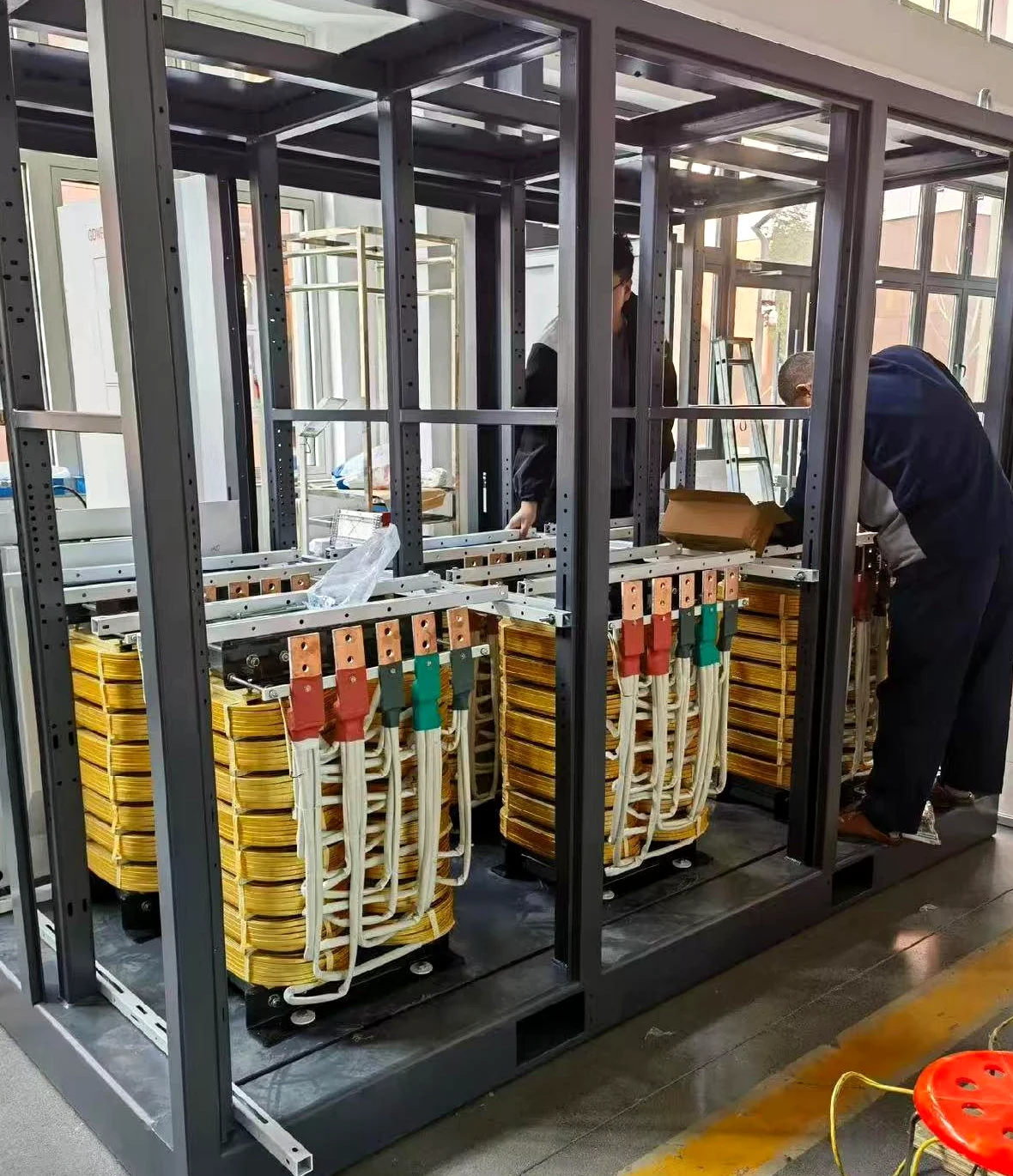

Partial discharge test power source assembly in progress at SDACME factory
Test power source assembly in progress at the SDACME factory.
FAQ / GEO Direct Answers

Transformer Partial Discharge Test FAQs

Common engineering questions about transformer PD testing, IVPD excitation and the role of the test power source.

What is a transformer partial discharge test?

A transformer partial discharge test evaluates localized electrical discharge activity in the insulation system while the transformer is subjected to a defined electrical test condition. The exact test connection, voltage sequence and acceptance criteria depend on the applicable test procedure.

What does the power source do during a transformer PD test?

The test power source establishes the electrical excitation required by the transformer test, including the selected voltage, frequency and source capacity. It provides excitation rather than performing the PD measurement itself.

Is a PD test power supply the same as a PD detector?

No. The power source energizes the test arrangement. A dedicated PD measuring chain detects and evaluates partial-discharge signals. Both functions may be required in the complete test setup, but they are different pieces of equipment.

Why is variable-frequency power used for transformer PD testing?

The required excitation frequency can depend on the transformer test method and test-system configuration. A variable-frequency source allows the required test frequency to be set independently of the incoming utility frequency.

What is an IVPD test?

IVPD refers to an induced-voltage test arrangement in which partial-discharge measurement forms part of the test evaluation. The excitation source and the PD measurement system continue to perform separate functions within the overall arrangement.

How is a transformer PD test power source selected?

Selection should consider the transformer data, required test voltage, frequency, source capacity or current, voltage transformation, compensation arrangement, available input power and the existing PD measurement setup.

Can a standard industrial frequency converter be used for PD testing?

Frequency conversion alone is not the only consideration. Transformer PD testing also requires attention to the source output quality, electrical background, isolation arrangement and compatibility with the complete test setup. The source should therefore be evaluated against the actual PD test requirements.

What information should I send for power-source configuration?

Send the transformer nameplate or rated data, required test voltage, test frequency, required capacity or current if known, existing excitation or step-up transformer, compensation equipment, PD measurement system, available input supply and project destination.

Power source selection starts with the transformer test condition.

If the required source kVA is not yet known, send the transformer data and test requirement so the excitation-power configuration can be reviewed.

Transformer PD Test RFQ

Configure the Power Source for Your Transformer PD Test

Send the transformer data and required PD / IVPD test condition. SDACME can review the required variable-frequency excitation source and prepare a project-specific power-supply configuration.

Useful Information for Configuration

Transformer Data Type, rated power and rated voltages
Test Voltage Required excitation / test voltage
测试频率 Required Hz or frequency range
Source Capacity Required kVA / current if known
现有设备 Excitation transformer / compensation
PD测量 Existing detector and measuring arrangement
Site Input Power Available voltage and frequency
项目信息 Quantity, destination and schedule
If some electrical parameters are not yet available, send the transformer nameplate and your planned test requirement first.