
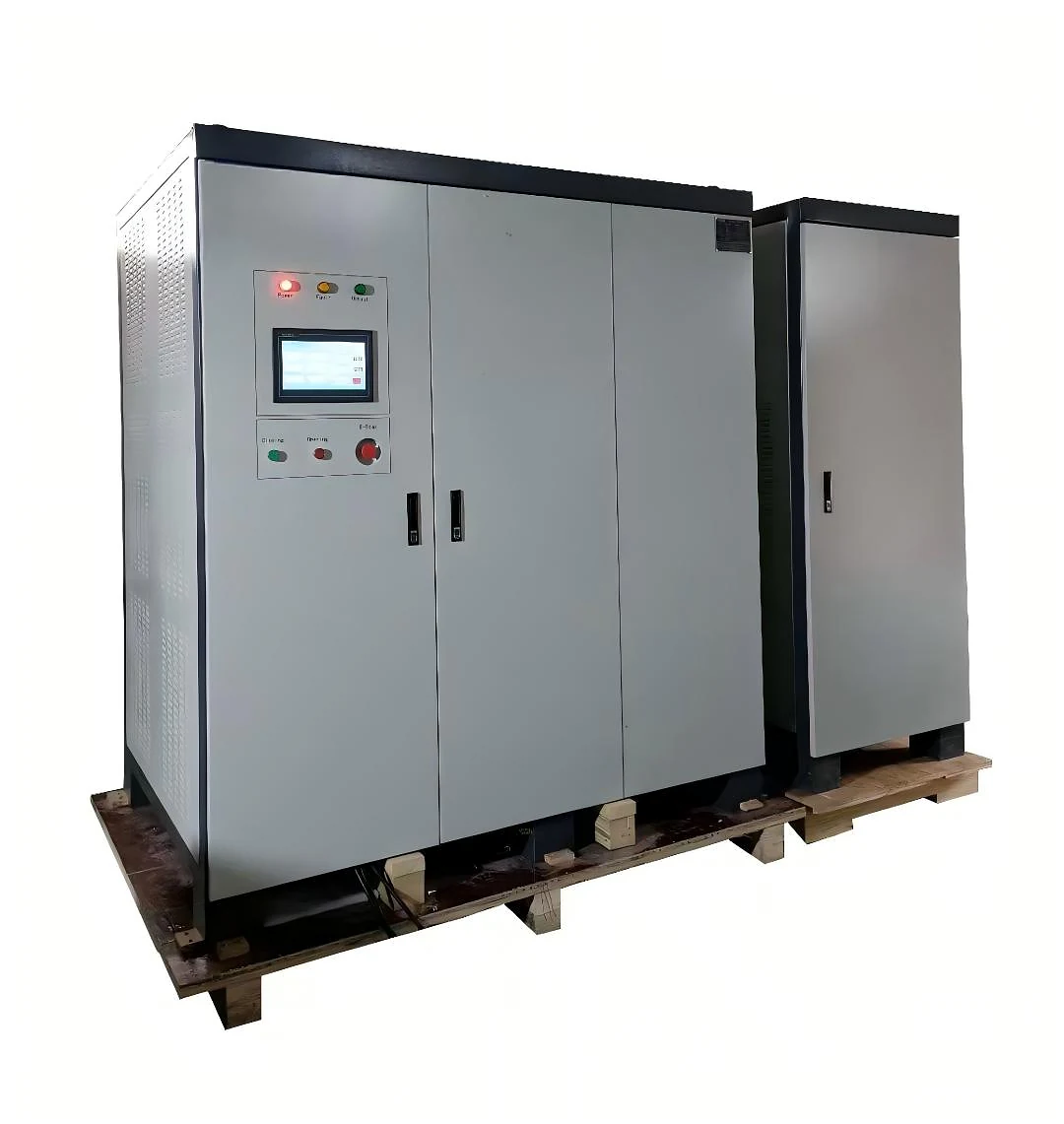
V变频测试功率用于变压器应用
SDACME 的部分放电无故障电源是为变压器测试而设计的交流测试电源,需要具备可调电压、频率、波形质量以及可控测试条件。.
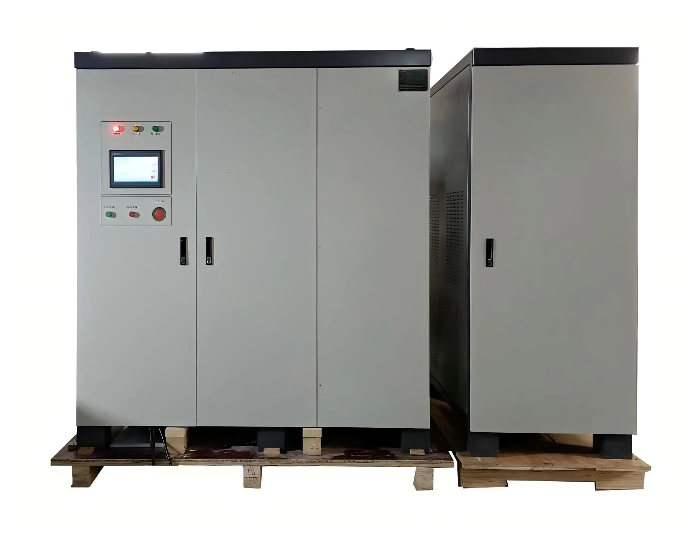
测试电源 — 不是 PD 测量仪器
变频器为变压器测试电路提供受控交流励磁。完整的测试系统中使用的相应测量设备用于检测和测量部分放电情况。.
可调节的交流电压和频率,满足适用于变压器测试的要求。.
测量、传感和其他测试系统组件将根据所需的测试方案进行配置。.
- 部分放电测试
- 诱发抗 V压电压测试
- 无负荷损耗测试
- 负载测试
- 温度升高测试
部分放电和诱 V发电压应用的测试功率
SDACME部分放电无故障电源为变压器测试装置提供可控变频交流电源,适用于需要稳定励磁、可调频率和电气隔离的测试环境。.
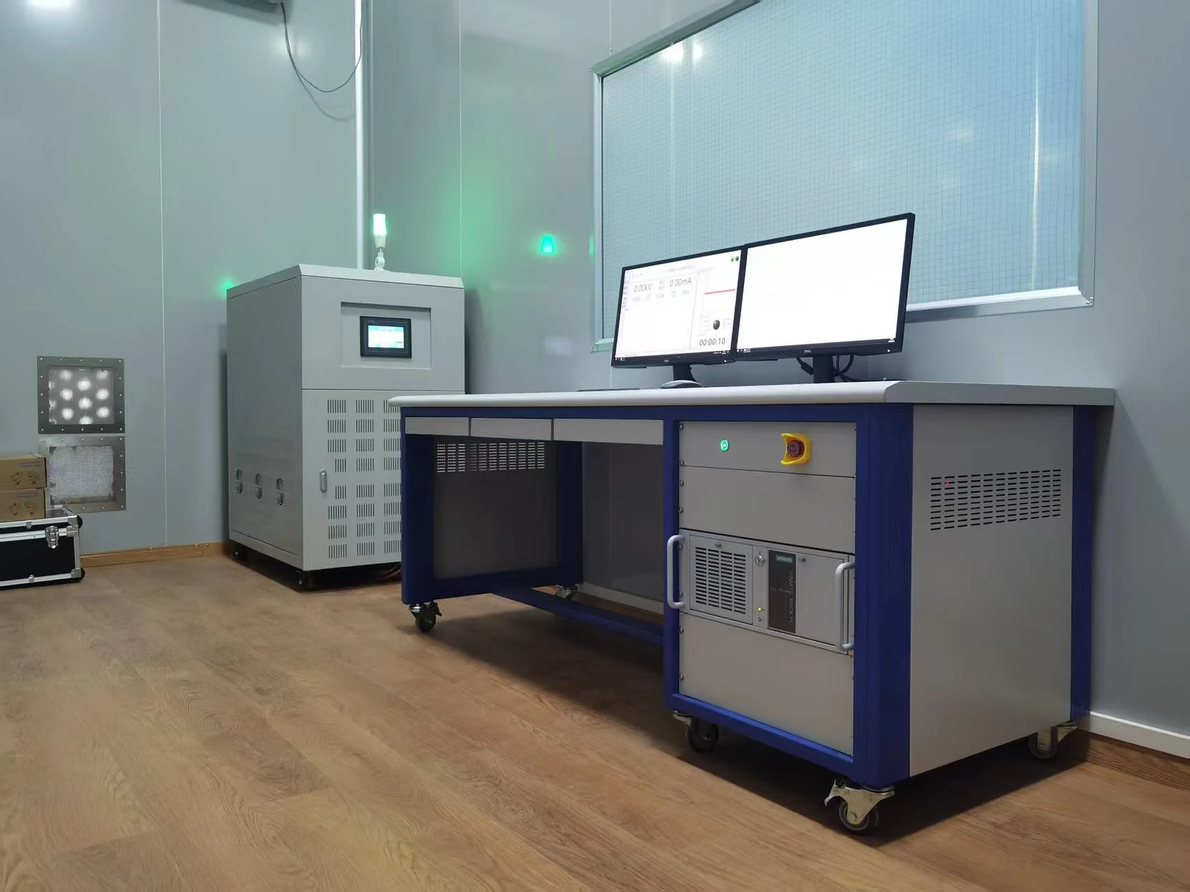 主要应用
主要应用 部分放电测试
该电源为变压器部分放电测试装置提供可调节的交流励磁电源,作为与所需测量设备一起使用的控制测试电源。.
- V可变频率交流激励
- 变压器隔离输出
- 控制电压和频率
- 专为变压器测试电源应用而设计
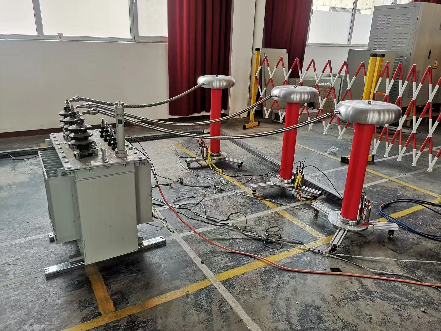 主要应用
主要应用 诱发抗 V压电压测试
可调频输出支持变压器诱发电压和诱电阻抗测试的要求,其中激励频率和测试电压必须与选定的测试方案相匹配。.
- 可调节的测试频率
- 控制交流测试电压
- 正弦波输出
- 基于测试需求的项目配置
其他变压器测试应用
当所需电气条件与配置的电源能力相匹配时,同一电源也可以支持选定的变压器测试任务。.
为适用于变压器的无负荷测试方案提供交流测试电源。.
可以为选定的变压器负载测试配置提供所需的测试电源。.
支持选定的配置所要求的适用于变压器温度升降测试功率要求。.
测试测量、传感、变压器连接以及其他测试系统组件的选型应根据所需的测试方法和项目配置进行。.
在敏感变压器测试条件下采用控制式交流电源
变压器部分放电和诱发电压测试对励磁电源提出了特殊的要求。输出波形、电压稳定性、频率稳定性、电气隔离以及输出调节等都对控制变压器测试环境起着重要作用。.
测试电源的用途不仅仅是改变频率。它必须提供适合所选变压器测试配置的恒流输出。.
正弦波输出支持变压器测试励磁,其中波形质量是测试功率要求的重要部分。.
变压器隔离输出功能是测试电源架构的一部分,它将配置好的测试输出与输入电源分离。.
功率转换和输出调节阶段的设计目的是为适用变压器测试要求提供受控交流电源。.
控制的电压和频率有助于在选定的测试过程中保持所需的激励条件。.

主要输出特性
电源提供激励源。最终测量性能还取决于所测试的变压器、测量设备、测试连接、接地以及整个测试设置。.
根据变压器测试要求配置电源
应根据实际变压器测试任务、所需电气条件和现有设施供应情况选择合适的部分放电无故障供电装置。仅靠容量本身不足以确定最终的设备配置。.
该系列产品的功能范围为设备选择提供了起点。最终配置将根据预期测试应用和所需的输出条件进行评审。.
报价前应该确认哪些事项?
提供以下项目信息有助于 SDACME 评估所需电源配置,以便编制报价单。.
在选择所需的测试电源之前,必须确定需要进行什么样的变压器测试。.
审查可用的输入功率以及所需的电压、频率、相位和输出条件。.
在审查实际变压器和测试要求后,将确定选定的设备配置。.
仅靠变压器的额定容量并不能确定所需的供电额定值。在最终选择设备之前,应首先结合测试类型、测试电压、频率、变压器特性以及完整的测试方案进行综合评估。.
提供可用的项目信息,SDACME将对合适的部分放电无故障供电配置进行评估,以便提供报价。.
本地 HMI 监控与集成式电气保护
这种无部分放电电源能够提供关键电气参数的局部运行可视性,同时具备集成式保护功能,用于控制变压器测试电源的运行。.
操作员界面上的关键电气参数
本地接口为操作员提供了在运行期间监测配置测试功率输出所需的主要电气信息。.
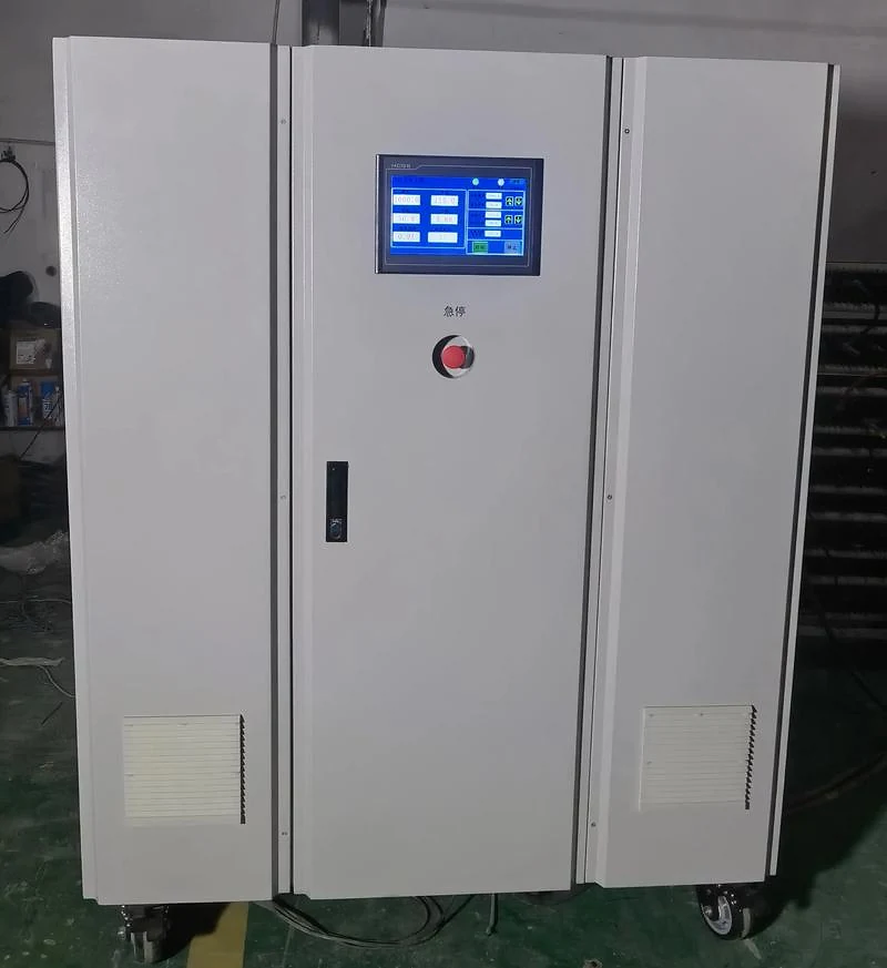
The reference configuration uses a color touchscreen for local operation and parameter monitoring. Final interface details follow the selected equipment configuration.
Electrical Protection Functions
Protection functions are integrated into the equipment to support controlled operation under abnormal electrical or thermal conditions.
The operator interface provides local access to the principal operating functions of the configured system.
Operating information and system status are presented to support equipment monitoring during the transformer test process.
The reference technical configuration includes power-failure output and indication functions as part of equipment operation.
Public product information describes the available monitoring and protection functions. Detailed protection settings, control logic and project-specific operating parameters are defined for the selected equipment configuration.
Manufactured and Factory-Tested for Transformer Test Power Applications
SDACME manufactures partial discharge-free frequency converter systems for transformer test power applications, from cabinet assembly and equipment integration through factory verification and preparation for delivery.
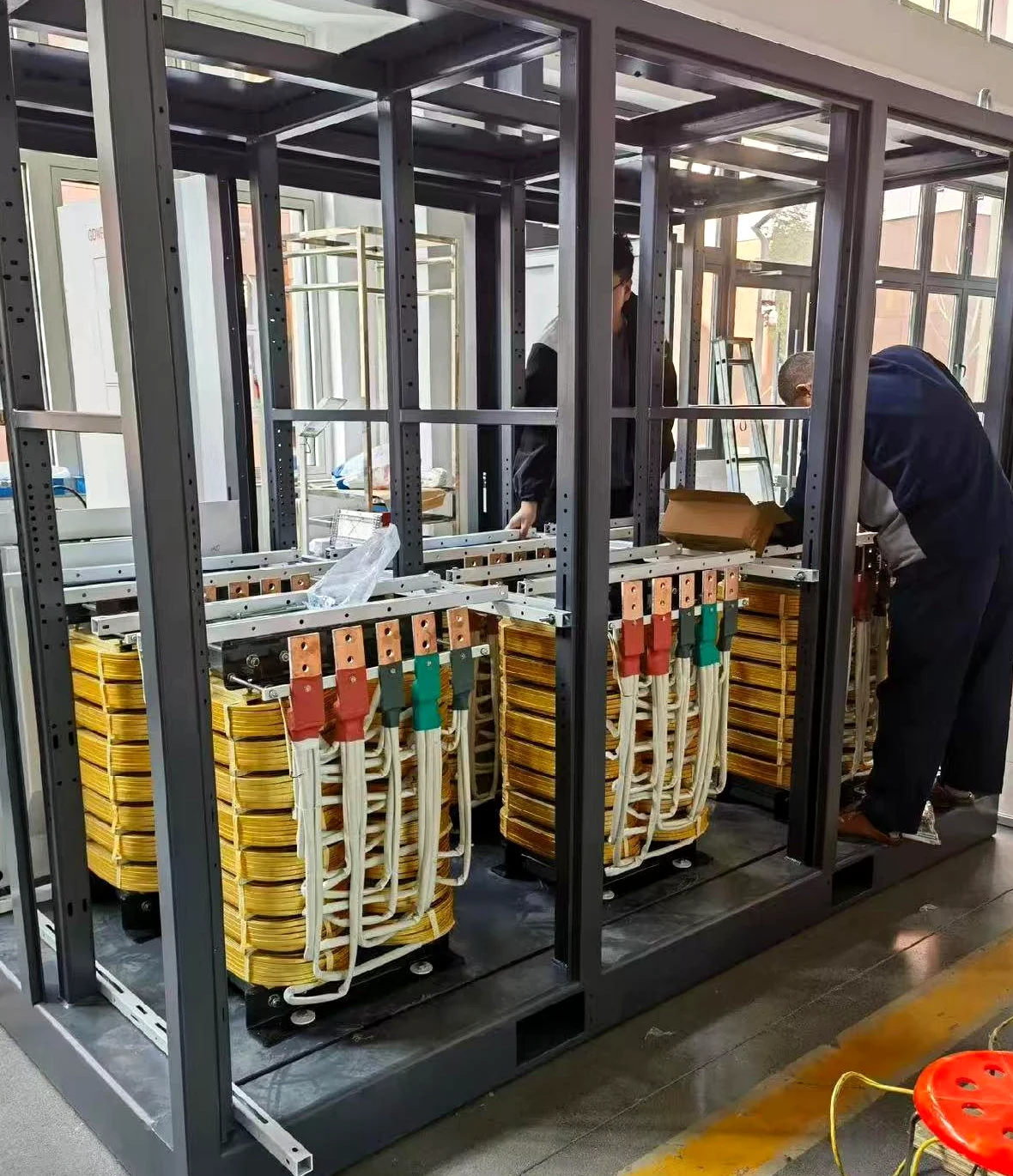
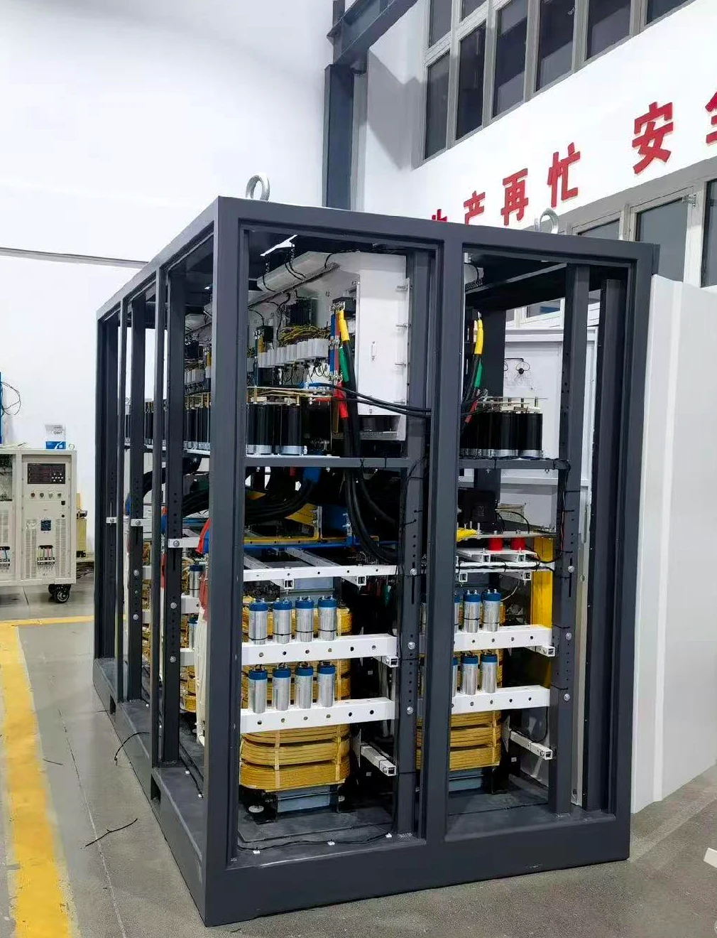
Actual workshop equipment showing cabinet assembly and manufacturing work in progress.
From Equipment Assembly to Factory Verification
Each project begins with the required transformer test duty and electrical configuration. The equipment is then prepared around the selected capacity, test conditions and project interfaces.
- Power conversion cabinet assembly
- Configured equipment integration
- Local control and monitoring interface
- Factory equipment verification
- Preparation for project delivery
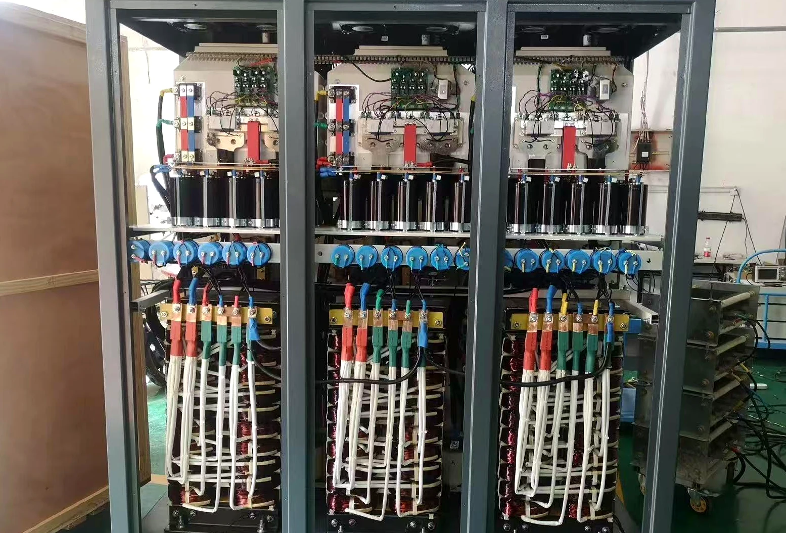
Workshop view showing an actual equipment configuration during the manufacturing stage.
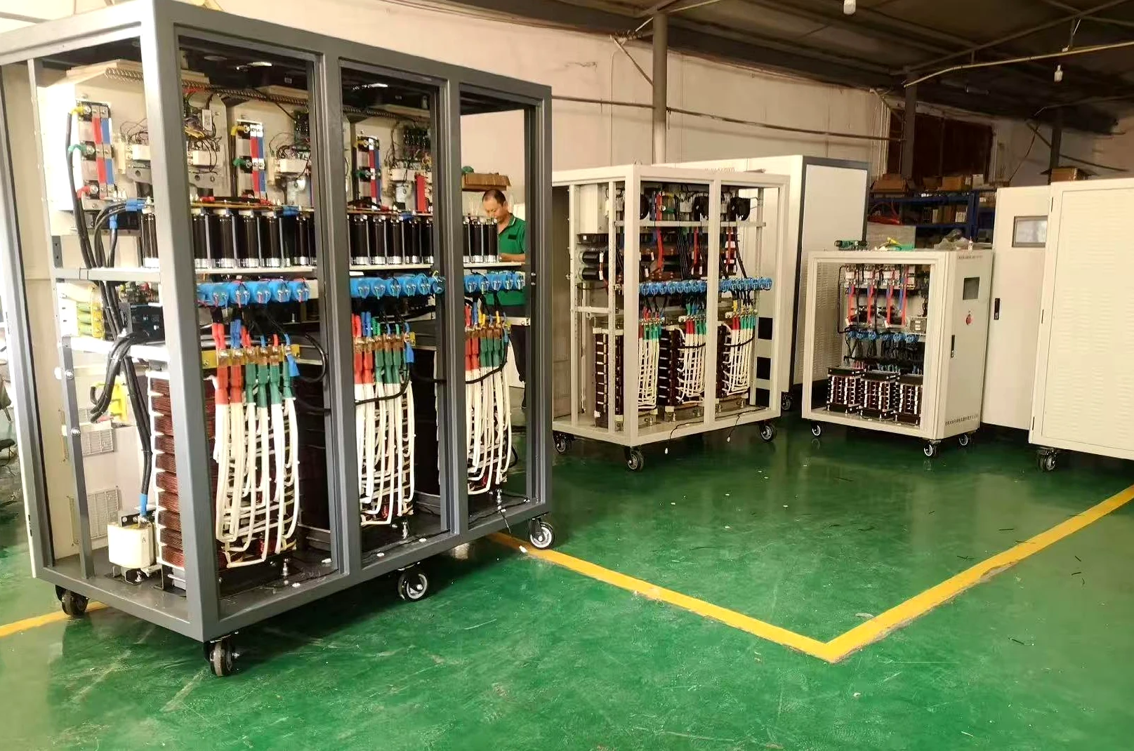
Actual factory equipment demonstrates manufacturing activity across different cabinet configurations.
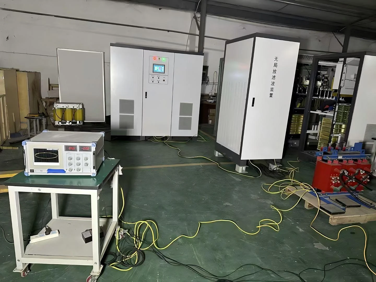
Factory testing provides verification of the configured equipment before shipment and project use.
From Requirement Review to Factory Test
The manufacturing process follows the selected transformer test requirement and equipment configuration through assembly, integration and factory verification.
Transformer information, test duty and required electrical conditions are reviewed before equipment configuration.
Power supply cabinets are assembled according to the selected project configuration.
Control, monitoring and the required equipment functions are integrated into the configured system.
The completed equipment is checked and tested before preparation for delivery.
Factory test documentation is included with the referenced partial discharge-free frequency converter equipment package.
From Test Environment to Equipment Delivery
Real equipment, transformer test environments and delivery preparation provide practical evidence behind the SDACME partial discharge-free power supply product line.
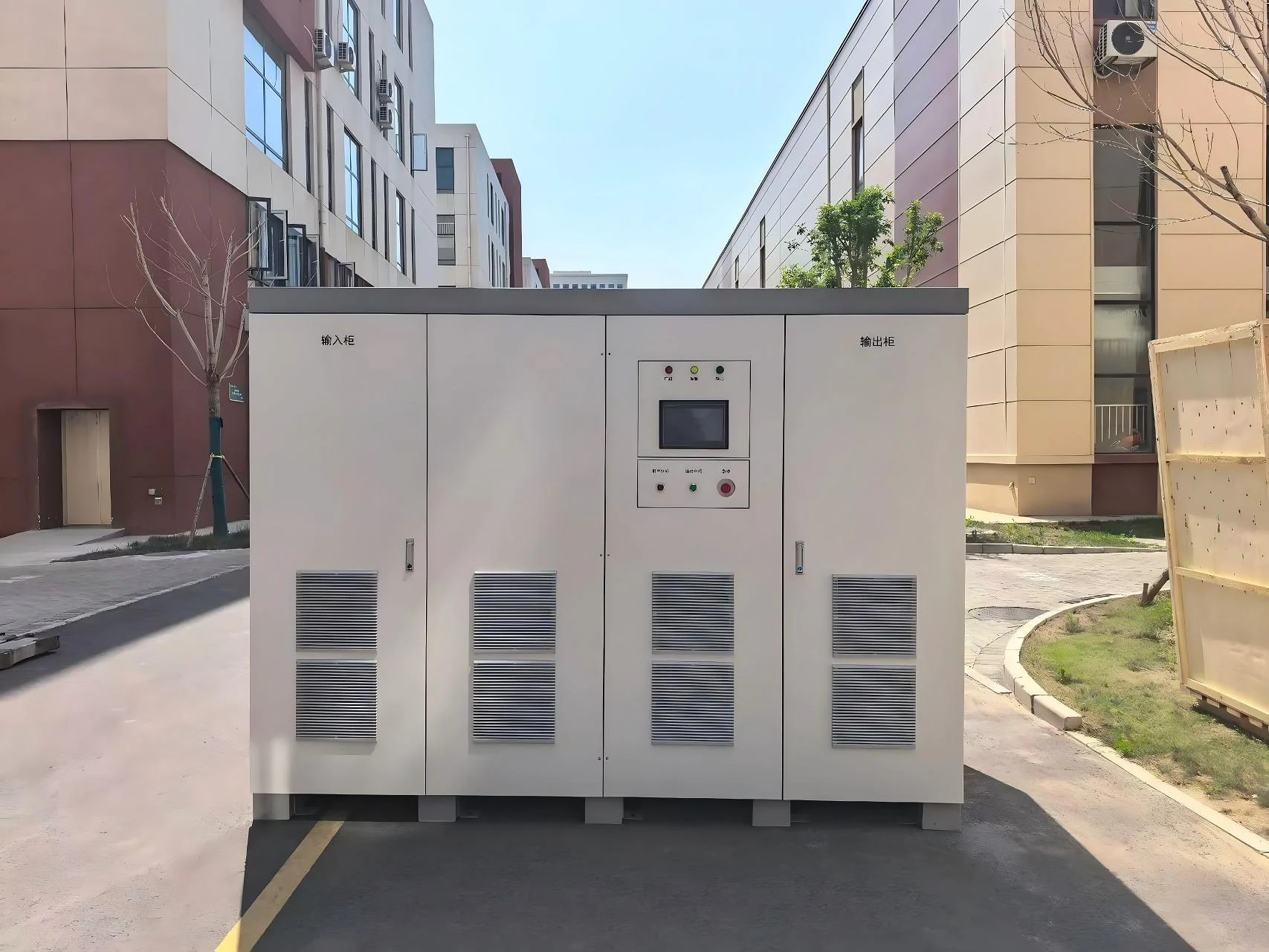
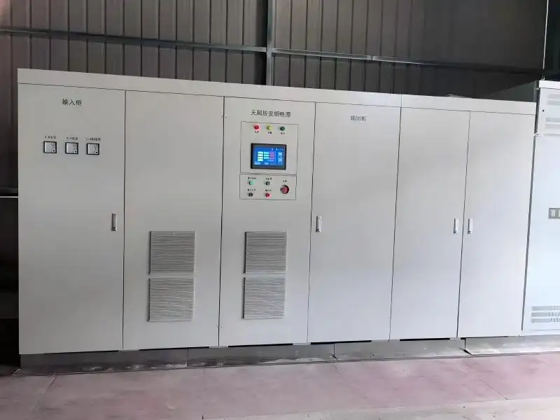
设备安装
Actual partial discharge-free power supply equipment shown in an installation environment.
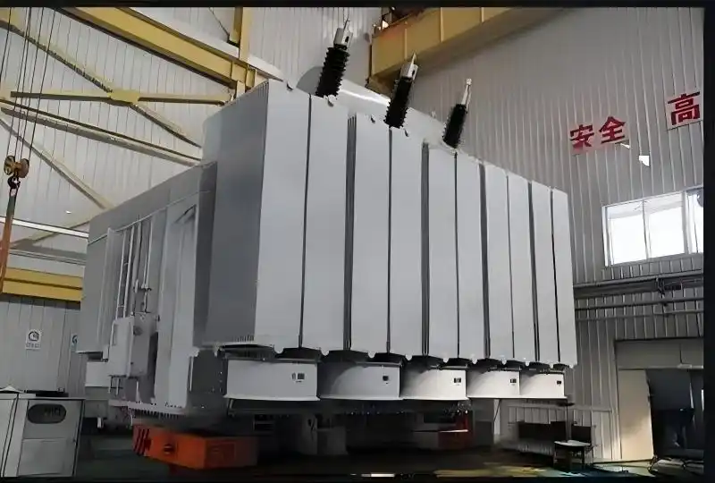
High-Voltage Transformer Test Setup
Real transformer-related test environment showing the type of application in which controlled test power equipment is used.
2000 kVA 参考设备
Actual large-capacity equipment providing a physical reference within the stated 5–2000 kVA product range.
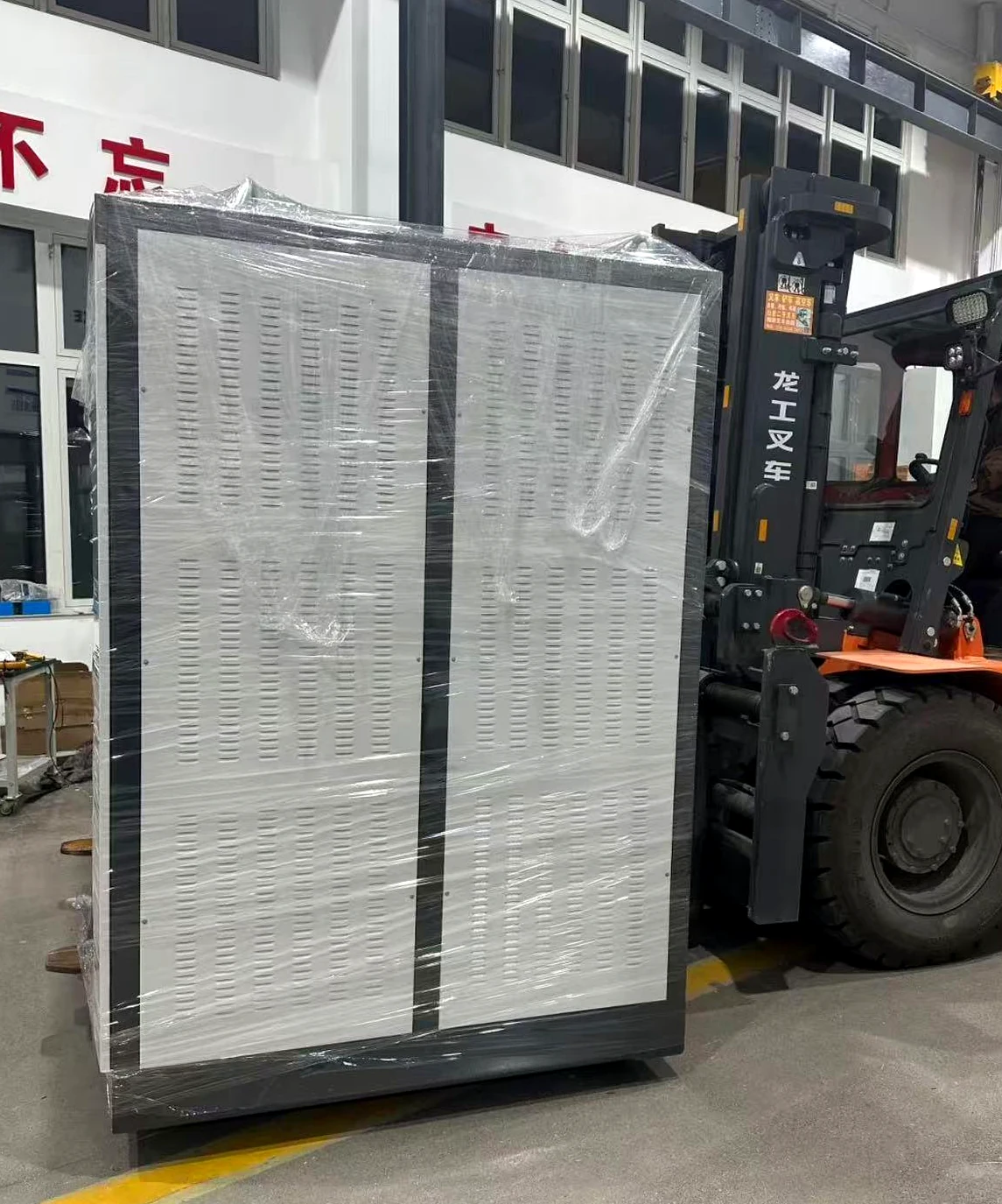
Equipment Prepared for Shipment
Finished power supply equipment packed and prepared for project delivery.
What These Images Demonstrate
The product is represented by actual manufactured systems rather than conceptual product renderings.
Test-area evidence supports the product positioning as a power source for transformer test applications.
Combined with the factory evidence above, the page documents the path from manufacturing through testing and shipment preparation.
The equipment shown represents real manufactured and test-related examples. Final capacity, electrical interfaces and test conditions are defined according to the selected project configuration.
