Shore Power System Engineering

岸上电力系统架构与组件

A complete shore power system is more than a frequency converter. It coordinates grid connection, voltage transformation, frequency conversion, switchgear, protection, control, cable management and the vessel interface as one integrated electrical system.

LV & HV Architectures 50 Hz / 60 Hz Conversion Transformer & Switchgear Integration 保护与控制 Shore Connection & Cable Management
系统架构
Shore Grid to Vessel Power Chain
项目特定
01
Port / Utility Grid
Incoming electrical supply
02
Switchgear
Switching, metering & protection
03
变压器
Where Required
04
频率转换
If Frequency Conversion Is Required
05
输出保护
Switchgear, protection & grounding
06
海岸连接
Connection box & cable interface
07
Cable Management
Depending on Berth Interface
08
VEssel 界面
Receiving system / main switchboard
09
Vessel Loads
Hotel and operational electrical loads
Control & Monitoring Layer
PLC
HMI
计量
报警器
SCADA
交流
A
Architecture Principle
No single fixed equipment chain fits every shore power project.
V
Electrical Matching
Shore voltage and frequency must match vessel requirements.
P
Project Engineering
Final configuration depends on grid, vessel, berth and operating conditions.
Architecture Fundamentals

There Is No Single Fixed Shore Power Architecture

A shore power system should be engineered around the electrical conditions of both the shore and the vessel. Equipment arrangement, voltage transformation, frequency conversion, protection, connection and control requirements can therefore differ substantially between projects.

01

Shore-Side Conditions

  • Grid voltage
  • Grid frequency
  • Available power capacity
  • Earthing arrangement
  • Short-circuit level
  • Existing distribution system
02

Vessel-Side Conditions

  • 所需连接电压
  • 所需频率
  • Continuous operating load
  • Peak demand
  • 最大起重能力
  • Vessel connection interface
03

Project Conditions

  • Number of berths
  • Simultaneous vessel operation
  • Cable route and distance
  • Indoor or outdoor installation
  • Environmental conditions
  • 所需供应范围
Shore power system architecture should be defined from actual project electrical data rather than from a fixed equipment list.
End-to-End Power Chain

From the Port Grid to the Vessel

A complete shore power architecture coordinates power conversion, transformation, protection, control and the physical shore-to-vessel interface. The exact sequence depends on the project.

01

Port / Utility Grid

Incoming electrical supply and available port distribution capacity.

02

Incoming Switchgear

Switching, isolation, protection and electrical metering.

03

Input Transformer

Voltage adaptation or phase-shifting where required.

Where Required
04

频率转换器

Matches grid frequency to vessel frequency where conversion is required.

Conditional
05

Output Transformer

Voltage matching, isolation or grounding-related system functions.

Where Required
06

输出开关设备

Feeder protection, isolation, distribution and grounding coordination.

07

Connection & Cable Interface

Connection box, cables and cable-management arrangement.

08

Vessel Receiving System

Ship-side receiving equipment and vessel main electrical distribution.

Control & Monitoring Layer

PLC
HMI
计量
报警器
SCADA
交流

Not every shore power project requires every component shown above. Final equipment selection is based on grid conditions, vessel electrical requirements and the approved project architecture.

功率转换

How Conversion and Transformation Fit Into the Power Chain

Frequency and voltage are separate design requirements. Depending on the shore grid and vessel electrical system, a project may require frequency conversion, voltage transformation, both functions or neither.
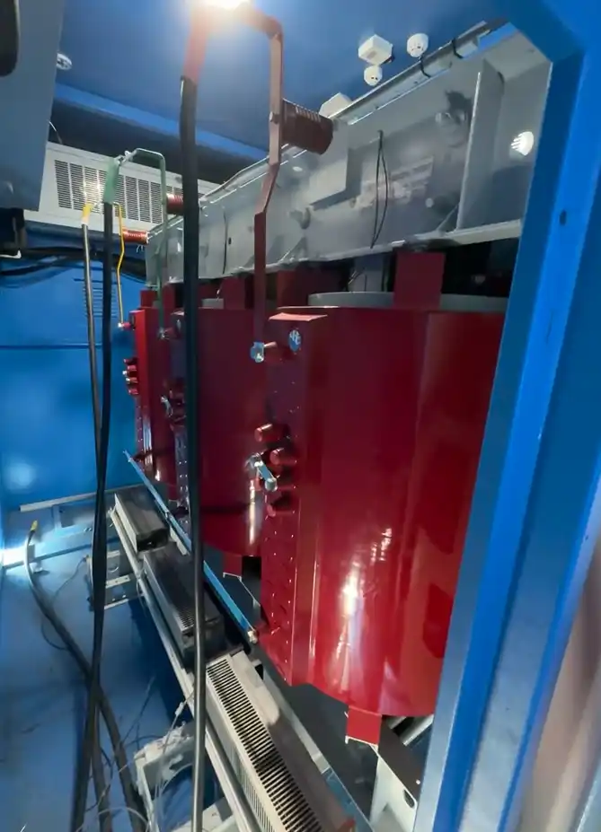
Shore power transformer for voltage conversion and system integration

岸上电力频率转换v器

Matches the shore supply frequency to the vessel requirement where the two systems operate at different frequencies, such as 50 Hz to 60 Hz or 60 Hz to 50 Hz.

Input / Phase-Shifting Transformer

May support incoming voltage adaptation, converter input requirements, isolation or phase-shifting functions associated with the selected conversion topology.

Isolation / Voltage-Matching Transformer

May provide step-up or step-down transformation, electrical isolation and support for the required grounding arrangement.
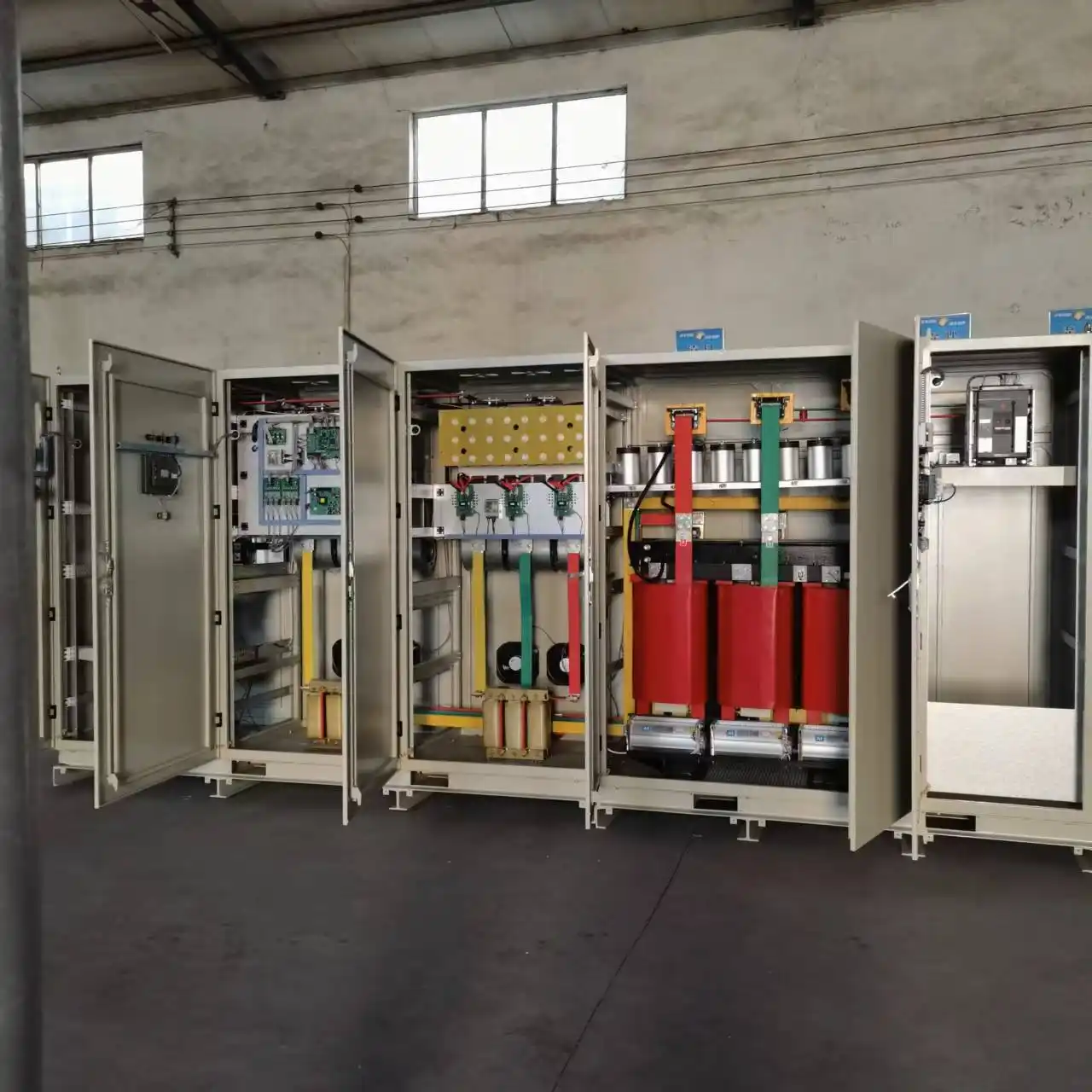
岸上电源变频器的内部组件
Conversion equipment is one subsystem within the complete architecture.

The final transformer and converter arrangement depends on grid voltage, vessel voltage, frequency requirements, grounding and the approved project configuration.

Protection Architecture

Switching, Protection and Grounding Must Work as One System

Shore power switchgear provides more than electrical switching. It forms part of a coordinated architecture involving isolation, protection, metering, feeder control, grounding and the vessel electrical system.

Incoming switchgear can provide isolation, switching, metering and feeder protection. Output switchgear can provide vessel feeder control, distribution, protection and coordination with connection interlocks.

Depending on the approved electrical design, protection may include:

  • 过电流保护
  • Overvoltage and undervoltage protection
  • Frequency and phase-related protection
  • Differential protection where required
  • Interlocking and emergency shutdown functions

Grounding and neutral-grounding equipment must be coordinated with transformer configuration, the vessel system, fault-current limits and the overall protection philosophy.

Switching

Isolation, feeder control and operating sequence.

保护

Coordinated fault detection and protective functions.

接地

Earthing and neutral treatment based on system design.
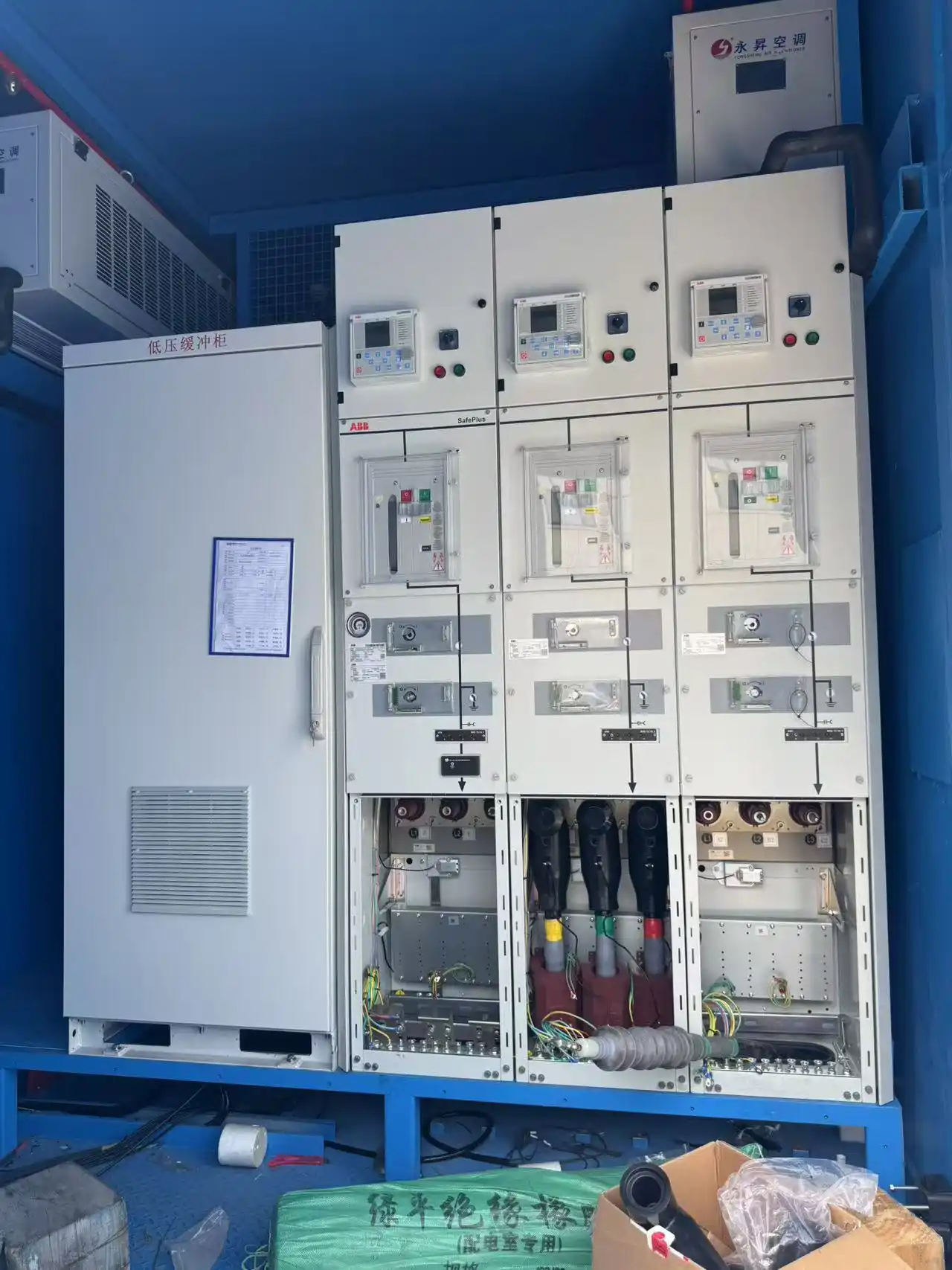
Shore power switchgear integration for protection and distribution
Control Architecture

The Power Layer and Control Layer Work Together

Main electrical equipment transfers power, while the control and information layer coordinates operating status, permissions, alarms, measurements and project-specific communication.

Power Layer
Grid
变压器
转换器
Switchgear
Connection
V埃塞尔
↕
Control & Information Layer
PLC
HMI
计量
报警器
SCADA
Ship–Shore Interface

本地控制

PLC and HMI coordinate system operation and provide local status information.

监控

Metering, alarms and event information support supervision and troubleshooting.

交流

SCADA and ship–shore interfaces can be configured according to project requirements.

SHORE CONNECTION BOX
动力
PE / EARTHING
控制
↓ Vessel Connection Interface
Berth-Side Interface

Shore Power Connection Box

A shore power connection box provides a defined electrical interface between the shore-side system and the cables connecting the vessel.

  • Main power connection
  • Earthing connection
  • Auxiliary or control connections
  • Status or interlock interfaces where required
  • Interface with the selected cable-management arrangement

Its configuration depends on voltage class, current, vessel interface, berth layout and the required operating method.

Physical Ship–Shore Interface

Shore Power Cable Management

The electrical system does not end at the output switchgear. Power, control and earthing conductors still need to be transferred and supported safely between the berth and vessel.

Deploy
Manage cable movement between shore and vessel.
Support
Support cable weight and operating position.
路线
Manage the required connection path and distance.
Protect
Reduce unnecessary mechanical stress on cables.
SHORE ELECTRICAL SYSTEM
↓
CONNECTION POINT
↓
CABLE MANAGEMENT
↓
POWER / CONTROL / EARTHING
↓
VESSEL INTERFACE
Project Variations

How Shore Power Architecture Changes by Project

Architecture changes when the electrical and operating conditions change.

SCENARIO 01

Same Frequency

Grid → Transformer if required → Protection → Vessel

Frequency conversion may not be required when shore and vessel frequency already match.

SCENARIO 02

Different Frequency

50 Hz Grid → Frequency Converter → 60 Hz Vessel

A converter becomes part of the power chain where grid and vessel frequencies differ.

SCENARIO 03

Different Voltage

Grid → Voltage-Matching Transformer → Vessel

Voltage transformation may still be required even when frequency already matches.

SCENARIO 04

Low Voltage vs High Voltage

Voltage Class → Current → Cables → Switchgear → Protection → Interface

LV and HV shore connections create different requirements for current, protection, grounding and connection equipment.

SCENARIO 05

Single Berth vs Multi-Berth

Central / Distributed Supply → Multiple Feeders → Berth 1 / 2 / 3

Multi-berth systems require review of simultaneous demand, independent feeders, connection locations and future expansion.

Need to define the architecture for a real port or vessel?
Start with the shore grid, vessel voltage, frequency, load and berth arrangement.
Discuss Your System Architecture
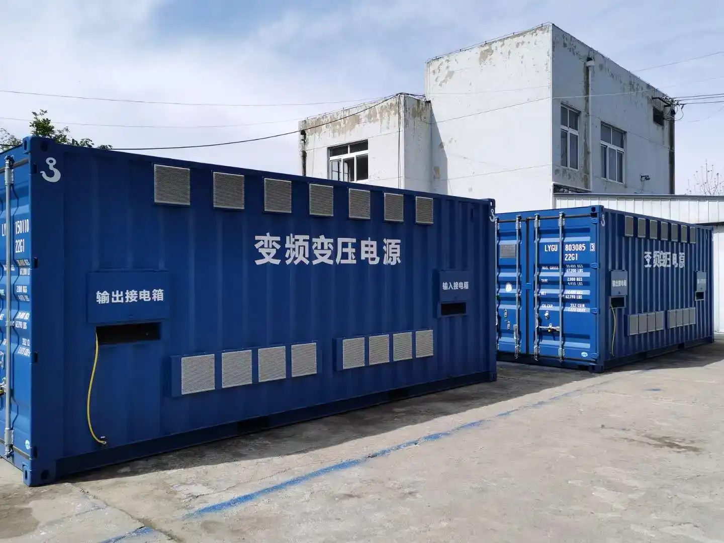
Containerized shore power equipment for marine installation environments
Integrated shore power equipment: physical arrangement and environmental protection are selected according to the installation conditions of each project.
Environmental Engineering

Site Conditions Can Change the Physical Architecture

Shore power equipment operates as part of a marine electrical installation. Temperature, humidity, salt, dust, altitude and maintenance access can affect cooling, insulation, enclosure requirements and equipment arrangement.

温度 Cooling capacity, thermal margin and equipment derating may need to be reviewed.
湿度 Condensation, insulation and environmental-control requirements should be considered.
Salt & Pollution Marine exposure can influence corrosion protection and insulation coordination.
Dust & Sand Local conditions can affect filtration and enclosure requirements.
海拔高度 Cooling and insulation performance may require additional engineering review.
Seismic / Vibration Mechanical installation requirements can be considered where specified by the project.
维护访问权限 Equipment arrangement should provide suitable space for inspection, servicing and component replacement.
Installation Location Indoor, outdoor and containerized arrangements can require different physical system designs.
Environmental design affects more than the enclosure. It can influence cooling, equipment arrangement, maintainability, insulation and the overall physical architecture of the shore power system.
Engineering FAQ

Shore Power System Architecture FAQs

Direct answers to common engineering questions about shore power system components and architecture.

What are the main components of a shore power system?
A complete system may include incoming switchgear, transformers, a shore power frequency converter, output switchgear, protection and grounding equipment, PLC/HMI control, a shore connection box, cables and cable-management equipment. The exact configuration depends on the shore grid and vessel requirements.
Is a frequency converter always required?
No. A frequency converter is normally required when the shore grid frequency and vessel frequency are different. If both already operate at the same frequency, frequency conversion may not be required.
When is a transformer required in a shore power system?
A transformer may be required for voltage matching, electrical isolation, converter input requirements or the selected grounding arrangement. Not every project requires the same transformer configuration.
What does shore power switchgear do?
Shore power switchgear provides switching, isolation, distribution and protection functions between the grid, conversion equipment and vessel connection.
What is a shore power connection box?
It is a berth-side electrical interface used to connect the shore system to vessel power, earthing and control cables.
What does a shore power cable management system do?
It supports the handling, routing and physical management of power and control cables between the berth and vessel.
How do PLC, HMI and SCADA work in a shore power system?
The PLC coordinates control functions, the HMI provides local operating information and commands, and a SCADA interface can support higher-level monitoring where required.
Why are grounding and protection part of the system architecture?
Fault current, transformer configuration, vessel earthing and protective-device operation are electrically related. Grounding and protection therefore need to be coordinated as one system.
Can one shore power system supply multiple berths?
Yes. Multi-berth installations can be designed, but the architecture depends on simultaneous load, feeder arrangement, berth locations, equipment sharing and redundancy requirements.
How do environmental conditions affect shore power architecture?
Temperature, humidity, salt, dust, altitude and installation location can affect cooling, corrosion protection, insulation, enclosure selection, derating and maintenance access.
项目配置

Send Your Shore Power System Requirements

The most effective way to define a shore power architecture is to begin with the actual shore grid, vessel electrical requirements, berth arrangement and required supply scope.

Request a Shore Power System Configuration →
Information for Preliminary Engineering
海岸网格 Voltage, frequency and available capacity
网格条件 Earthing and short-circuit level if available
Vessel Electrical Data 所需电压和频率
Load Information Continuous load, peak demand and largest motor
Berth Arrangement Number of berths and simultaneous vessel operation
Connection Cable distance and vessel interface if known
安装 Indoor, outdoor or containerized arrangement
环境 Temperature, humidity and marine conditions
供应范围 Converter, transformer, switchgear, control, connection or complete package
Project Documents SLD, load list, vessel specification or tender requirements
If available, send the vessel electrical specification, existing single-line diagram, load list or tender technical specification. These documents help define the required architecture more accurately.