Microwave Generator Control System for Monitoring, Protection & OEM Integration
Integrate industrial microwave power into OEM equipment with a control system designed around local operation, industrial communication, operating-status monitoring, alarms, interlocks and model-specific protection functions. SDACME reviews the required control boundary against the customer automation platform and machine-level safety requirements so the selected generator can be configured for the actual project.
Control Integration — Public Architecture View
*Interface scope and available functions depend on the selected generator and project configuration.
Control Architecture
Control, Monitoring and Protection Are Three Connected Layers
A microwave generator control system coordinates operator control, external automation, operating feedback and protective response. For OEM integration, SDACME reviews these functions as three connected layers: control, monitoring and protection.
控制
Local operation and the agreed external automation interface.
监控
Operating status and selected microwave or equipment information.
保护
Model-specific protection and machine-level interlock coordination.
Conceptual Integration Boundary
For new or existing equipment, the interface is reviewed against the customer automation and safety architecture before the generator configuration is finalized.
Review Control Architecture本地运营
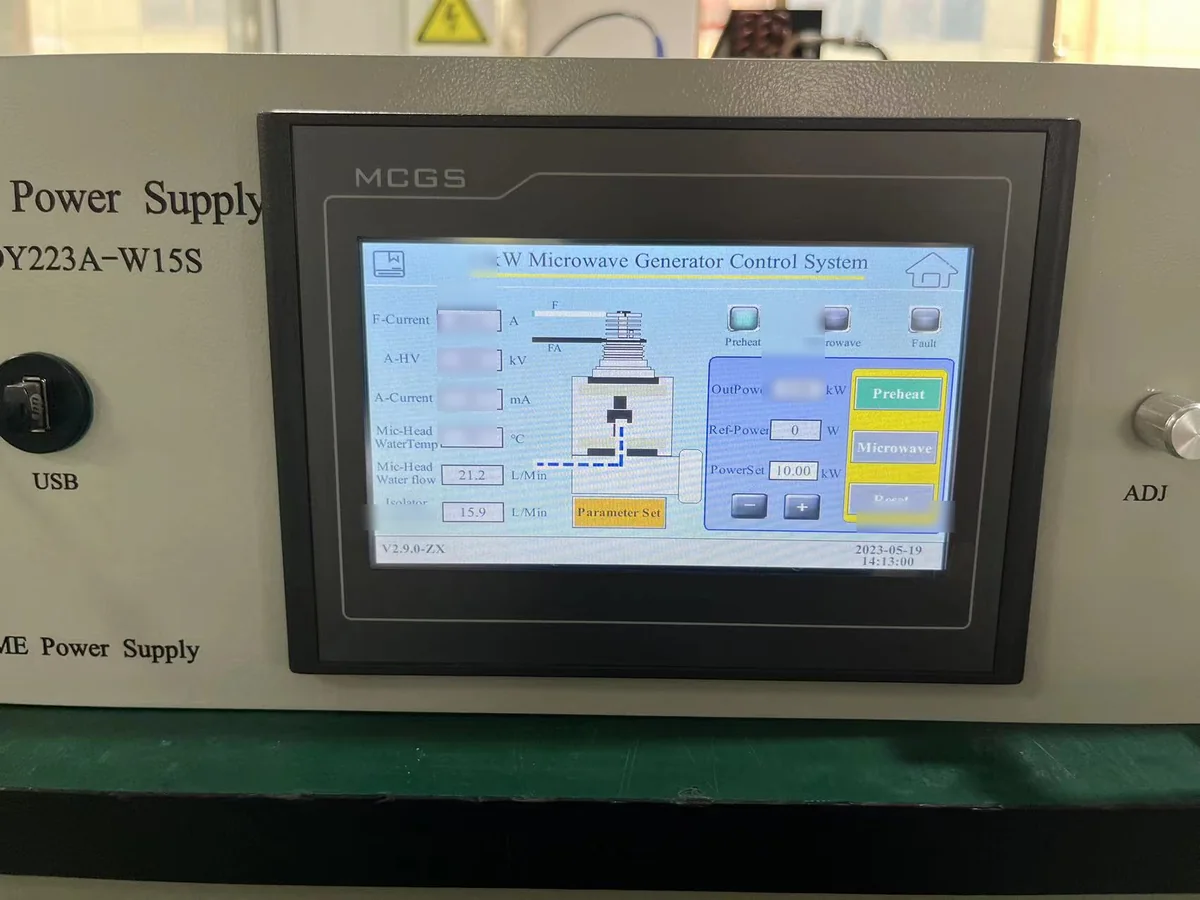
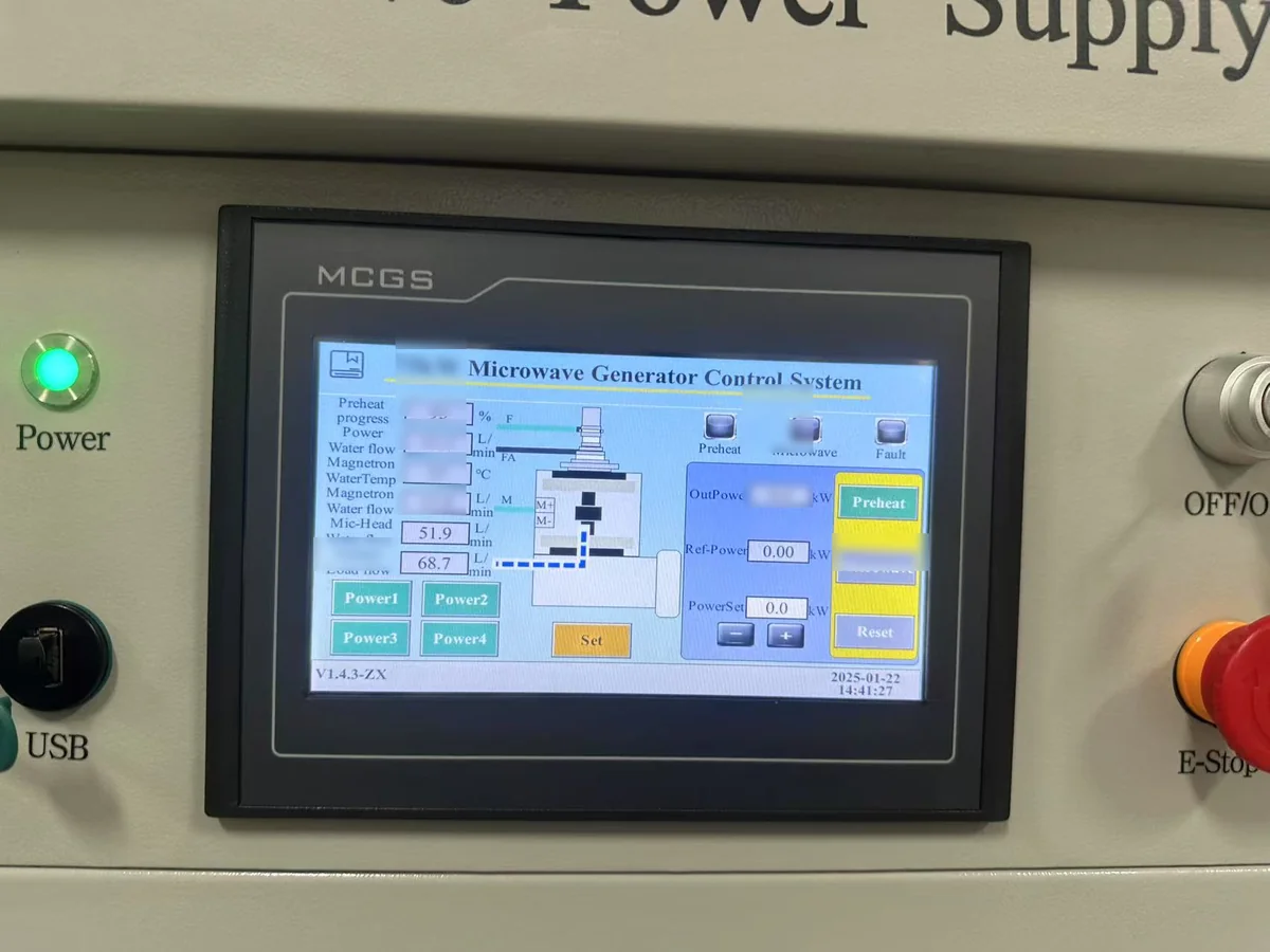
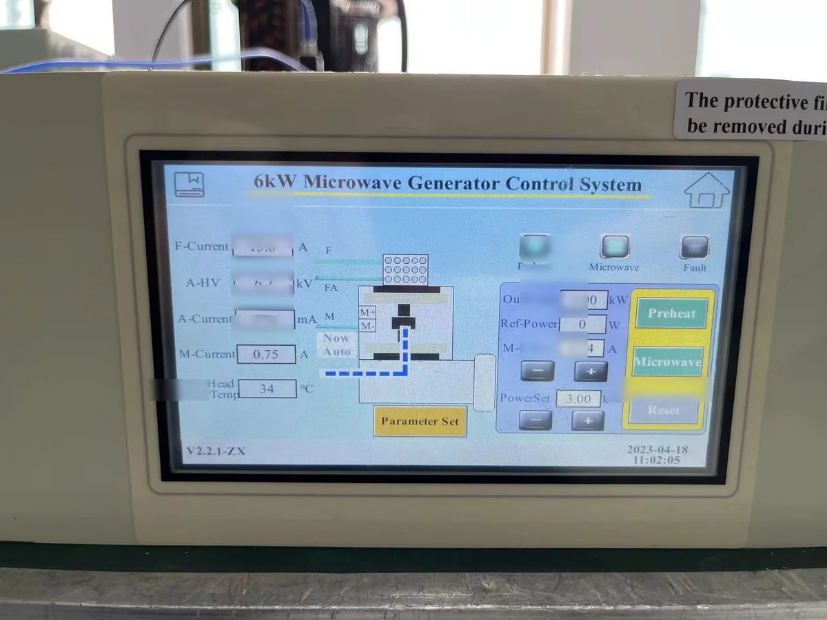
Local HMI for Commissioning, Operation and Fault Review
Applicable SDACME microwave generator configurations use a local HMI or touchscreen for essential operator functions. Depending on the selected model, the interface can support operation, microwave-power adjustment, status viewing and alarm/fault review.
Communication & OEM Integration
Define the PLC and Communication Requirement Before Integration
Industrial communication requirements should be selected from the customer automation architecture. RS485 is available on confirmed current SDACME microwave generator configurations, and Modbus RTU is supported on confirmed configurations. The final communication scope is confirmed for the selected generator and project.
RS485
Available on confirmed current configurations. Final communication scope is confirmed for the selected generator.
Modbus RTU
Available on confirmed configurations. Applicable interface documentation is project- and model-specific.
External PLC
External machine control can be integrated through the agreed automation interface and functional boundary.
Digital I/O
Digital or dry-contact interfaces can be evaluated where required. Final signal scope is defined for the project.
0–10 V / 4–20 mA and Other Industrial Interfaces
Analog interfaces and other plant-standard communication requirements can be evaluated for the selected control configuration. Compatibility is reviewed by project and is not presented as a universal product-line feature.
Detailed interface maps, register definitions, wiring and internal control implementation are handled within project engineering documentation where required.
Send PLC / Protocol RequirementsPower Control & Monitoring
Control the Required Power and Monitor the Operating State
The microwave generator can accept operating commands through the applicable local or remote control route, while available monitoring functions depend on the selected model and control package. Typical project requirements may include operating state, microwave-power information, selected electrical/cooling status and alarm information.

Representative HMI view. Displayed information and screen layout vary by model and control version.
Operating Control
Essential operating commands and control state through the applicable local or external-control route.
微波状态
Power-related and RF-condition information where configured for the selected generator.
Equipment Status
Selected electrical, thermal or cooling information depending on the installed monitoring package.
Alarms & Records
Alarm, fault and selected history functions where available on the applicable control version.
RF / Load Conditions
Monitor RF Load Conditions and Coordinate Protective Response
Changes in load or matching conditions can affect reflected microwave power. On applicable configurations, reflected-power information and other protection functions can be coordinated to help protect the microwave source and connected RF system.
RF Condition Monitoring
Applicable configurations can monitor RF or load conditions as part of the protection strategy.
Abnormal Load Response
Protective response is coordinated with the selected generator and RF system.
Arc / Load Protection
Capability is model- and configuration-dependent and is confirmed during engineering review.
System Coordination
RF components, matching and process equipment must be considered together with generator protection.
Protection performance depends on the generator, RF system, load condition and project configuration. Correct applicator design, matching, isolation and process control remain part of the overall system design.
Discuss Load & Reflection ConditionsProtection Categories
Coordinate Electrical and Cooling Protection with the Selected Generator
The generator control system can supervise several categories of abnormal operating conditions. Depending on the selected model, these can include electrical, thermal, cooling and microwave-side protection functions.
电气
Abnormal electrical operating conditions as applicable to the selected generator.
Thermal
Generator or power-component temperature conditions where monitored.
冷却
Cooling-system abnormal conditions according to the selected cooling architecture.
Microwave / Load
Reflected-power, arc/load or other RF abnormal conditions where supported.
机器安全
Emergency-stop and external interlock conditions coordinated with the complete equipment.
Machine-Level Coordination
Coordinate the Generator with Machine-Level Safety and Fault Handling
A microwave generator is normally integrated into a larger machine. Emergency stop, external interlocks, process permissives and fault handling therefore need to be coordinated with the complete equipment and the agreed control boundary.
Machine Permissives
Define which machine-level conditions must be coordinated with microwave operation.
紧急停止
Confirm the required machine-level safe-state coordination and responsibility boundary.
外部锁止装置
Define required access, process or equipment interlock functions at a functional level.
Communication Interruption
Define the expected high-level equipment behavior if external control becomes unavailable.
Fault / Recovery
Define the operator and machine-level fault-handling philosophy required by the project.
Alarm Review
Available alarm, fault and history functions depend on the selected control configuration.
Restart and recovery behavior is project-specific and is not presented as a universal generator feature.
Review Interlock & Fault RequirementsOEM Integration Checklist
OEM Control-Interface Information to Prepare
For an efficient OEM control review, define the automation boundary and provide the information already available for the machine. Detailed internal control implementation does not need to be exchanged at the first inquiry stage.
Identify the customer control platform and whether operation is primarily local, remote or coordinated between both.
State the main operating functions that the machine needs from the microwave generator.
Specify the preferred communication or integration method and any plant-standard automation requirements.
Summarize the machine-level status, alarm and interlock information that must be exchanged.
Identify any required analog-control or feedback interface at a functional level, if applicable.
List the operating information that the customer needs to monitor from the generator.
Describe the machine-level safety and permissive requirements that affect microwave operation.
State any project-specific expectations for fault handling, recovery or operator acknowledgement.
If remote monitoring is required, provide the customer network boundary and access policy at a high level.
Existing interface drawings or automation documents can be provided for engineering review when appropriate.
V验证与文件
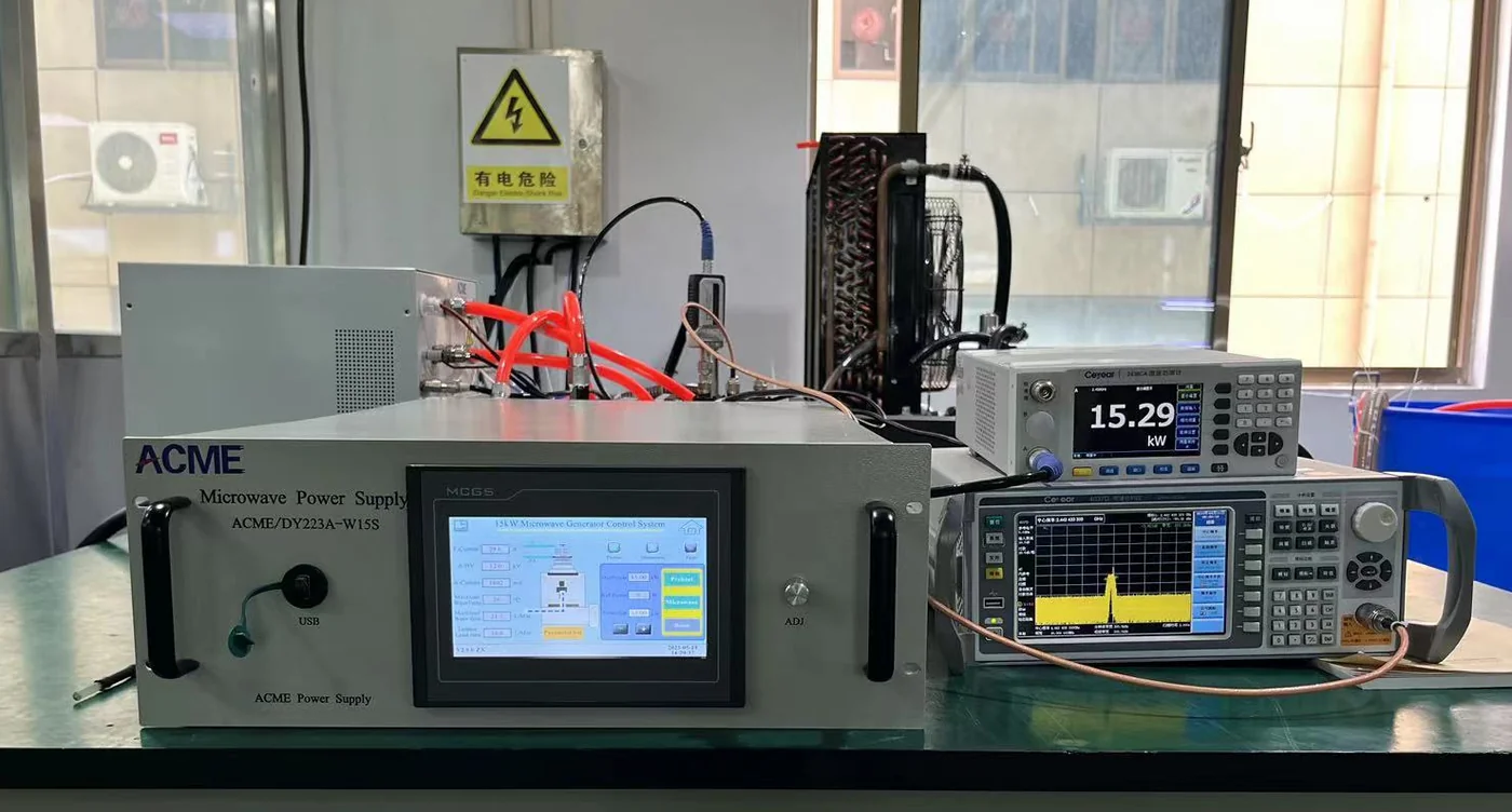
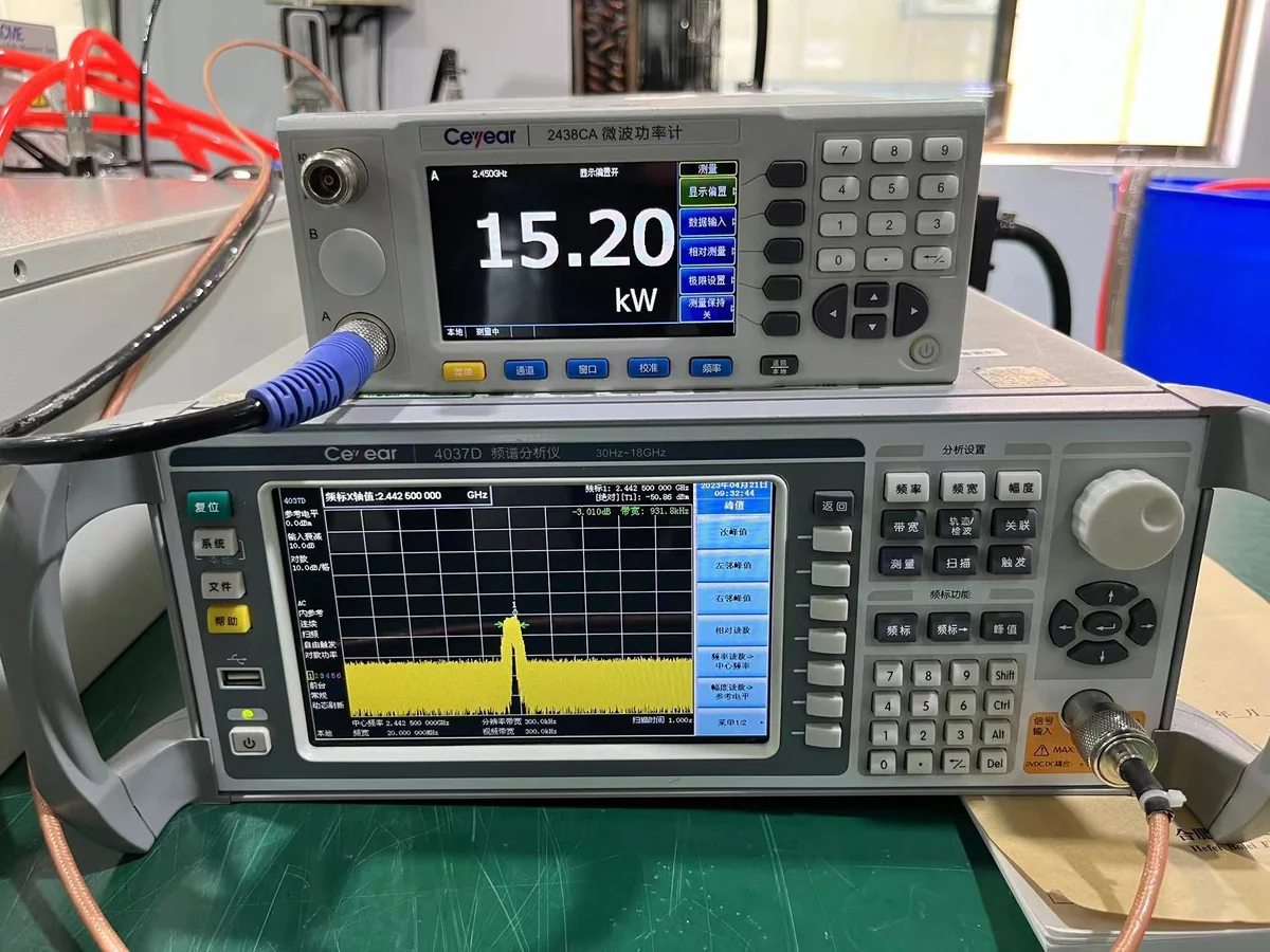
Verify the Agreed Control Functions Before Delivery
Agreed control, monitoring and protection functions can be included in the project verification scope. The test scope follows the selected generator configuration, supply boundary and technical agreement.
HMI操作
Confirm agreed operator functions through the selected local control interface.
Communication / Interface
Confirm agreed external-control interface functions for the selected project configuration.
监控
Confirm agreed status and monitoring functions available on the selected control package.
Protection / Interlocks
Confirm agreed protection and machine-interface functions under defined test conditions.
文件
Review the agreed interface and verification documents according to the project supply scope.
Verification can cover agreed operator functions, communication, monitoring, interlocks, alarms and protection behavior. Detailed procedures and engineering records remain project documents rather than public webpage content. These activities are verification, not a blanket product certification.
Request Control Verification Scope技术常见问题

Microwave Generator Control System FAQs
Direct answers to common PLC, HMI, communication, monitoring and protection questions for industrial microwave generator integration.
1. What is a microwave generator control system?
It is the control layer that operates and coordinates the microwave generator. Depending on the selected configuration, it can include local HMI operation, external automation, operating-status monitoring, alarms, interlocks and protection functions.
2. Can an SDACME microwave generator be controlled by a PLC?
Yes. PLC integration can be evaluated for OEM equipment. The final control boundary, communication method and required operating and safety functions are confirmed for the selected generator and project.
3. Do SDACME microwave generators support RS485?
RS485 is available on confirmed current SDACME microwave generator configurations. The applicable communication specification is confirmed for the selected model and project rather than published as one universal interface for every generator.
4. Is Modbus available for microwave generator control?
Modbus RTU is available on confirmed configurations. The applicable interface scope is reviewed for the selected generator and OEM project.
5. Can I use 0–10 V or 4–20 mA for microwave power control?
0–10 V and 4–20 mA can be evaluated as optional or project-configured analog interfaces where applicable. Final compatibility and implementation are confirmed during project engineering.
6. Does the control system support Ethernet, CAN-Bus or EtherCAT?
If your equipment requires Ethernet-based communication, CAN-Bus, EtherCAT or another industrial network, include it in the inquiry. Compatibility is reviewed for the selected control configuration and should not be assumed across the full product line.
7. What parameters can be monitored?
Depending on the model and control package, monitoring may include generator operating status, microwave-power information, selected electrical or cooling status, alarms and fault information. The final monitoring scope is confirmed for the selected configuration.
8. How does reflected-power or arc protection work?
Applicable configurations can use reflected-power and abnormal-load information as part of the generator protection strategy. Arc or load protection capability and the final protective response depend on the selected model, RF system and project configuration. Internal detection methods and protection settings are not public specifications.
9. How are E-stop and external interlocks integrated?
E-stop and external interlocks are coordinated with the complete machine safety architecture. The required interface and responsibility boundary are confirmed during project engineering.
10. What information should I send for a control-interface review?
Send the application, required frequency and power, customer PLC or HMI platform, preferred communication method, required monitoring and protection functions and any available integration documents. Detailed proprietary machine-control information is not required for the initial inquiry.
Have a project-specific control question?
Send the functional requirement first. Detailed engineering information can be reviewed at the appropriate project stage.
Technical Inquiry / RFQ
Request a Microwave Generator Control Configuration & Quotation
For an efficient first engineering response, send the control and interface information already available. You do not need to disclose complete PLC programs or internal machine-control logic at the inquiry stage; functional requirements and available interface documents are normally sufficient to begin the review.
Initial review can begin from functional requirements, equipment information and available interface documents. Detailed proprietary control information can be exchanged only when required during project engineering.
Send Your Control Requirements to SDACME
SDACME will review the applicable generator and control configuration and prepare the technical proposal and quotation scope. Detailed interface documents are exchanged as required during project engineering.
