工业微波发生器安全标准与合规指南
工业微波发生器的安全标准 保护范围不仅限于微波源本身。在实际设备架构中,需要评估安全、射频隔离、电磁兼容性、机械锁止、验证和目的地市场要求。这些要求取决于所选的发电机、工作频率、射频系统、安装方式以及最终的市场需求。.
安全与合规范围
设备级别上的安全性和合规性必须进行评估
工业级微波发生器是大型电力系统和射频系统的一部分,因此其合规计划需要兼顾这两者。 发电机本身 以及它如何被集成到最终的机器、安装和目的地市场中。.
合规范围随着供应边界的扩大而扩大
在选择标准、测试和文档要求之前,要明确规定要提供的内容。.
微波发生器
发电级电气、控制和保护功能。.
微波子系统
发电机与微波传输路径集成在一起。.
完整机器
微波子系统与机器安全体系结构进行了协调。.
安装与市场
最终运营环境和目的地市场要求。.
合规规划前应考虑的四点问题
及早确定这些输入数据有助于将发电机选择、机器集成、测试和文档编制与实际项目相匹配。.
正在评估哪些设备?
首先,确定要审查的设备的物理和合同边界。.
- 仅有发电机
- 微波发生器子系统
- 带有微波头的发电机和波导
- OEM机器集成
- 完善的加工设备
设备将安装在哪里?
目的地国家和安装环境会影响合规路径和技术要求。.
- 频繁使用
- 射频发射要求
- 市场准入程序
- 技术文档
- 安装要求和职业安全要求
需要哪些安全功能?
完整的机器风险评估应识别出允许或阻碍微波操作的条件。.
- 紧急停止
- 门锁或门禁系统
- 开启/关闭微波功能
- 与冷却相关的锁止装置
- 故障停机和安全重启
需要进行哪些 V确认?
确定协议设备范围所需的检查、测量和记录要求。.
- 电气检查和功能检查
- 安全锁接合验证
- 微波泄漏测量
- 适用的射频/电磁兼容性测试
- FAT、SAT 和项目文档
发电机的要求和整机要求是有联系的,但并不一定是相同的。. 首先确定设备边界,然后制定适用的安全、EMC、射频和市场合规计划。.
工业微波设备的关键标准和监管主题
工业级微波器件通常由 多个技术和监管层. 针对微波炉的安全、电磁兼容性排放、机器安全以及目的地市场的要求,分别涉及设备评估的不同部分。.
一个微波系统 — 多层合规性
与项目相关的标准取决于设备边界、机器架构和目标市场。.
适用的合规途径是以实际产品为基础构建的。. 必须综合考虑发电机设计、射频传输、机器防护、控制架构、电磁兼容性能以及市场需求。.
每个标准都贡献了什么
标准应根据其技术范围使用。 在系统层面上,它们的作用相互重叠,但不应将其视为可互换的证书。.
IEC 60519-1 & IEC 60519-6
安全IEC 60519-1 建立了工业电加热和电磁加工的一般安全框架。IEC 60519-6 在其范围之内增加了对高频介质加热和微波加热加工设备的特定要求,其中包括微波发生器。.
CISPR 11
EMCCISPR 11 是工业、科学和医疗设备的重要电磁兼容参考标准。该标准涵盖射频干扰排放,并为适用限值和测量方法提供了框架。.
FCC 第 18 部分
美国市场美国境内使用的工业级微波设备应根据适用的 FCC 第 18 部分要求进行评估。设备分类、频率使用、辐射以及适用的授权途径都是这一评估的一部分。.
ISO 13849-1 / IEC 62061
功能安全在设计和验证与安全相关的机器控制功能时,这些标准可能具有相关性。所需性能由定义的安全功能和完整的机器风险评估确定。.
标准并不自动就是产品证书。
标准提供技术要求、评估方法和工程框架。最终的合格证明取决于实际产品、适用的市场渠道以及佐证的验证证据。.
在测试之前确定合规路径
- 确定设备和供应的边界。.
- 确定目的地国家或地区。.
- 确定适用的安全和EMC要求。.
- 在需要时定义机器安全功能。.
- 制定测试方法和验收标准。.
- 确认所需的技术文件。.
没有任何单一的标准可以确定每个工业级微波炉安装设备的完整合规状态。. 构建标准和验证计划,以实际的发电机、射频系统、完整机器和目标市场为基础。.
2450 MHz 和 915 MHz 需要不同的监管审查
操作频率不仅影响微波系统的设计。 它也可能影响 频谱使用、干扰控制、设备评估以及目的地市场规划。. 因此,应从微波工程和监管的角度重新审视频率问题。.
广泛应用于工业微波系统
2450 MHz 频段广泛用于工业级微波的生成和处理。监管规划时仍应考虑整个设备以及该设备将安装或供应的市场。.
- 确认目的地国家的要求。.
- 审核适用的设备分类。.
- 控制排放超出预定工作范围。.
- 进行屏蔽和微波隔离的协调工作。.
- 定义最终的射频泄漏验证。.
- 查看本地安装要求。.
目的地市场必须尽早确认
915 MHz 不应被视为在全球范围内具有相同的监管可用性。需要根据预期目的地市场的需求来检查国家频谱规则和设备要求。.
- 确认目的地国家或地区。.
- 确认允许的频率范围。.
- 查看所计划的设备类别及其使用方式。.
- 评估适用的射频辐射要求。.
- 考虑当地的干扰环境。.
- 确认所需授权或文件。.
ISM 认证和市场合规是相关的,但并不是同一种决定。. 该项目还需要考虑设备分类、排放、安装、文件记录以及目的地国家的规定。.
频率选择既是射频决策,也是监管决策
合适的操作频率需要在技术上与工艺相匹配,同时还要符合预期设备和市场的要求。 这两项评估应该同时进行。.
微波工程
在完整的微波功率传递和处理体系结构中,选择频率。.
- 所需微波功率
- 工艺负载和材料行为
- 喷雾器或腔室设计
- 波导结构
- 匹配和反射功率管理
- 工艺一致性和操作策略
监管工程
确认所选频率和设备配置符合目的地市场合规计划的要求。.
- 目的地国家或地区
- 允许使用的频谱
- 设备分类
- 射频发射要求
- 适用授权途径
- 所需的技术文件
在最终频率选择之前,先定义这些输入。
早期确认可以降低设备设计已经完成之后更换发电机、波导或符合性计划的风险。.
目标市场
最终设备将安装、安装并运行的国家或地区。.
电源需求
工艺所需微波输出功率和预期运行范围。.
射频系统
微波头、波导、应用器、腔室和工艺负载配置。.
适用范围
发电机、子系统或整机的要求以及所需的文档。.
在 RF 设计完成之前,先确认目的地国家
为了 915 MHz工业微波项目, 在初始工程评审期间,提供目的地市场信息。随后,可以结合微波功率、波导和应用器选择,考虑频率可用性、射频发射要求以及适用的合规路径。.
将微波能量从源头控制到负载端
微波炉的安全取决于 完整的射频功率路径, 包括发生器、微波头、波导、接口、应用器或腔室以及可进入的开口。安全设备结合了射频屏蔽、访问控制、屏蔽以及最终验证。.
安全必须遵循完整的微波传输路径
微波源与工艺负载之间的每个接口都可能影响射频隔离、访问安全性和最终泄漏性能。.
RF 防护罩
围绕微波能量系统维护一个工程化的金属防护路径。.
波导连接件
正确安装法兰、连接和组装对于RF屏蔽非常重要。.
受保护访问
与设备保护和锁闭策略配合,协调门、盖板和维修通道的设置。.
屏蔽与过滤
管理电线、信号线和结构穿透孔周围的 RF 通道。.
泄漏 V检测
在组装好的设备上测量可接触到的射频屏蔽界限。.
最终的 RF 安全性是系统级的结果。. 仅靠发电机设计无法替代正确的波导组件、腔室屏蔽、访问控制以及最终的微波泄漏检测。.
将射频安全融入设备架构
机械工程、射频工程和机器控制应该支持相同的封隔策略,而不应将其视为独立的设计任务。.
微波隔离
该发电机、传输组件和工艺室构成了一个完整的射频屏蔽系统。连接处和开口处的构造细节会影响最终的泄漏性能。.
- 波导法兰和连接件
- 应用器和腔室接口
- 服务开通和渗透情况
- 门和可拆卸的盖子
屏蔽
用于限制微波系统周围非预期的射频能量的金属屏蔽。其有效性取决于安装的屏蔽箱、连接处、开口和接口。.
- 内阁和议会的结构
- RF 感应接入点
- 观察或过程的开放
- 机械连接件和接口
过滤与渗透
电力、信号、传感器和公用设施通过设备外壳进行必要的穿透。它们的安装应支持射频屏蔽和电磁兼容性性能。.
- 电源和信号接口
- 电缆布线
- 在适用时进行过滤
- 接地和连接的协调
安保与出入控制
对可能存在微波能量的区域的访问,应与完整的机器防护和联动策略进行协调。.
- 工艺门
- 维修访问权限
- 服务面板
- 安全防护接口和互锁接口
Verify 可访问性 RF 界限在组装设备上实现
微波泄漏测量应使用适用于设备和市场的适用测试方法和验收标准。在RF系统、室温箱、防护装置和接口组装完成之后,测量结果最为准确。.
考虑设备周围的人员分布情况
最终的安装应考虑适用情况。 职业性射频辐射暴露要求 一起 在正常的操作员位置、维修通道以及微波设备周围的其他受限区域时,最终曝露评估属于完整的安装系统安全计划的一部分。.
将微波源集成到设备安全体系结构中
工业级微波发生器应该仅在满足所需机器条件的情况下运行。该发生器的 控制、监测和保护接口 因此,需要与警卫、紧急停止功能、供电系统以及最终设备控制体系进行协调。.
微波操作取决于机器的特定条件。
完整的设备设计规定了何时允许使用微波加热,何时必须禁用微波加热,以及机器在遇到异常运行情况时应采取何种应对措施。.
访问条件
必要的防护装置、门或受保护的接入点处于规定的运行状态。.
冷却条件
所选的发电机和射频设备具备所需的冷却条件。.
控制权限
主机设备或控制系统提供所需的微波激活条件。.
无活动故障
控制系统已对要求对微波进行抑制或关闭的条件进行了评估。.
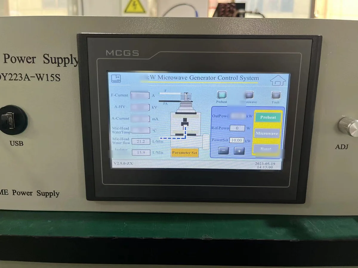
15 千瓦微波发生器 HMI 控制接口
发电机的运行状态和控制功能支持设备集成。最终的机器安全体系结构是围绕整个系统和所需的安全功能构建的。.
Key Machine-Safety Functions to Coordinate
The exact implementation depends on the final machine risk assessment, operating sequence and equipment architecture. These functions should be defined during system integration rather than added after installation.
紧急停止
The machine emergency-stop strategy should bring microwave operation to the defined safe condition as part of the complete equipment stopping architecture.
Guard Interlock
Doors, covers or other guards protecting areas where microwave energy may be present can be coordinated with the microwave operating permission.
微波开启/关闭
The equipment control system should establish the conditions under which microwave generation is permitted and the conditions that require microwave power to remain inhibited.
冷却条件
Where microwave generator or microwave-head operation depends on cooling, relevant cooling conditions can be incorporated into the equipment interlock strategy.
Fault Handling
Equipment faults should produce the defined machine response and provide appropriate status information to the operator or host control system.
Restart Strategy
Restart behavior following an interruption, safety demand or equipment fault should be defined from the machine risk assessment and operating sequence.
Coordinate Electrical Protection with the Installation
Industrial microwave systems combine electrical power, control circuits and microwave-generation hardware. Electrical protection should therefore be evaluated against the selected equipment and complete installation.
Generator Interfaces and Machine Safety Work Together
A microwave generator provides part of the control and protection architecture. The final machine integrates those interfaces with the rest of the equipment.
Control, Status & Protection Interfaces
The microwave subsystem provides defined operating, monitoring and protection functions that can be coordinated with the host machine during OEM integration.
Guards, E-Stop, Utilities & Safety Architecture
The equipment integrator coordinates generator interfaces with guarding, emergency stop, utilities, process equipment and the defined machine safety functions.
A generator interlock input is one element of a larger machine-control architecture. The required safety response is defined by the hazard, complete safety function and machine risk assessment.
PL and SIL Apply to Defined Safety Functions
Performance Level and Safety Integrity Level are used when engineering defined safety-related control functions. They should not be treated as generic ratings automatically assigned to a microwave generator simply because the generator provides an interlock or enable input.
Start with the Safety Function — Not the Generator Label
A safety-related function is defined from the hazard, required machine response and complete control architecture. Sensor inputs, logic, output elements and the microwave source may all form part of the same safety chain.
Build Functional Safety from the Risk Assessment
The engineering process begins with the machine and the hazard. Only after the required safety function has been defined should the required performance and control architecture be selected.
Identify the Hazard
Identify hazardous situations associated with microwave energy, electrical energy, machine access, moving equipment, utilities or other process-specific hazards.
Risk AssessmentDefine the Safety Function
Define what the equipment must do when a safety condition occurs, such as preventing or removing microwave generation.
Required ResponseDetermine Required Performance
Determine the required performance of the defined safety function using the applicable machinery-safety methodology.
PLr / SILDesign the Safety Chain
Coordinate sensing, safety-related control logic, output elements and the microwave source as one complete function.
建筑Verify & Validate
Confirm that the implemented safety function achieves its defined response and required performance in the complete machine.
ValidationEvaluate the Complete Safety-Related Control Chain
The exact components and architecture depend on the machine design and required safety function.
Sensor / Safety Device
Guard switch, emergency-stop device or other sensing element used by the defined safety function.
Safety-Related Control Logic
Evaluates the safety demand and generates the required control response.
Final Switching / Control Element
Executes the required output action within the safety-related machine-control architecture.
微波源
Microwave generation is enabled, inhibited or otherwise controlled according to the defined machine response.
The complete implemented function must be evaluated. Validation is not limited to confirming that a single generator interlock input changes state.
ISO 13849-1 and IEC 62061 Address Safety-Related Control Functions
Both frameworks can be relevant to machinery functional safety. The appropriate methodology depends on the complete equipment, customer specification and applicable conformity strategy.
ISO 13849-1
Performance Level Approach
ISO 13849-1 provides a methodology for designing and integrating safety-related parts of control systems that perform defined machine safety functions.
- Begin with the defined machine safety function.
- Determine the required performance for that function.
- Evaluate the complete safety-related control architecture.
- Verify and validate the implemented function.
IEC 62061
SIL-Based Machinery Approach
IEC 62061 provides requirements and recommendations for the design, integration and validation of safety-related control systems used to carry out safety functions on machinery.
- Define the required machine safety function.
- Establish the required integrity for that function.
- Design the safety-related control system.
- Validate the complete implemented function.
“The Generator Has an Interlock, Therefore the Machine Is PL d / SIL 2”
An interlock interface alone does not define the performance of the complete machine safety function. The sensing device, control logic, output architecture and implemented response also need to be considered.
Define the Safety Function, Required Performance and Complete Architecture
Treat the microwave-generator interface as one part of the machine safety-related control system. Then evaluate the complete function against the selected functional-safety methodology.
Example Microwave-Related Safety Functions
These examples illustrate how a project can define a safety function. The actual architecture and required performance remain specific to the machine and its risk assessment.
Prevent Microwave Generation When Protected Access Is Open
A protected door or guard condition can be used as part of a defined safety function that prevents microwave generation when access is not in the required operating state.
Remove Microwave Power Following an Emergency-Stop Demand
The machine stopping concept can include a defined response for microwave generation following activation of the applicable emergency-stop function.
Prevent Operation Until Required Safety Conditions Are Satisfied
Microwave enable can be coordinated with defined machine safety conditions so the RF source remains inhibited until the required operating state has been established.
A microwave-generator interlock is an interface within the machine safety architecture. PL or SIL applies to the defined safety function and its complete implementation, including sensing, logic, output control, microwave-source response and validation.
Manage RF Emissions and Electromagnetic Immunity
Industrial microwave equipment intentionally generates high RF power. EMC engineering therefore needs to distinguish intended microwave energy from unintended conducted or radiated disturbances, while also considering how the equipment responds to electromagnetic interference from its environment.
Separate the Intended RF Path from Unwanted Emission Paths
EMC performance depends on the complete equipment construction, electrical interfaces, RF transmission path and final installation.
Emissions and Immunity Are Different EMC Questions
Both may be relevant to an industrial microwave project, but they evaluate different interactions between the equipment and its electromagnetic environment.
射频辐射
Emission assessment considers unintended conducted and radiated RF disturbances from the assembled equipment under the applicable operating and measurement conditions.
- Conducted RF disturbance
- Radiated RF disturbance
- Off-band emissions
- Equipment operating conditions
- Applicable measurement arrangement
Electromagnetic Immunity
Immunity evaluation considers whether the equipment continues to operate safely and appropriately when exposed to specified electromagnetic disturbances.
- Electrostatic or electrical disturbance
- RF electromagnetic disturbance
- Power-related disturbances
- Control-system behavior
- Defined performance criteria
Factory Measurement Supports Engineering Verification
Generator-level power and spectrum-related measurements can provide useful factory engineering evidence during production and functional verification.
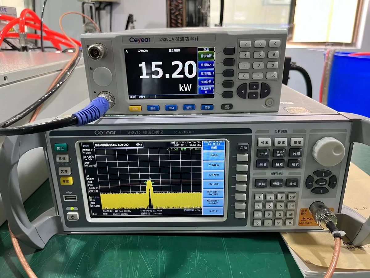
15 kW Microwave Generator Power & Spectrum-Related Test
Factory measurement evidence from a 15 kW industrial microwave generator. Formal regulatory EMC testing follows the applicable standard, equipment configuration and compliance route.
EMC Performance Depends on More Than the Generator
Final EMC behavior can change when the generator is integrated into a cabinet, machine, process chamber and site electrical environment. Several engineering factors need to work together.
Cabinet Shielding
Enclosure structure, openings and joints influence radiated-emission control.
Power-Line Filtering
Power interfaces may require appropriate filtering and installation coordination.
Signal Interfaces
Signal cable selection, filtering and routing influence conducted and radiated coupling.
Grounding & Bonding
Ground and bonding implementation form part of the complete installed EMC architecture.
Waveguide Interfaces
RF joints and mechanical interfaces influence microwave containment and unwanted RF paths.
电缆路由
Separation and routing of power, control and signal cables can affect EMC performance.
设备布局
Physical arrangement can influence coupling paths and the effectiveness of protective measures.
Final Installation
Site wiring, grounding and integration can affect the final equipment EMC result.
EMC Performance Belongs to the Assembled Configuration
Cabinet modifications, cable changes, waveguide routing, grounding and equipment layout can influence final EMC behavior. Generator-level engineering therefore needs to be coordinated with machine integration and the configuration used for final compliance verification.
CISPR 11 emission requirements, applicable immunity requirements and generator factory measurements answer different engineering questions. Define the formal EMC test plan around the actual equipment, operating condition and destination market.
Define Compliance Requirements for the Destination Market
Market compliance should be considered before the final equipment design is frozen. The applicable route depends on what product is being supplied, where it will be placed on the market and which requirements apply to that product.
Start with the Product Scope and Destination Market
A microwave generator, an RF subsystem and a complete industrial machine can have different compliance responsibilities. Define the product boundary first, then identify the applicable safety, EMC, RF, documentation and market-access requirements.
European Union and United States Follow Different Compliance Routes
The following workflows illustrate the engineering sequence. The exact requirements still depend on the final product, configuration and intended market.
欧盟
Build conformity around the actual product and the EU requirements applicable to that product.
Define the Product Scope
Identify whether the supplied item is a generator, microwave subsystem or complete machine.
Identify Applicable EU Requirements
Determine which EU product rules and essential requirements apply to the actual equipment.
Risk & Technical Assessment
Identify relevant hazards, technical requirements and applicable standards.
Verification & Test Evidence
Complete the inspections, calculations and tests required by the conformity plan.
Technical Documentation
Compile the technical information needed to demonstrate conformity of the product.
EU Declaration of Conformity
Where required, the responsible manufacturer prepares and signs the applicable declaration.
CE Marking
CE marking is applied where the applicable EU product rules require it and the required conformity process has been completed.
美国
Review industrial microwave equipment within the applicable FCC Part 18 ISM framework.
Define the Equipment Scope
Identify the RF equipment being supplied and how it is intended to be used.
Confirm ISM Classification
Determine whether the equipment falls within the applicable FCC Part 18 ISM category.
Review FCC Part 18
Identify the requirements applicable to the selected industrial microwave equipment.
Frequency & RF Emissions
Evaluate operating frequency, applicable emission requirements and RF-control measures.
Technical Requirements
Address applicable construction, labeling, information and documentation requirements.
设备授权
遵守 FCC 规定适用于设备类别的相关授权程序。.
Supplier's Declaration of Conformity
Non-consumer ISM equipment is subject to the FCC Supplier's Declaration of Conformity procedure under the applicable Part 18 rules.
CE Marking Is a Conformity Process — Not a Generic Certificate
Correct terminology matters when specifying or purchasing industrial microwave equipment for the European market.
Avoid Treating “CE Certified” as a Universal Generator Specification
CE marking applies to products covered by applicable EU legislation that requires the marking. The responsible manufacturer evaluates the actual product against the relevant requirements and maintains the supporting conformity documentation.
Build Evidence Around the Actual Product
Depending on the applicable product rules, the technical documentation can include information such as:
非消费类ISM设备采用SDoC授权程序
针对美国市场设计的工业级微波设备,应根据适用的 FCC 第 18 部分的要求进行评估。对于非消费级 ISM 设备,目前的设备认证方式是供应商的符合性声明程序。.
Enclosure Protection Must Match the Installation
Market compliance also depends on the actual physical equipment configuration. Enclosure protection should therefore be selected from the real site and installation conditions.
Do Not Assume One IP Rating for Every Generator Configuration
The required enclosure protection depends on the selected cabinet, cooling arrangement and installation environment. Any stated IP rating should therefore match the specific product configuration and supporting evidence.
Three Compliance Terms That Should Not Be Confused
Clear terminology helps OEMs and procurement teams specify exactly what evidence they need from a microwave-equipment supplier.
Standard
A technical standard defines requirements, methods or engineering guidance for a defined scope. Referencing a standard is not automatically the same as holding a product certificate.
测试证据
Test reports and verification records demonstrate specific characteristics of a defined product configuration under the stated test conditions.
Market Conformity
Market conformity combines the applicable legal framework, product scope, assessment route, technical evidence and required manufacturer or responsible-party documentation.
Compliance follows the actual product and destination market—not a generic “CE/FCC certified microwave generator” label. Define the equipment scope, applicable requirements, verification evidence and documentation route before final market claims are made.
Convert Safety Requirements into a Testable Verification Plan
Safety and compliance requirements become useful engineering criteria when they can be translated into design reviews, functional checks, measurements, acceptance criteria and documented evidence. The verification plan should match the actual equipment scope and project requirements.
Six Stages from Requirement Review to Acceptance
Not every project requires the same tests. Define the verification matrix from the equipment boundary, destination market and customer specification.
Risk & Requirement Review
Define the equipment boundary, destination market, safety functions, applicable technical requirements and required acceptance evidence.
Design Review
Review relevant electrical architecture, RF transmission, shielding, cooling, interfaces and machine-integration requirements before final build.
Electrical & Functional Checks
Verify the agreed electrical, operating, control and protection functions for the supplied equipment.
Interlock & Safety Verification
Check the defined emergency-stop, guard, enable, cooling and fault-response functions within the agreed equipment boundary.
RF & EMC Verification
Perform the RF, leakage, emission, immunity or related checks required by the specific project and compliance plan.
FAT / SAT & Documentation
Complete the agreed acceptance activities and provide the project documentation required for shipment, installation or final handover.
Functional Verification Before Project Handover
Factory functional testing can verify the agreed generator-level operating and protection functions before shipment. The exact test scope should be defined from the supplied configuration and customer acceptance requirements.
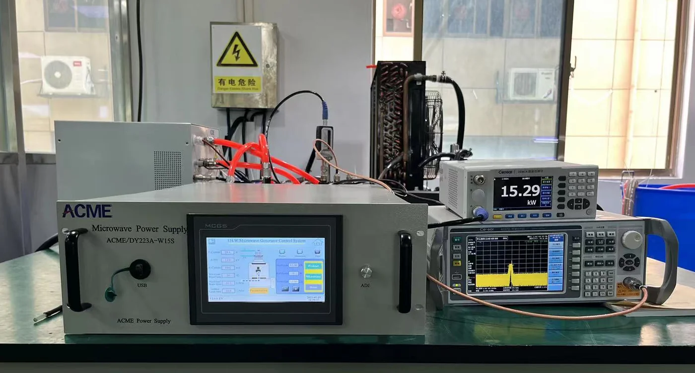
15 kW Microwave Generator Functional Test
Factory functional verification of a 15 kW industrial microwave generator. Project acceptance requirements are defined according to the supplied equipment and agreed test plan.
Build a Verification Matrix Around the Actual Project
A useful acceptance plan identifies what will be checked, where it will be checked and what evidence will be recorded. Generator-level factory testing and complete-machine testing may therefore have different scopes.
Define Required Records Before Shipment
Documentation expectations should be agreed early enough that required inspections, measurements and records can be incorporated into the project verification process.
Move from Compliance Planning to an Agreed Acceptance Test Matrix
MW-P18 defines why safety, RF, EMC and documentation requirements need verification. For a deeper review of factory acceptance, site acceptance and project test planning, continue to the dedicated microwave-generator FAT / SAT page.
Define the verification matrix before shipment. This keeps engineering requirements, acceptance criteria, responsibilities and documentation expectations aligned between the microwave-equipment supplier, OEM integrator and final project.

Industrial Microwave Generator Safety & Compliance FAQ
These answers address common questions about industrial microwave safety standards, RF leakage, EMC, machine interlocks, PL/SIL, CE marking and FCC Part 18 when integrating a microwave generator into industrial equipment.
Industrial microwave safety is evaluated at system level. The applicable standards, RF controls, machine safety functions, EMC tests and market-compliance requirements depend on the generator, RF path, complete machine, installation and destination market.
01 What safety standards apply to industrial microwave generators?
The applicable standards depend on the equipment boundary and final machine configuration. IEC 60519-1 provides a general safety framework for electroheating and electromagnetic processing equipment, while IEC 60519-6 addresses particular requirements for high-frequency dielectric and microwave heating and processing equipment.
Machine safety, functional safety, EMC and destination-market requirements may introduce additional applicable standards and regulatory requirements.
02 What is IEC 60519-6?
IEC 60519-6 is the microwave-specific part of the IEC 60519 safety framework. It addresses particular safety requirements for high-frequency dielectric and microwave heating and processing equipment.
It is used together with the relevant general safety requirements rather than as a stand-alone statement that an entire machine is automatically compliant.
03 What does CISPR 11 cover for industrial microwave equipment?
CISPR 11 addresses radio-frequency disturbance emissions from industrial, scientific and medical equipment. It provides requirements related to applicable emission limits and measurement methods.
EMC immunity is a separate question and should be evaluated under the applicable immunity requirements for the final product and environment.
04 Is CISPR 11 a certification?
No. CISPR 11 is a technical EMC emissions standard, not a generic product certification. Compliance claims should be based on the actual equipment, applicable test configuration, measurement method and supporting evidence.
05 Does FCC Part 18 apply to industrial microwave generators in the United States?
FCC Part 18 is the relevant U.S. regulatory framework for industrial, scientific and medical equipment that generates and uses RF energy for ISM purposes.
应对实际设备进行评审,以确定其分类、运行频率、排放量以及适用设备授权要求。.
06 Is a 915 MHz industrial microwave generator permitted worldwide?
No. 915 MHz should not be assumed to have identical regulatory availability worldwide. The 902–928 MHz ISM allocation is associated with ITU Region 2, while national spectrum and equipment rules still need to be checked for the final destination.
For a 915 MHz project, the destination country should therefore be identified before the RF system design is finalized.
07 What is a microwave generator safety interlock?
A safety interlock is part of the control architecture used to permit or inhibit microwave operation according to defined equipment conditions.
Typical conditions may include protected access, machine enable, cooling availability or other project-defined operating conditions. The complete machine determines the final safety function.
08 How should a microwave chamber door interlock be designed?
The interlock should be designed from the machine risk assessment and the required safety function. The protected access condition, safety-related control logic, output action and microwave-source response need to be evaluated as one complete function.
The required architecture and performance cannot be determined from the microwave generator alone.
09 Does a microwave generator need a PL or SIL rating?
PL or SIL normally applies to a defined machine safety function and its complete implementation, not automatically to the microwave generator as a whole.
A generator interlock or inhibit interface can be one part of a safety-related control chain that also includes sensing, safety logic and final control elements.
10 How is microwave leakage measured on industrial equipment?
Microwave leakage is measured at accessible RF containment boundaries using the applicable test method and acceptance criteria for the equipment.
Relevant inspection locations can include:
- Waveguide flanges and joints
- Applicator or chamber interfaces
- Protected access doors
- Observation windows
- 服务面板
- Other project-specific RF openings
Final measurement is most meaningful on the assembled microwave system.
11 What affects EMC performance in an industrial microwave system?
EMC performance depends on the complete installed configuration, not only on the microwave generator. Important factors can include:
- Cabinet shielding
- Power-line filtering
- Signal interfaces
- 接地和连接
- Waveguide joints
- 电缆布线
- Equipment layout
- Final site installation
12 What is an EU Declaration of Conformity?
An EU Declaration of Conformity is the manufacturer's declaration that the identified product meets the applicable EU requirements covered by the declaration.
It forms part of the applicable conformity process together with product identification, technical documentation and supporting assessment evidence.
13 Is “CE certified microwave generator” the correct terminology?
“CE certified” is not the best general description of the EU conformity process. CE marking is applied to products that fall under applicable EU legislation requiring the marking after the required conformity assessment and documentation process has been completed.
The correct assessment depends on the actual product being supplied and the EU requirements applicable to it.
14 What IP rating does an industrial microwave generator require?
There is no single IP rating that automatically applies to every industrial microwave generator. The required enclosure protection depends on the specific cabinet, cooling arrangement and installation environment.
Indoor or outdoor use, dust, moisture, ambient conditions and service requirements should be considered when defining the enclosure configuration.
15 What information is needed for a microwave generator compliance review?
Start with the actual equipment configuration, operating frequency and destination market. Useful project information includes:
- Generator power and frequency
- 2450 MHz or 915 MHz operation
- 目的地国家或地区
- Generator, subsystem or complete-machine scope
- Microwave head and waveguide configuration
- Applicator or process chamber
- Electrical supply
- Cooling arrangement
- Machine safety and interlock requirements
- Required RF / EMC tests
- FAT / SAT requirements
- 所需的技术文件
Compliance Starts with the Actual Equipment
There is no single safety or compliance label that defines every industrial microwave project. Start with the equipment boundary, frequency, RF architecture, machine safety functions, installation and destination market, then build the applicable standards, verification and documentation plan.
Have a Safety, EMC or Market-Compliance Requirement?
Send your generator power, frequency, destination market, equipment scope and required tests for an engineering review.
Send Your Microwave Project Requirements for Engineering Review
Provide the core project information so the generator, RF architecture, safety interfaces, verification plan and destination-market requirements can be reviewed against the actual equipment scope.
You Do Not Need a Finished Compliance Specification to Contact Us
Start with the information already available. Open technical items can then be identified during the engineering review.
Include These Project Inputs Where Available
The required detail depends on whether the project involves a generator, microwave subsystem, OEM integration or complete industrial equipment.
微波发生器
Define the required microwave source and main operating range.
目标市场
Identify where the equipment will be placed, installed or operated.
射频系统
Describe how microwave energy will be transferred to the process.
Electrical & Installation
Provide the available site and utility conditions for integration.
机器安全
Identify the machine interfaces and safety-related functions relevant to microwave operation.
EMC & RF Verification
State any specified RF, leakage, emission or immunity requirements.
FAT / SAT Requirements
Define the expected factory and site acceptance scope where known.
Required Documentation
Identify the documents expected with the equipment or project.
From Project Inputs to an Engineering Scope
The objective is to identify the generator configuration, integration boundary and verification requirements early, before critical RF, machine or compliance decisions are locked.
Review Project Inputs
Confirm power, frequency, destination market, equipment boundary and process requirements.
Define Engineering Interfaces
Identify RF, electrical, cooling, control and machine-integration requirements.
Align Verification Scope
Establish the required tests, acceptance activities and project documentation.
Send the Available Project Information to SDACME
Include your required microwave power, frequency, destination market, RF system and any known safety, EMC or acceptance requirements. The engineering discussion can then focus on the actual project configuration.
