
915 MHz 高功率 微波发生器
SDACME提供基于磁控管的连续波电源 915 MHz 微波发生器系统 适用于高功率工业设备,以及 OEM 集成和项目化流程系统。.
目前已公布的路线包括: 25 kW、75 kW 和 100 kW, 与 可配置为30 kW的项目选项 经技术审核后即可提供。 电源选择应结合应用、波导接口、反射功率条件、冷却、现场供电、控制系统和目的地国家等因素进行评估。.
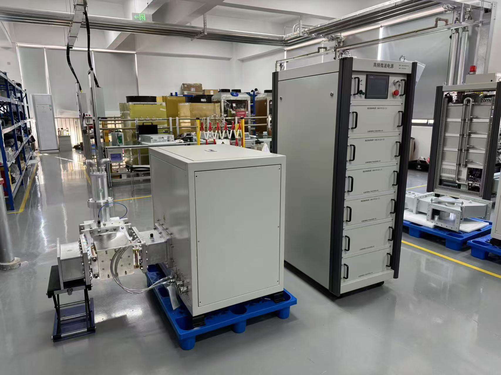
什么是915 MHz 微波发生器?
A 915 MHz 微波发生器 转换器 将电能转化为高功率微波能量,用于将能量输送至应用设备、工艺室或其他工程设备。SDACME 的当前 915 MHz 范围采用连续波磁控技术,适用于高功率工业设备、OEM 集成和项目化系统。.
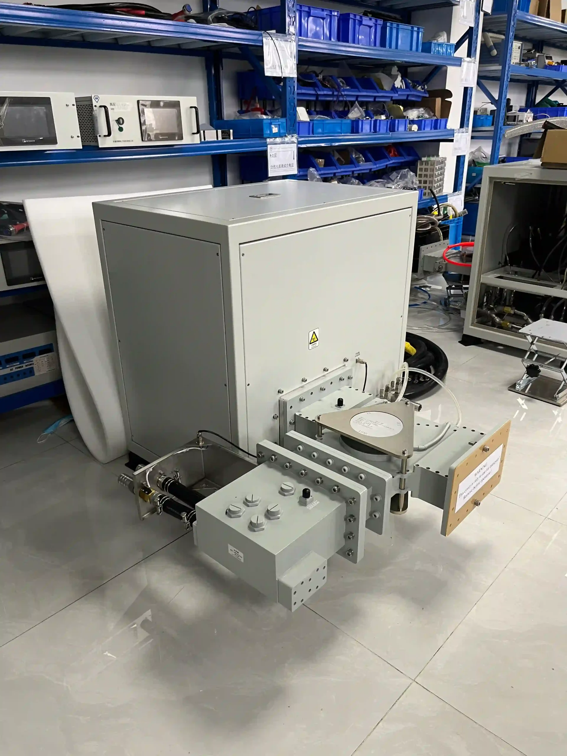
专为项目级微波集成而设计
在高功率下的微波源应作为完整设备的组成部分进行评估,而不应仅从额定功率 kW 中选择。.
在确认最终配置之前,应先对微波功率、波导导线布置、反射功率条件、冷却能力、现场供电和控制接口进行综合评估。.
连续波操作
基于磁控管的高功率微波源结构。.
25–100 kW 产品路线
25 kW、75 kW 和 100 kW 的可供选择的型号路线,以及 30 kW 的项目配置。.
系统级工程
RF、电气、冷却和控制接口将一起评估。.
从站点功率到过程负载
确切的供货范围取决于所选的型号。 射频配置和项目要求。.
电力与控制
电气转换、高压供电、操作控制和保护功能。.
微波头
磁控管和微波生成结构产生高功率的射频输出。.
RF 传输路径
根据需要配备隔离、反射功率处理、监测和波导组件。.
应用器/负载
客户或项目设备已连接在商定的微波接口上。.
在最终选择之前确认 915 MHz 的适用性
频率分配和设备要求因地区而异。因此,在最终确定 915 MHz 系统配置之前,应确认目的地国家和预期用途。.
比较 25 kW、30 kW, 75 kW 和 100 kW
应将额定功率作为首要筛选标准,然后根据负载、波导接口、反射功率条件、冷却系统、现场供电需求以及控制要求,确认完整的 915 MHz 配置。.
所选型号或项目配置的精确输出范围、频率容差、尺寸、冷却要求以及通信功能均已确认。.
25 千瓦 915 MHz 微波发生器
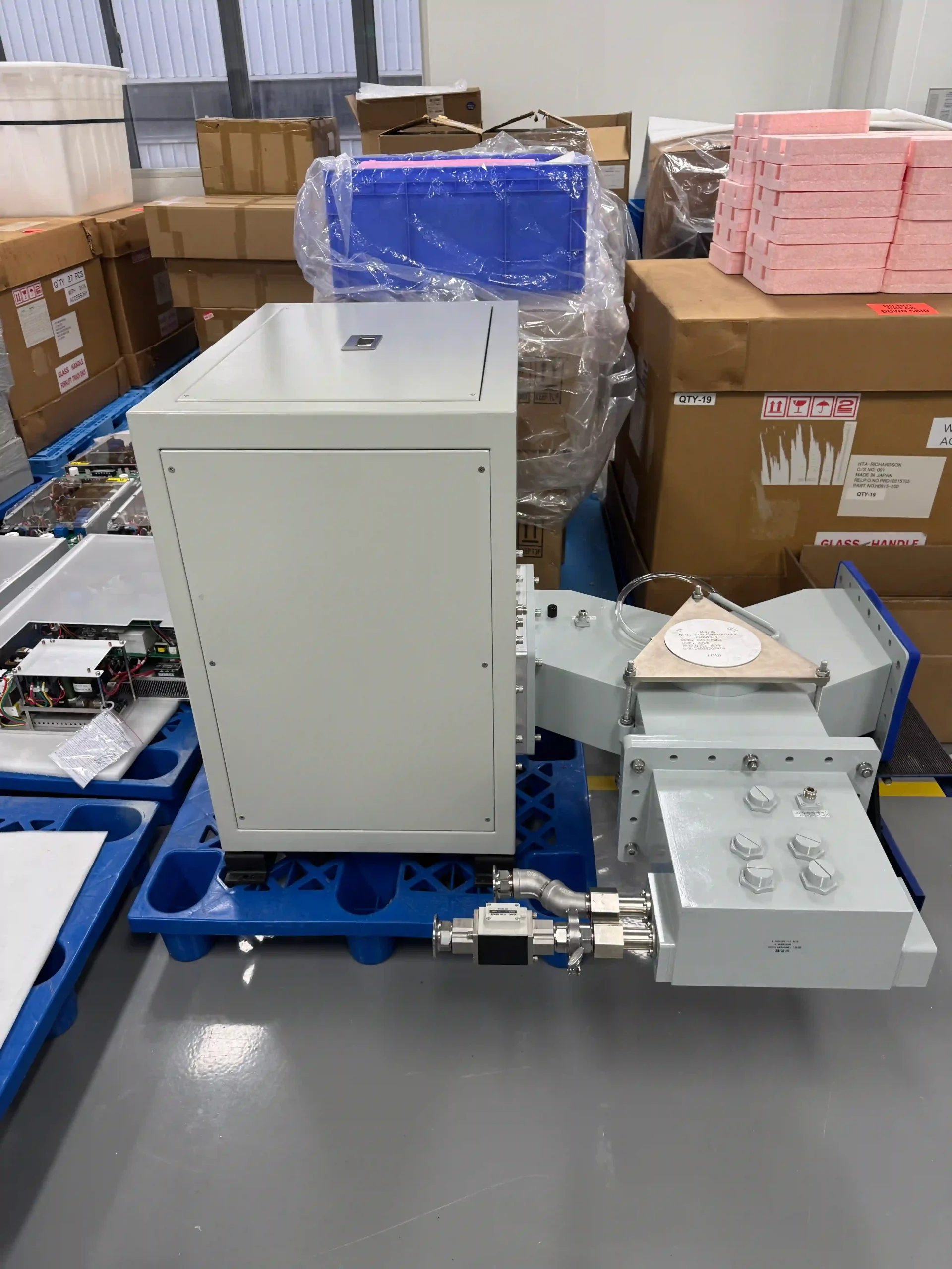
适用于工业设备的额定功率为 25 千瓦的路线 针对 OEM 集成和项目系统所需的低功率等级,属于 915 MHz 高功率系列的产品。.
- 波导和法兰接口
- 冷却用水需求
- 控制和通信接口
- 网站电气和安装条件
30 kW 项目配置
技术评审期间将确定 RF、电气、冷却、机械和控制方面的细节。.
如果项目需要这种功率等级,且最终配置取决于实际设备和现场条件,则可以考虑选择 30 kW 的 915 MHz 选项。.
- 应用和目标微波功率
- 加载信息、腔室信息或喷嘴信息
- 波导/法兰要求
- 冷却、控制和现场功率数据
75 kW 915 MHz 微波发生器
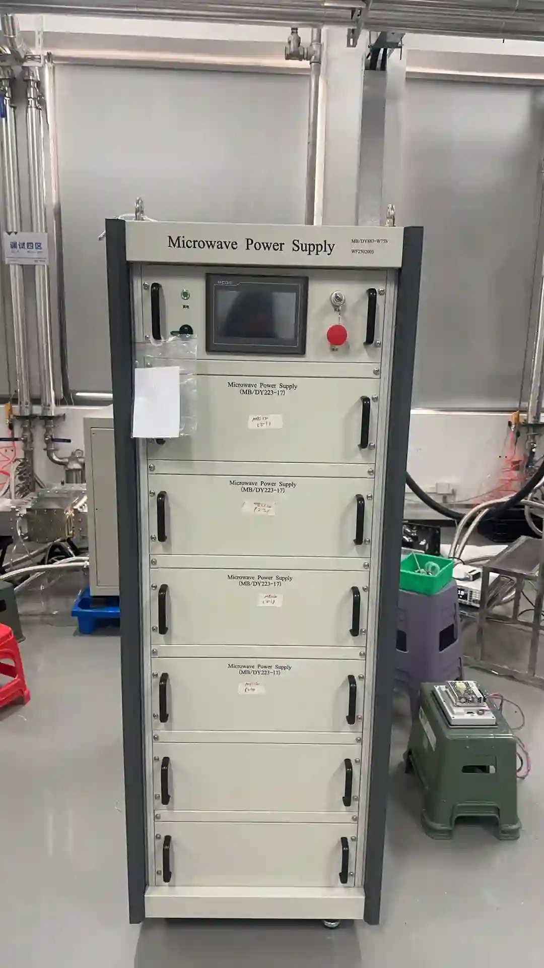
适用于需要项目级射频、电气、冷却和控制集成的高功率工业和 OEM 系统。.
100 kW 915 MHz 微波发生器
高功率项目集成
对于需要详细评估现场供电、射频集成、冷却和安装条件的高功率系统,推荐使用额定功率为 100 kW 的线路。.
- 可用电力容量
- 冷却系统容量
- 波导和射频配置
- 控制、保护和安装范围
四问有助于缩小电力输送路线
需要多少微波功率?
提供现有微波源的目标功率或额定功率。.
微波能量来自什么?
描述载荷、应用器、腔室、工艺系统或现有设备。.
RF 系统将如何连接?
提供 BJ9/波导配置、法兰方向以及现有 RF 组件。.
该站点是否支持这种功率级别?
在最终配置之前,应确认电气容量和冷却条件。.
包含在“A”中的内容 915 MHz 微波发生器系统?
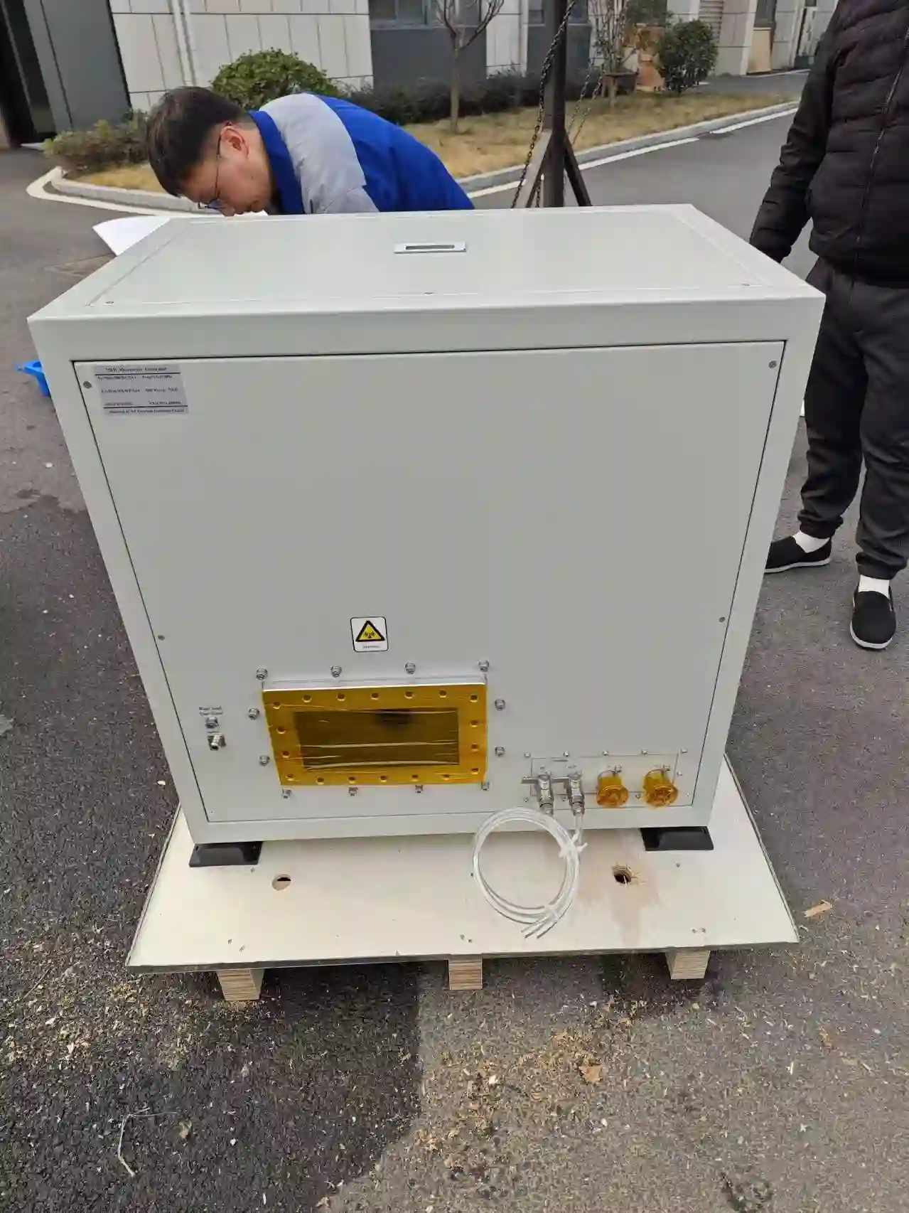
高功率微波源不仅仅是一台额定功率为 kW 的电源柜。完整的安装通常结合了电力转换、微波生成、射频传输、反射功率管理、控制、冷却以及客户的工艺设备。.
电源柜和微波炉头构成核心电源
微波发生器核心组件通常将电力和控制部分与微波发生器头以及它们之间的所需连接器结合在一起。.
因此,在微波头之外的 RF 通道需要根据选定的模型、工艺设备和项目要求进行配置。因此,需要确认导波路设计、反射功率处理和辅助 RF 组件的性能,而不能仅根据频率和额定功率进行假设。.
电力转换、运行控制、监测和保护功能。.
基于磁控管的发射器组件,产生 915 MHz 的微波输出。.
柜体、微波头和协议设备接口之间的连接要求。.
高功率微波系统体系结构
最终的 RF 组件列表和接口配置都由所选的生成器和项目定义。.
现场电气供应
客户设施的供电功率以协议的电压、频率和功率容量为准。.
网站侧面电源和控制柜
它转换和管理电力,同时提供操作控制和保护功能。.
生成器核心微波头
基于磁控管的装配装置产生高功率的 915 MHz 微波能量。.
生成器核心射频传输与保护
项目配置的波导和反射功率处理组件将源信号连接到负载。.
项目范围喷雾器/室
工业过程设备接收并将微波能量耦合到实际工艺负载中。.
过程方面项目供应可以包含哪些内容?
报价应该明确规定每个项目的实际边界,而不是依赖于通用软件包名称。.
微波源包
- 动力和控制柜
- 微波产生头
- 所需的柜体与主机的连接
- 针对特定模型的操作和保护功能
射频传输组件
- 波导段和过渡
- 反射功率处理组件
- 在需要时监控组件
- 在设计中包含调谐或负载组件时
接口协调
- RF接口的审查
- 本地/远程控制要求
- 设备互锁协调
- 配置前对安装数据进行审核
工艺设备和现场设施必须单独定义
在选择过程中,应确定接收微波能量的工艺设备。.
V电压、频率、可用容量、接地 并且安装条件也需要确认。.
制冷器或工厂冷却系统必须符合选定的高功率配置。.
应审查可用空间、设备布局、波导路径和维修通道。.
在可用时发送现有设备布局
对于新的 OEM 项目或改装项目,在报价之前,图纸和照片有助于确定 RF 接口和实际供电范围。.
在使用微波接口之前请先阅读本指南 设备集成
微波输出接口是高功率915 MHz安装的关键部分。目前发布的25 kW、75 kW和100 kW型号路线使用BJ9作为输出接口参考,而选定的型号和项目所需的最终法兰几何形状、方向和射频布置仍需确认。.
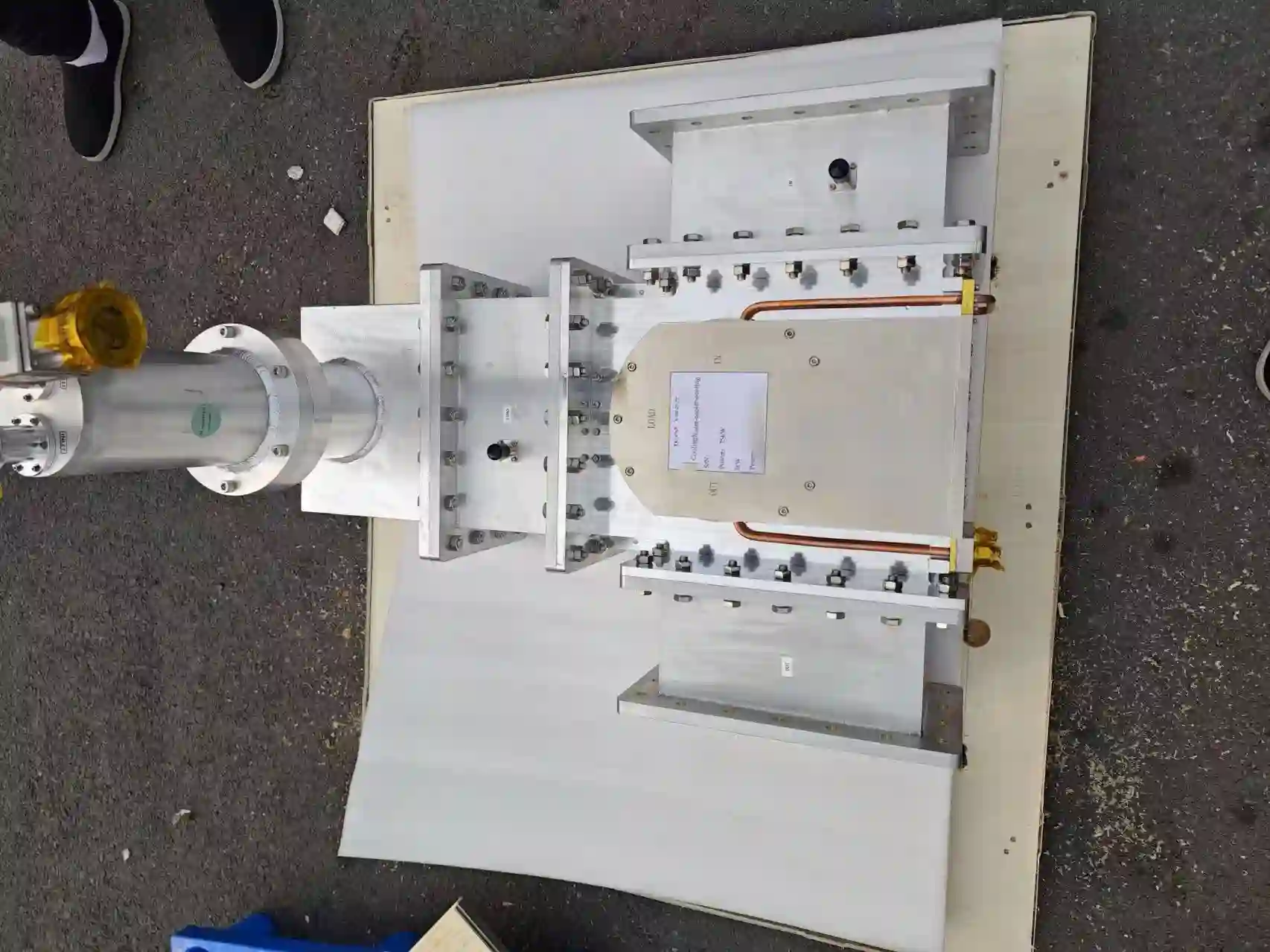
BJ9 是一个接口参考标准,而非完整的兼容性测试
匹配的频率和波导标识仅仅是集成评估的起点。机械连接、法兰细节、微波头定位、波导导线布置以及设备级耦合安排也应与实际安装相匹配。.
当该发电机被集成到现有腔室、应用器或高功率微波线中时,这一点就变得尤为重要。.
适用于目前发布的 25 千瓦功率等级 75 kW 和 100 kW 型号路线。.
对于所选的配置,应检查连接尺寸和机械细节。.
从微波头到处理负载的路径应视为一个完整的整体。.
在完成 RF 连接之前需要确认的六点
这些检查对于新一代 OEM 设备和现有设备更换项目都很有用。.
波导和护板
在微波输出处确认导波导参考、法兰几何结构、螺栓配置和机械连接。.
微波头的方向
检查微波炉的安装位置是否与设备相对应,以及所建议的安装方向是否符合现有安装空间。.
波导路径
检查源设备与处理设备之间的距离、弯道、过渡点、支撑点和服务通道。.
应用器/腔室连接件
确认微波能量是如何进入腔室、应用器或负载的,而不是将发电机连接件视为射频设计系统的终点。.
反射功率条件
在确定射频保护装置时,应考虑启动期间、工艺变化以及负荷异常情况下的反射微波能量。.
RF 组件与监测
确认在已商定的项目配置中是否需要隔离、水压、调谐、监控或其他射频组件。.
微波能量应在整个射频链中进行评估
根据模型和项目范围选择隔离、监测、调谐、水载和波导组件。.
查看多于一个方向的微波头
接口的评估应该包括微波头周围的完整物理布置。背部连接、冷却线、电气连接、安装位置以及维修通道等因素都会影响该设备与现有机器的兼容性。.
对于改装项目而言,从多个方向拍摄清晰的照片和图纸可以显著提高首次兼容性评估的准确性。.
新 OEM 设备和现有系统更换都需要不同的数据。
围绕新设备设计射频路径
在开发新型机械时,可以与腔室、设备布局、控制体系以及可用的实用工具一起审查发电机和射频路径。.
- 设备布局和目标来源位置
- 腔室或喷嘴接口
- 导波路和支撑
- 反射功率管理
- 冷却和电气接口
- 设备控制和安全锁
更换前检查兼容性
不应仅根据 915 MHz 的功率和 kW 的额定功率来选择替换产品。应首先对现有机械、射频、电气、冷却和控制接口进行比较。.
- 现有发电机型号和铭牌
- 波导和法兰照片
- 尺寸和安装方式
- 输入功率和冷却数据
- 控制/输入/输出要求
- 当前射频组件和腔室连接
六个文件或数据点可以加快审核速度
对于第一次讨论,您不需要完整的工程设计方案。只需提供设备上已有的所有信息即可。.
控制微波源和 协调整机运行
高功率微波操作取决于发电机、射频路径、冷却系统以及客户设备之间的协同配合。因此,在全面评估 915 MHz 系统配置时,应审查本地操作、通信、状态监测、报警、锁止和保护响应等环节。.
将生成器控制与您的设备架构匹配
所选的控制套件应规定发电机如何启动、停止、调整和允许运行,以及如何与客户设备交换状态和故障信息。.
目前的高功率配置根据型号支持本地或基于通信的运行。所记录的 75 千瓦配置提供本地 HMI 操作和 RS485 通信。.
发电机命令、功率设置、状态和故障信息。.
RS485已为当前用途进行了记录。 75 千瓦的高功率配置。.
发电机的操作可以与已商定的机器权限进行协调。.
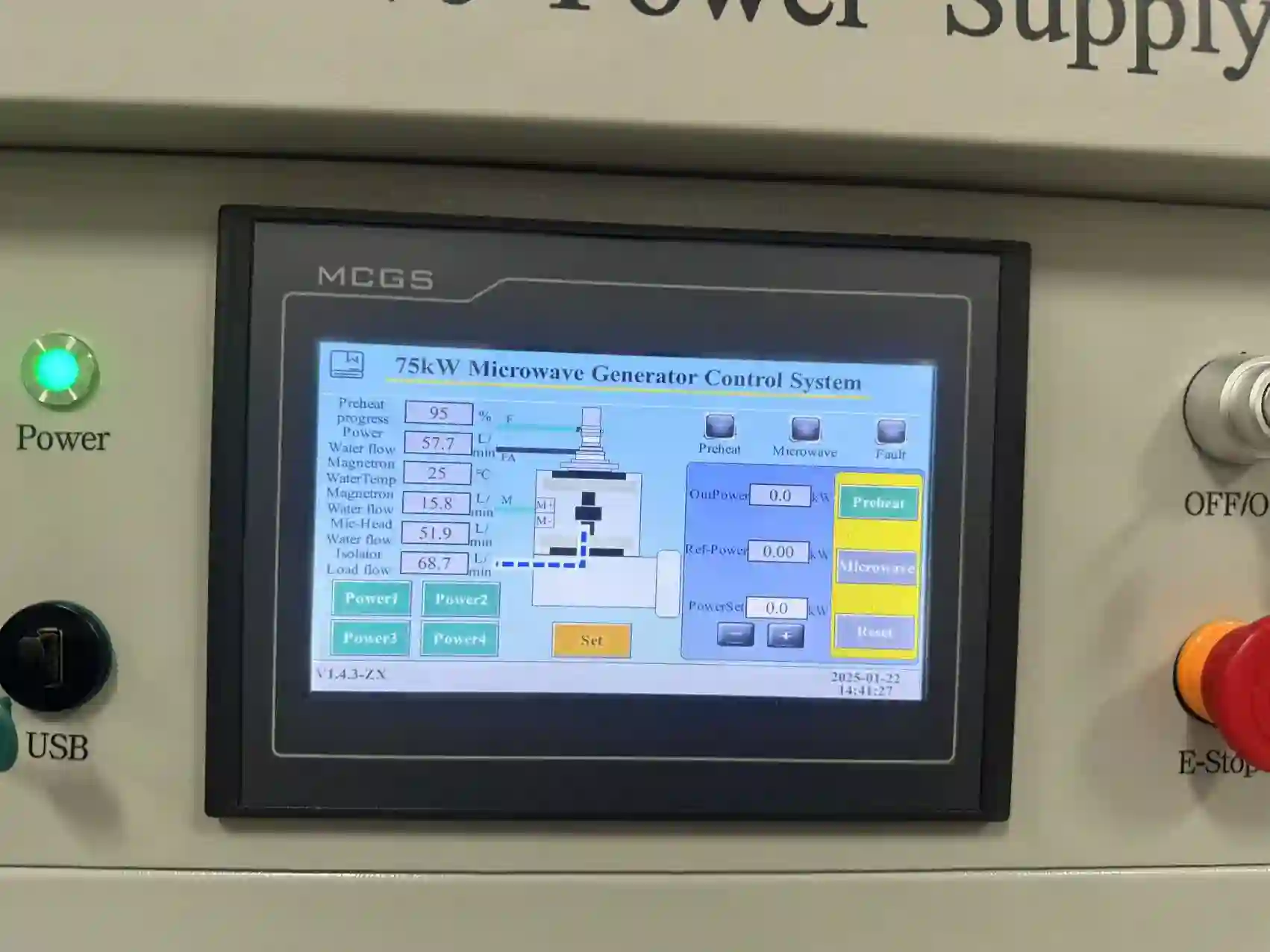
定义生成器和客户PLC需要交换的内容
所选模型和项目的精确显示参数、命令、通信细节和信号列表均已确认。.
启动、停止和电源设置
本地操作员控制系统可以根据模型配置提供发电机指令、功率调节、运行状态和故障信息。.
客户控制界面
在集成微波源之前,要明确所需通信方式、命令、监控数据和控制器之间的关系。.
运行状态
根据选定的控制方案,准备状态、运行状态、待机状态、报警状态和故障状态可以与客户设备进行协调。.
报警和故障信息
故障信息有助于操作人员识别导致正常运行受阻的电气、热能、冷却、射频或设备联动情况。.
前向/反射功率
如果所选的射频配置包含所需的监测组件,则可以添加前向和反射式微波功率监测功能。.
设备许可
发电机的操作可以与已商定的冷却、室温、RF 和设备条件相匹配,以便微波源在机器序列中正常运行。.
本地 HMI、发电机控制器和客户设备
Monitor the Conditions That Matter to High-Power Operation
Protection thresholds, shutdown actions and recovery logic remain specific to the selected generator configuration.
Water-Flow Conditions
Cooling-water conditions can form part of the generator permissive and protective logic.
温度条件
Temperature monitoring helps protect the microwave head and electrical power components.
电气保护
Electrical operating conditions and faults form part of the high-power generator protection strategy.
Arc Conditions
Arc-related protection can be included according to the selected generator and RF configuration.
Reflected-Power Management
Reflected microwave energy should be reviewed with the RF isolation, monitoring and equipment-load conditions.
安全锁
Generator operating permission should be coordinated with the agreed machine and process-equipment conditions.
Reflected Power Is a System Condition — Not Only a Generator Setting
Reflected microwave energy is affected by the load, chamber or applicator, coupling conditions and RF transmission path. Monitoring and protective logic should therefore be reviewed together with the complete microwave system.
Documented Functions on the 75 kW Configuration
Local HMI operation is documented for the 75 kW configuration.
RS485 communication is documented for this high-power configuration.
Generator status and fault information form part of the high-power control architecture.
Electrical, temperature, water-flow and arc-related protections are documented.
Communication registers, exact protection thresholds, response times and recovery logic are confirmed for the selected generator configuration.
Tell Us How the Generator Must Communicate with Your Machine
For a new OEM system or replacement project, provide the control relationship required between the microwave source and your equipment.
Prepare the Site for a High-Power 915 MHz Microwave Generator
High-power microwave integration requires the generator, cooling system, electrical supply and installation layout to be reviewed together. Before final model selection, confirm the available cooling capacity, site electrical conditions, equipment location and service access.
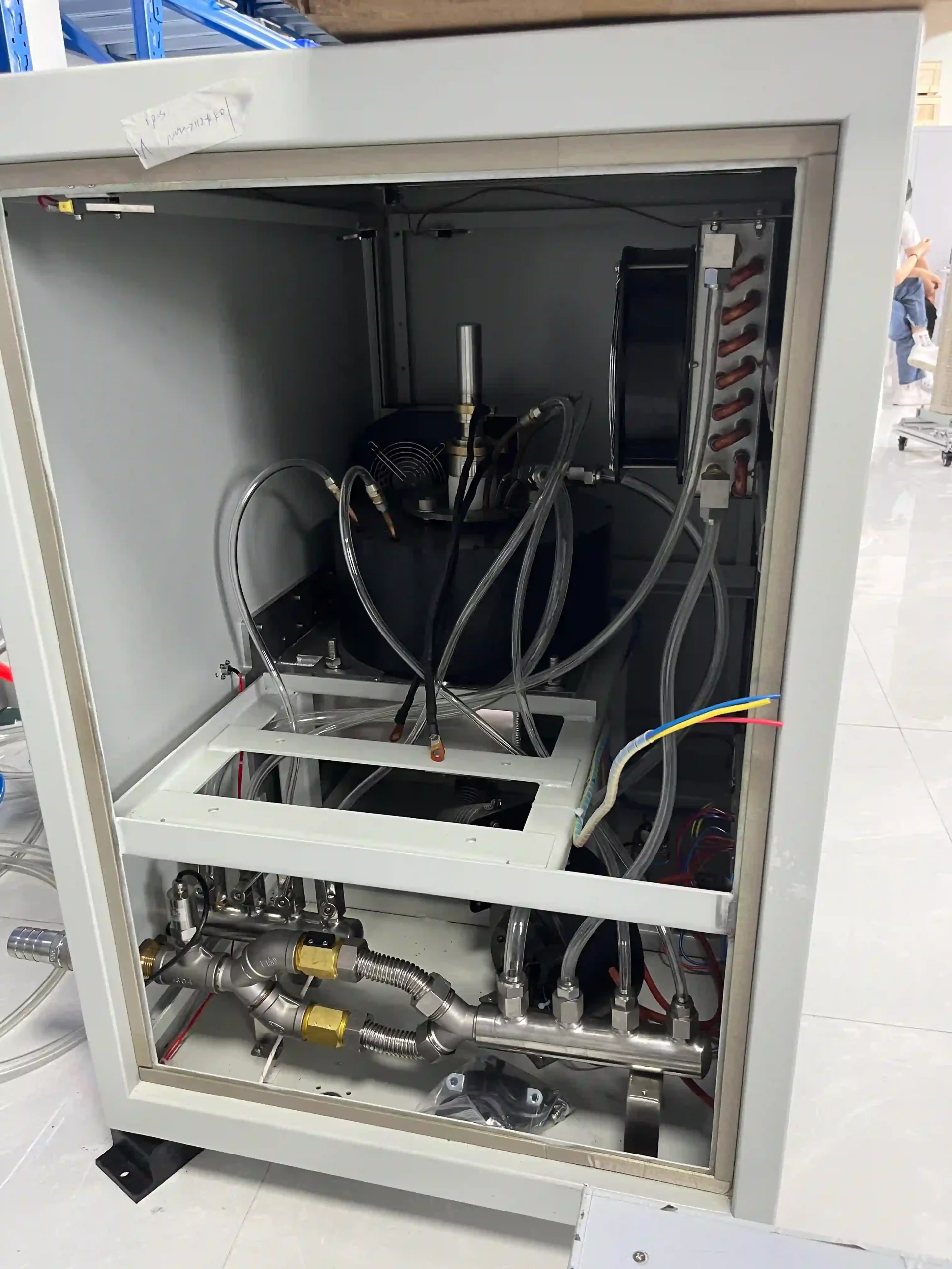
Confirm Cooling Capacity Before the Generator Is Finalized
Current published high-power 915 MHz configurations use water cooling. The cooling system must support the selected microwave generator under the actual operating and site conditions.
Required flow, pressure, temperature conditions and heat-rejection capacity should be confirmed for the selected model. A single cooling value should not be assumed across every 25–100 kW configuration.
Confirm whether the project uses a dedicated chiller or an available plant cooling-water system.
Cooling-water connections and operating conditions should match the selected generator configuration.
Cooling status can form part of the generator permissive and protective control logic.
Confirm the Available Electrical Supply Before Quotation
Input requirements vary by generator configuration. Provide actual site data instead of assuming one universal supply voltage for the complete 915 MHz series.
电压
Provide the available site input voltage so the electrical configuration can be reviewed.
Supply Frequency
Confirm the local electrical-supply frequency together with the available incoming power conditions.
Available Electrical Capacity
Verify that the facility can support the complete generator and required auxiliary-system electrical demand.
Upstream Protection
Incoming distribution and protective arrangements should be coordinated with the selected equipment.
接地
Confirm suitable protective grounding as part of the site electrical and equipment installation.
Power Connection Route
Review incoming cable routing and connection space together with cabinet location and installation access.
Plan the Cabinet, Microwave Head and RF Path as One Installation
The power cabinet, microwave head and process equipment may occupy different positions. Cable routing, cooling lines, microwave-head location, waveguide path and maintenance access should therefore be considered together.
电源和控制柜
Position the cabinet where electrical connection and service access can be maintained.
Cable & Control Routing
Confirm the connection route between the cabinet, microwave head and customer equipment.
微波头
Position the microwave head according to the RF output direction and mechanical arrangement.
Waveguide Path
Coordinate waveguide routing, RF components, supports and maintenance access.
工艺设备
Confirm the final chamber or applicator interface at the process side.
Eight Site Conditions to Confirm Before Final Configuration
Early confirmation of installation conditions reduces interface changes later in the equipment-integration process.
Provide the available cabinet and microwave-head installation area.
Allow access for inspection, connections and routine maintenance.
Confirm routing space, supports, transitions and process connection.
Define supply and return routing between cooling equipment and generator components.
Confirm the incoming supply and connection route to the power cabinet.
Provide relevant operating-environment information for the planned installation area.
Identify machine conditions that must permit or inhibit microwave operation.
Avoid layouts that restrict access to the cabinet, microwave head or RF components.
Utilities and RF Integration Must Be Reviewed Together
New OEM Systems and Retrofit Projects Need Different Checks
Design Utilities Around the Complete Microwave System
For a new machine, the generator, cooling system, electrical distribution and equipment layout can be coordinated before the final mechanical design is fixed.
- Target power and generator route
- Cabinet and microwave-head positions
- Chiller or plant cooling arrangement
- 站点输入功率
- 波导路径
- Control and interlock architecture
Compare Existing Utilities Before Selecting the Replacement
Existing electrical and cooling systems should not be assumed to suit a new microwave generator simply because nominal frequency and microwave power are similar.
- Existing generator nameplate
- Current input electrical data
- Existing cooling-system information
- Cabinet and head dimensions
- Current cable and pipe routes
- Existing control interfaces
Send Your Available Utilities and Installation Conditions
These basic site inputs help determine whether the initial generator configuration fits the electrical, cooling and mechanical conditions of the project.
Integrate a New 915 MHz Source or Review an Existing System for Replacement
High-power 915 MHz microwave projects generally follow one of two routes: integration into new OEM equipment or replacement of an existing microwave source. In both cases, generator selection should consider the electrical, RF, mechanical, control and cooling interfaces of the complete machine.
New OEM Microwave Generator Integration
For new equipment, the microwave source can be reviewed together with the process chamber or applicator, RF path, machine controls, cooling arrangement and available installation space.
Describe the material, plasma, chamber or applicator using microwave energy.
Define the required power class or initial engineering target.
Review waveguide, flange, coupling, RF components and routing.
Define local operation, communication, permissives and interlocks.
Confirm electrical supply, cooling capacity and installation conditions.
Clarify which generator and RF components are required within the quoted system.
Existing Generator Replacement & Retrofit
For an existing microwave system, begin with the installed generator and interface data. This helps identify which parts of the current machine may remain compatible and which interfaces may require modification.
Send the current model, nameplate and available technical information.
Confirm operating frequency, rated microwave power and input supply.
Provide cabinet dimensions, microwave-head dimensions and mounting information.
Send flange photographs, dimensions, orientation and existing RF-path information.
Identify remote commands, communication, status signals and machine interlocks.
Provide cooling information and explain the reason for replacement or upgrade.
Compare the Complete Interface — Not Frequency and kW Alone
Six interface groups help determine how much adaptation may be required when replacing an existing microwave source.
电气
Input voltage, frequency, available capacity, grounding, protection and connection method.
RF接口
Waveguide, flange geometry, output direction, RF components and reflected-power handling.
Mechanical
Cabinet size, microwave-head dimensions, mounting, orientation and service space.
控制
Local control, remote commands, communication, alarms and machine interlocks.
冷却
Cooling source, capacity, connections, pipe routing and operating conditions.
系统范围
Existing RF components, required adapters, customer-supplied equipment and project scope.
Photographs Can Start the First Retrofit Discussion
Complete engineering drawings are useful, but they are not necessary for the first review. Clear photographs of the current generator, nameplate, waveguide connection and installation arrangement can help identify the main interface questions.
- 频率
- Existing value
- 额定功率
- Existing value
- Input Supply
- Site data
- 型号
- Current source
From Requirement Review to Final Project Configuration
A structured review helps clarify the power route, interfaces and system scope before final equipment selection.
Requirement Intake
Application, country, power and project objective.
Power Route
Review the appropriate 915 MHz power configuration.
界面评论
Electrical, RF, mechanical, controls and cooling.
Define Scope
Generator, project RF components and customer interfaces.
配置
Confirm the proposed technical and commercial configuration.
Order Confirmation
Confirm agreed interfaces, testing and documentation.
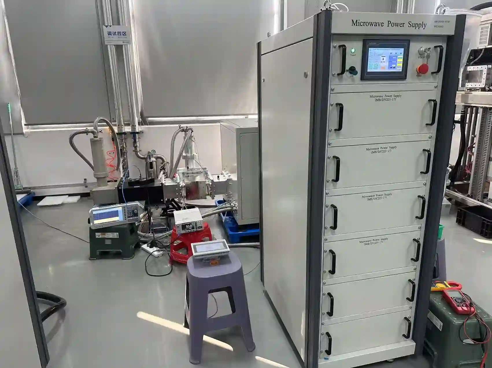
Define the Required Test Scope Before Delivery
Testing requirements should be coordinated with the selected generator configuration and project scope. This may include functional checks, operating-status verification and agreed interface or acceptance items.
For OEM projects, discussing the acceptance requirements before the final configuration is confirmed helps align the generator, controls, RF interfaces and project documentation.
Confirm agreed generator operating and control functions.
Review relevant RF, electrical, cooling and control interfaces.
Define required project-specific verification before delivery.
Confirm Technical Documents with the Selected Configuration
The required technical-document package depends on the selected model, project interfaces and agreed delivery scope. Confirm documentation requirements during the technical review.
Mechanical, electrical and RF information required for integration.
Required control and communication information according to configuration.
Testing and acceptance items defined by the confirmed project scope.
Documentation supplied according to the agreed equipment configuration.
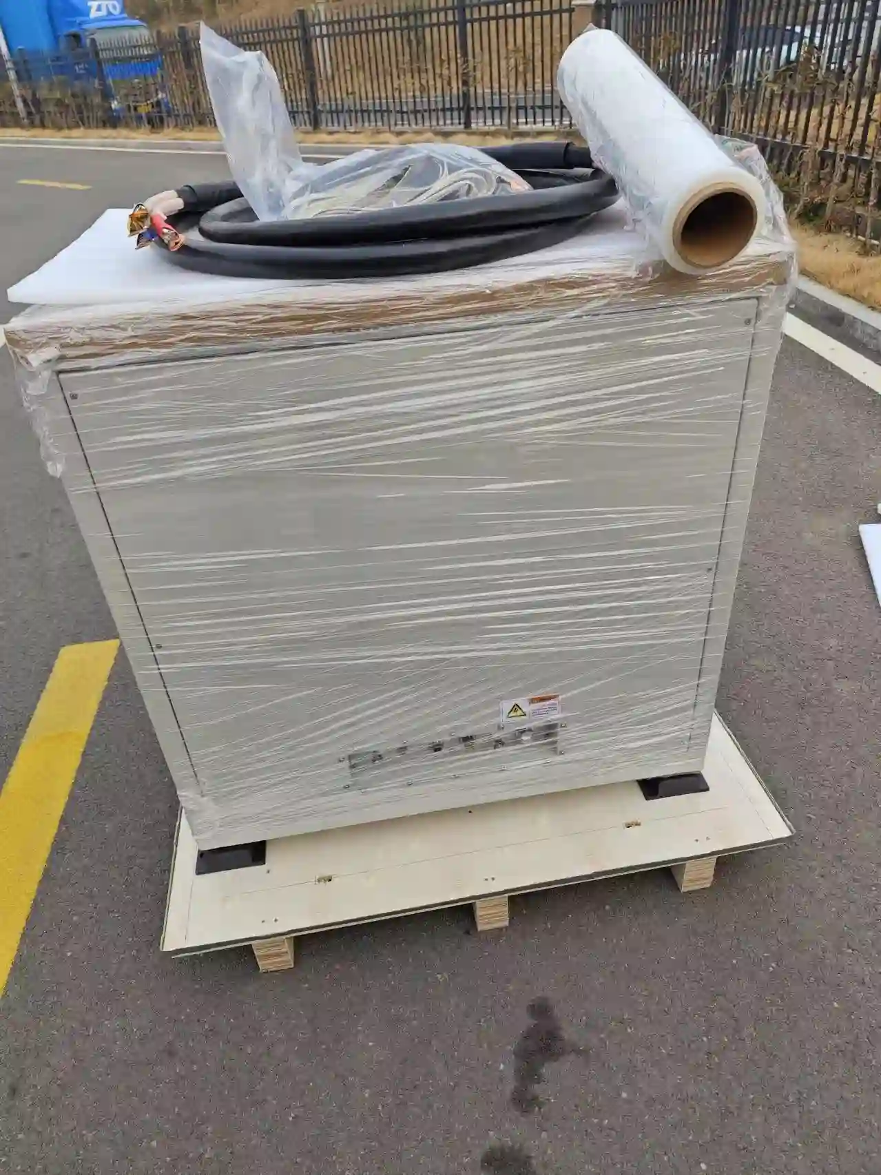
Prepare the Microwave Head and System Components for Delivery
High-power microwave projects can include separate cabinets, microwave heads, cables and RF components. Packaging and delivery preparation should follow the actual equipment configuration and agreed supply scope.
Before shipment, confirm the equipment list, interface documentation and installation information required by the receiving engineering team.
Send the Information Available for Your Project
You do not need to identify the exact generator model before contacting us. Start with your application requirements or the existing microwave-source information.
