High-Power Battery Emulation for R&D & Test Benches

Battery Emulator & Battery Simulator for High-Power DC Testing

Reproduce programmable battery and DC-bus conditions without relying on a physical battery pack for every test. The SDACME Battery Emulator combines bidirectional source and sink operation with programmable battery simulation for repeatable R&D, validation and automated test-bench workflows.

  • OCV-SOC Modelling
  • Internal Resistance
  • Dynamic SOC
  • Bidirectional Source & Sink
Tell Us What You Are Testing

Not sure about the required voltage, current or power yet? Start with the DUT and the test task.
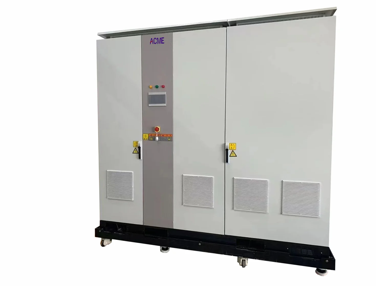
SDACME ACME800 high-power bidirectional DC platform for battery emulation
SDACME ACME800 Platform Programmable battery simulation · bidirectional DC source / sink
Repeatable Battery Conditions

Why Use a Battery Emulator Instead of Relying on a Real Battery?

A physical battery does not remain at the same electrical state throughout a test program. Voltage and state of charge change as energy moves in and out of the battery, making the same starting condition difficult to reproduce across repeated test runs. For R&D, validation and automated testing, those changing states often need to become controlled and repeatable test conditions.

With a Physical Battery

The Test State Keeps Changing

SOC and terminal voltage move as the battery is charged or discharged. Returning to the same electrical starting point may require additional charging, discharging or waiting between tests.

For Repeatable Validation

The Test State Needs to Be Defined

A programmable test system can reproduce selected battery states and operating points when they are needed, making repeated DUT comparisons easier to control.

01

Reproduce the Same Starting Condition

Repeat a defined battery state across development, regression and comparison tests instead of depending on the battery to return naturally to the same condition.

02

Reduce Waiting Between Test States

Move between required operating conditions without using a physical battery to create every SOC or voltage point in the test sequence.

03

Test More Than a Fixed DC Voltage

A regulated DC source can hold an electrical setpoint, but battery-related DUT testing may also require the source condition to change as the simulated battery state changes.

04

Build Repeatability Into Automated Validation

Defined electrical conditions can become part of a repeatable test workflow, helping the DUT encounter the intended operating points in the same sequence across multiple runs.

The Test Objective

Instead of asking the physical battery to create every test condition, define the required battery state in the test system and reproduce it when the DUT needs to see it.

Battery Emulator Basics

What Is a Battery Emulator?

A battery emulator, also called a battery simulator, is a programmable DC test source that reproduces the electrical behaviour a device under test would normally see from a battery. Instead of requiring the physical battery to create each test state, the emulator provides the required DC operating condition to the DUT.

Battery Emulation Test Relationship
Battery Model / Test Command
SOC OCV Profile Internal Resistance Test Sequence
Programmable Test Source

SDACME Battery Emulator

Converts the required battery model or test command into controlled DC operation for the DUT, with bidirectional source and sink capability.

DC Power Flow
Device Under Test

DUT

Inverter, charger, converter, PCS or another battery-connected power-electronic device that needs to see a controlled DC source.

The emulator reproduces the electrical condition the DUT would normally see from a battery while allowing power to flow in either direction when required by the test.

01

Supply Power to the DUT — and Absorb Power Returned by It

During one operating state, the DUT may draw energy from the simulated battery. During another, it may return energy toward the battery side. A bidirectional source/sink platform allows both power-flow directions to be handled within the same test system.

View the bidirectional DC platform →
02

Make Battery Behaviour Programmable

Battery Simulation functions can reproduce defined battery behaviour instead of treating the DUT as if it were connected only to a fixed DC voltage. Confirmed functions include OCV-SOC modelling, internal resistance, dynamic SOC and user-defined battery profiles.

Testing a Device — or Testing the Battery Itself?

A Battery Emulator is used when another DUT needs to see simulated battery conditions. If a physical battery cell, module or pack is itself the DUT and the objective is to charge, discharge or cycle that battery, the test task is different.

Not sure? Tell us what you are testing →
Programmable Battery Behavior

Reproduce How the DUT Sees the Battery as Its State Changes

Battery behaviour is not defined by voltage alone. As the simulated state changes, the electrical condition presented to the DUT can also change. SDACME Battery Simulation combines OCV-SOC modelling, internal-resistance simulation, dynamic SOC and custom battery curves to reproduce defined battery behaviour during the test.

From Battery State to the Electrical Condition Seen by the DUT
Battery State

OCV Changes With SOC

Conceptual relationship only. The actual profile depends on the battery data used for the test.

Programmable Model

Battery Simulation

OCV-SOC Modelling Define how open-circuit voltage changes with state of charge.
Internal Resistance Include battery resistance in the simulated electrical response.
Dynamic SOC Update the simulated battery state as the test progresses.
Custom Battery Curves Use custom curves or imported charge/discharge profiles.
Device Under Test

What the DUT Sees

  • Changing battery voltage
  • Source or sink current
  • Changing simulated SOC
  • Defined battery profile

The required behaviour depends on the DUT, operating range and validation objective.

01 / OCV-SOC

Reproduce Battery Voltage Across Different States of Charge

An OCV-SOC relationship allows the simulated open-circuit voltage to follow the selected state of charge instead of remaining at one fixed DC voltage. This gives the DUT a defined battery voltage profile across different test states.

02 / INTERNAL RESISTANCE

Include Internal Resistance in the Simulated Response

Battery terminal behaviour changes when current flows. Internal-resistance simulation allows the model to include that electrical characteristic rather than representing the battery as an ideal fixed-voltage source.

03 / DYNAMIC SOC

Let the Simulated SOC Change During the Test

Dynamic SOC allows the simulated battery state to change as energy moves through the test, so different operating points can be reproduced as part of a longer validation sequence.

04 / CUSTOM BATTERY CURVES

Use Battery Profiles Matched to the Test Requirement

Custom battery curves and charge/discharge profile import allow existing battery data to be brought into the test workflow. The applicable profile and configuration depend on the project data supplied.
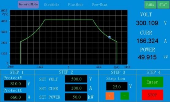
SDACME bidirectional DC power supply step programming HMI
Programmable Test Workflow

Build Changing Operating Conditions Into a Repeatable Sequence

Programmable voltage and current operating steps can be used as part of repeatable test workflows. This is useful when the DUT needs to encounter a defined sequence of electrical operating points rather than one static condition throughout the test.

Actual SDACME programming interface shown. This image illustrates programmable operating sequences and is not presented as a dedicated OCV-SOC battery-model screen.

Have a Different Battery Model or Test Profile?

The functions shown above are confirmed Battery Simulation capabilities, not a limit on the requirements you can bring to us. If the project uses another battery characteristic, an existing battery curve or a different test objective, provide the available profile and DUT operating conditions for review.

Discuss a Battery Simulation Requirement →
Bidirectional Power Flow

Source Power to the DUT — and Absorb Power Returned by It

A battery-connected DUT may not exchange power in only one direction. During one operating state it can draw energy from the battery side; during another it can return energy toward the battery. The SDACME Battery Emulator supports bidirectional source and sink operation so both conditions can be reproduced within the same DC test platform.

How Power Moves Through the Test System
Source Mode
Facility Side AC Supply
AC Power
Battery Simulation SDACME Battery Emulator Source operation
DC Power
Device Under Test DUT Draws power
Sink / Regeneration Mode
Facility Side AC Supply Receives regenerated energy
Regenerated Energy
Battery Simulation SDACME Battery Emulator Sink operation
Returned DC Power
Device Under Test DUT Returns power
01

Source Mode

When the DUT draws energy, the Battery Emulator operates as a DC source and reproduces the required battery-side operating condition for the test.

02

Sink Mode

When power flows back from the DUT, the same platform can absorb that returned DC energy instead of requiring a separate electronic load for the power-flow direction.

03

Regenerative Operation

Energy absorbed during sink operation can be converted back toward the AC supply rather than being handled only as dissipated heat. This is particularly relevant in repeated high-power test operation.

Does Your DUT Use Both Power-Flow Directions?

Not every test uses source and sink operation in the same way. Some DUTs mainly draw power, while others return significant energy during specific operating states. The required configuration should therefore be selected around the actual DC power flow, continuous operating level and test sequence.

Describe your DUT power flow →
Common Battery-Connected DUTs

What Can You Test With a Battery Emulator?

If the DUT normally connects to a battery pack or battery-side DC bus, battery emulation can provide controlled DC operating conditions without requiring the physical battery to create every test state. The required configuration depends on what the DUT does with that power: whether it draws energy, returns energy, or operates in both directions.

01

Inverter & Electric Drive Testing

Reproduce the battery-side DC supply seen by traction inverters, motor controllers and electric-drive systems during development and validation. Bidirectional operation is useful where the DUT can both draw power and return energy during different operating states.

Typical Test Question How does the drive behave as the simulated battery state and DC operating point change?
02

OBC & DC-DC Converter Testing

For on-board chargers and DC-DC converters that interact with a battery-side DC bus, the required battery-emulation configuration can be evaluated from the DUT voltage range, power direction and test sequence.

Typical Test Question What DC conditions must the converter see across its intended battery operating range?
03

EV Charger & EVSE DC-Side Testing

On the DC power side of EV charging equipment, a Battery Emulator can reproduce the battery load seen by the charger and absorb the charging power under controlled test conditions.

Typical Test Question How does the charger respond as the simulated battery voltage and charging condition change?
04

PCS & Energy Storage Converter Testing

Reproduce the battery-side DC source and sink conditions required by a power conversion system or energy-storage converter, including operating states where energy moves toward or away from the simulated battery.

Typical Test Question Can the PCS be validated across different battery-side voltage, power and bidirectional operating conditions?
Beyond These Examples

Testing Something Else on a Battery or DC Bus?

The applications above are common DUT examples, not an application limit. Other battery-connected power electronics can be reviewed from the DUT function, required DC operating range, expected power flow and the battery behaviour that needs to be reproduced.

Industrial DC Equipment Electrified Propulsion Stationary Energy Systems DC Bus Test Systems Other Power Electronics

What Does Your DUT Need From the Battery Side?

Start with the equipment you are testing and the behaviour it needs to see from the battery or DC bus. Voltage, current and power values are useful if available, but they do not need to be finalized before the first discussion.

Tell us what you are testing →
Specifications & Selection

Match the Battery Emulator to Your DUT Operating Range

Battery Emulator selection starts with the electrical conditions the DUT needs to see, not with a model number alone. DC voltage range, current, continuous power, power-flow direction and the actual test sequence should be considered together when selecting the configuration.

01 / VOLTAGE

What DC Voltage Range Does the DUT Need?

Start with the minimum and maximum DC voltage the DUT must see during the test, rather than nominal battery voltage alone.

02 / CURRENT

How Much Current Flows in Each Direction?

Define the expected source current and, where applicable, the current returned from the DUT during sink or regenerative operation.

03 / POWER

What Is the Continuous Test Power?

Continuous power should be defined first. If the DUT also has higher short-duration operating points, include the approximate peak level and duration.

04 / DUTY CYCLE

How Does the Test Move Between Operating Points?

A test with one steady operating point can require a different configuration from a repeated high-current or rapidly changing validation sequence.

Voltage, Current and Power Must Be Checked Together

Maximum voltage, maximum current and maximum power should not be assumed to be simultaneously available across the entire operating range. The DUT operating points need to remain within the selected configuration's voltage, current and continuous-power envelope.

Standard Model Matrix

The models below provide standard selection points for the current ACME800 series. The final choice still depends on the actual voltage, current and power operating points required by the DUT.

型号DC Voltage RangeRated Current额定功率
ACME800-10024–800 VDC±100 A60 kW
ACME800-20024–800 VDC±200 A60 kW
ACME800-30024–800 VDC±300 A90 kW
ACME800-50024–800 VDC±500 A160 kW
ACME800-60024–800 VDC±600 A250 kW
ACME800-80024–800 VDC±800 A350 kW

These standard models are selection starting points. Project requirements outside this matrix should be reviewed from the required operating envelope.

Beyond the Standard 800V Model Matrix

Need Higher Voltage or Higher Power?

The SDACME bidirectional DC platform is confirmed for configurations up to 1000V and 500kW. The exact voltage, current and power combination should be selected around the DUT operating envelope. Requirements beyond the confirmed series range can also be submitted for project review.

1000V / 500kW Confirmed series capability

Current Public Specification Baseline

Operating Modes CV / CC / CP
Standard DC Range 24–800 VDC
Standard Rated Current Up to ±800 A*
Standard Rated Power Up to 350 kW*
Extended Series Capability Up to 1000 V / 500 kW
Voltage Accuracy 0.1% FS
Current Accuracy 0.1% FS
Power Accuracy 0.2% FS
Voltage Ripple 0.2% FS
暂时的恢复 5 ms

* Model dependent. Final performance and operating limits should be confirmed against the selected configuration.

Match the Emulator to the Available AC Supply

Include the facility voltage and frequency in the RFQ so the AC-side configuration can be matched to the installation. The standard input baseline is 380VAC ±10%, 50Hz. Common overseas voltage configurations are also supported, and 60Hz operation is available for applicable projects.

Standard Input 380VAC ±10% · 50Hz
Overseas Grid Options 400 / 415 / 440 / 480VAC configurations; 60Hz supported

Have the DUT Specification but Not the Battery Emulator Model?

You do not need to select an ACME model first. Send the DUT specification or the operating information you already know and the configuration can be narrowed from there.

DUT / equipment being tested
Minimum & maximum DC voltage
Typical & maximum current
Continuous power
Source / sink / both directions
Peak level & duration if applicable
Battery profile / simulation task
Available AC supply

Do not have every value yet? Start with the DUT and an approximate voltage or power range. Complete engineering data is not required for the first discussion.

Send Your DUT Requirements →
Communication & Automation

Control the Battery Emulator From Your Test Bench

Battery emulation is often one part of a larger validation workflow. The SDACME Battery Emulator can be integrated with a host computer or automated test bench for remote operating-point control, equipment monitoring and coordinated test operation.
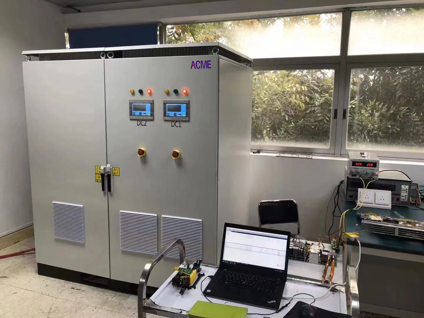
SDACME bidirectional DC test platform integrated with a host computer test bench
Test-Bench Integration

Connect the Power Platform to the Existing Test Workflow

The Battery Emulator does not need to operate only as a standalone front-panel instrument. Remote communication allows the power stage to participate in a larger test system controlled by a host computer, industrial controller or automation platform.

Integration should start with what the test controller needs to command and what operating information it needs to receive during the sequence.

01 / REMOTE CONTROL

Command Voltage, Current and Power Remotely

A connected host system can set target voltage, current or power values as part of the test workflow. This allows the Battery Emulator operating point to change with the required DUT test condition instead of relying on manual front-panel adjustment for every step.

02 / MONITORING

Read Operating Status and Fault Information

Remote integration can return equipment status and fault information to the supervisory test system. Remote start, stop and reset functions can also be incorporated into the test workflow where required.

Confirmed Communication Interfaces

Connect Through the Interface That Fits the Test Bench

Current confirmed interfaces include RS485, CAN, Ethernet and USB. The final communication method should be selected around the existing controller, DUT and automation architecture.
RS485
CAN
Ethernet
USB
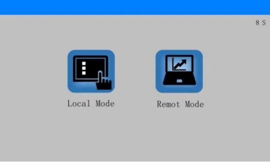
SDACME bidirectional DC power supply local and remote control mode HMI
Local / Remote Operation

Move Control From the Front Panel to the Test System

Local and remote operating modes allow the equipment to be used manually during setup or placed under external control as part of the test bench.

SDACME bidirectional DC power supply step programming HMI
Programmable Sequence

Build Changing Operating Points Into the Test Process

Programmable operating steps support repeatable sequences where voltage or current conditions need to change during DUT validation.

Existing Automation Architecture

Already Have a PLC, Host PC or Test-Control System?

Start with the architecture you already use. If the project requires a different communication method, controller or supervisory workflow, provide the existing interface requirements and the control tasks the Battery Emulator needs to perform. The applicable integration scope can then be reviewed with the selected electrical configuration.

Describe Your Test Bench →
Choose by the DUT

Battery Emulator vs Battery Cycler: Which Test Task Do You Have?

The simplest way to distinguish the two is to identify the device under test. A Battery Emulator reproduces the battery for another DUT. A Battery Cycler applies controlled charge and discharge conditions to a physical battery that is itself being tested.

Battery Emulator

Another Device Is the DUT

Use battery emulation when an inverter, charger, converter, PCS or another power-electronic DUT needs to operate as if it were connected to a battery.

Simulated Battery Battery Model Defined battery condition
Test Source Battery Emulator
Device Under Test Real DUT Inverter · Charger · Converter · PCS · Other
Main Question What electrical battery condition does the DUT need to see?
Battery Cycler

The Physical Battery Is the DUT

Use battery cycling when the purpose of the test is to charge, discharge or characterize an actual battery cell, module or pack.

Test Equipment Battery Test / Cycling System
Device Under Test Real Battery Cell · Module · Pack
Main Question How does the physical battery perform during charge and discharge?
Decision PointBattery EmulatorBattery Cycler
What is being simulated?The batteryNo battery replacement — a real battery is connected
What is the DUT?A battery-connected deviceThe battery cell, module or pack
Main test objectiveReproduce battery conditions for another DUTCharge, discharge and test the physical battery
Typical starting informationDUT, DC range, power flow and battery profileBattery type, voltage/current range and battery test task

Still Not Sure? Start With the DUT.

You do not need to know the correct product name before contacting us. Tell us what equipment is physically connected to the test system and what you want to verify. We can use that information to identify whether the requirement is battery emulation, physical battery testing or a related DC test task.

Tell Us What You Are Testing →
Battery Emulator FAQ

Battery Emulator Questions Engineers Ask Before Selection

Start with the test task, the DUT and the DC operating conditions that need to be reproduced. The answers below cover the main questions used to determine whether battery emulation fits the application and what information is needed for selection.

What is a battery emulator?

A battery emulator is a programmable DC test source that reproduces the electrical conditions a DUT would normally see from a battery.

Instead of using a physical battery pack to create every test state, the emulator can provide defined battery-related DC conditions for development, validation and repeatable test workflows. Depending on the DUT, power may need to flow from the emulator to the DUT, from the DUT back to the emulator, or in both directions.

Is a battery emulator the same as a battery simulator?

In high-power DC testing, “battery emulator” and “battery simulator” are commonly used for the same basic test function.

Both terms describe equipment used to reproduce battery-like electrical conditions for another device under test. The more important selection question is not the terminology, but the required voltage, current, power direction, battery model and test objective.

Can a battery emulator replace a real battery during testing?

A battery emulator can replace the physical battery for many electrical DUT tests where controlled and repeatable battery conditions are needed.

It is particularly useful when the goal is to reproduce selected operating states repeatedly without charging or discharging a real battery to reach each starting condition. Whether it can replace the physical battery for a particular test depends on what battery behaviour the DUT must see and what the validation task is intended to verify.

What battery behaviour can the SDACME Battery Emulator simulate?

Confirmed Battery Simulation functions include OCV-SOC modelling, internal-resistance simulation, dynamic SOC, custom battery curves and charge/discharge profile import.

These functions allow the electrical condition presented to the DUT to change with the defined simulated battery state instead of behaving only like a fixed DC voltage source. If the project uses another battery characteristic or existing test profile, provide the available data so the required simulation scope can be reviewed.

Why does a battery emulator need both source and sink operation?

Because some DUTs draw power from the simulated battery during one operating state and return power toward it during another.

In source mode, the Battery Emulator supplies DC power to the DUT. In sink mode, it absorbs power returned from the DUT. SDACME's bidirectional platform also supports regenerative operation, allowing absorbed energy to be returned toward the AC supply rather than being handled only as dissipated heat.

How do I select the required battery emulator voltage, current and power?

Select the system from the DUT's complete operating envelope, not from one maximum number alone.

Provide the minimum and maximum DC voltage, expected current in each power-flow direction, continuous power, and any higher short-duration operating points. Peak duration and duty cycle are also important where the DUT repeatedly moves through high-power states.

Maximum voltage, maximum current and maximum power should not be assumed to occur simultaneously across the full operating range.

Can SDACME review battery emulator requirements outside the standard configurations?

Yes. The standard ACME800 matrix is a selection starting point, not the only type of requirement that can be submitted.

Current confirmed bidirectional DC configurations extend up to 1000V and 500kW. Requirements outside the standard 24–800V model matrix, or projects with a different voltage, current, power, battery profile or integration requirement, can be reviewed from the actual DUT and test conditions.

If the final electrical specification is not yet complete, start with the DUT, the approximate DC range and what you need the test system to reproduce.

Have a Test Question That Is Not Covered Here?

Send the DUT, the test objective and whatever electrical information is already available. You do not need to translate the requirement into an ACME model number before contacting us.

Ask About Your Application →
Battery Emulator Project Review

Tell Us What You Are Testing

Send us the available DUT, DC operating range and test information. SDACME can review the required Battery Emulator configuration, battery simulation functions, bidirectional power requirements and test-bench integration needs for the proposed application.

Start with the DUT — not with an ACME model number. A complete electrical specification is not required for the first discussion. Approximate values and existing DUT data are enough to begin reviewing the test requirement.
Information to Provide

Basic Data for Battery Emulator Selection

Provide as much information as currently available. Missing items can be clarified during the technical review.

  • 01
    Device Under Test Inverter, charger, converter, PCS or other battery-connected equipment being tested.
  • 02
    DC Operating Range Minimum and maximum voltage plus the expected current and continuous power range.
  • 03
    Power-Flow Direction Whether the DUT draws power, returns power, or operates in both directions.
  • 04
    Battery Simulation Requirement Battery profile, OCV-SOC behaviour, internal resistance, dynamic SOC or other available test information.
  • 05
    Peak & Test Sequence Peak operating point and duration, duty cycle, repeated steps or other changing test conditions.
  • 06
    AC Supply & Test-Bench Integration Available facility AC supply and any communication, host-control or automation requirements already known.
Project-specific engineering: final voltage, current, power, battery simulation functions, communication method and system configuration are defined according to the agreed DUT conditions and technical scope.
SDACME Battery Emulator Systems