Industrial Microwave Generator Safety Standards & Compliance Guide
Industrial microwave generator safety standards cover more than the microwave source itself. Safety, RF containment, EMC, machine interlocks, verification and destination-market requirements need to be evaluated across the actual equipment architecture. Requirements depend on the selected generator, operating frequency, RF system, installation and final market.
Safety & Compliance Scope
Safety and Compliance Must Be Evaluated at Equipment Level
An industrial microwave generator operates as part of a larger electrical and RF system. The compliance plan therefore needs to consider both the generator itself and the way it is integrated into the final machine, installation and destination market.
Compliance Scope Expands with the Supply Boundary
Define exactly what is being supplied before selecting standards, tests and documentation requirements.
Microwave Generator
Generator-level electrical, control and protection functions.
Microwave Subsystem
Generator integrated with the microwave transmission path.
Complete Machine
Microwave subsystem coordinated with the machine safety architecture.
Installation & Market
Final operating environment and destination-market requirements.
Four Questions to Define Before Compliance Planning
Establishing these inputs early helps align generator selection, machine integration, testing and documentation with the actual project.
What Equipment Is Being Evaluated?
First define the physical and contractual boundary of the equipment being reviewed.
- Generator only
- Microwave generator subsystem
- Generator with microwave head and waveguide
- OEM machine integration
- Complete processing equipment
Where Will the Equipment Be Installed?
Destination country and installation environment influence the compliance route and technical requirements.
- Frequency use
- RF emission requirements
- Market-access procedures
- Technical documentation
- Installation and occupational-safety requirements
What Safety Functions Are Required?
The complete machine risk assessment should identify the conditions that permit or inhibit microwave operation.
- Emergency stop
- Guard or door interlocking
- Microwave enable / inhibit
- Cooling-related interlocks
- Fault shutdown and safe restart
What Verification Is Required?
Define the inspections, measurements and records needed for the agreed equipment scope.
- Electrical inspection and functional checks
- Safety interlock verification
- Microwave leakage measurement
- RF / EMC testing where applicable
- FAT, SAT and project documentation
Generator-level requirements and complete-machine requirements are related, but they are not necessarily identical. Define the equipment boundary first, then establish the applicable safety, EMC, RF and market-compliance plan.
Key Standards and Regulatory Topics for Industrial Microwave Equipment
Industrial microwave compliance is normally built from several technical and regulatory layers. Microwave-specific safety, EMC emissions, machine safety and destination-market requirements address different parts of the equipment assessment.
One Microwave System — Multiple Compliance Layers
The standards relevant to a project depend on the equipment boundary, machine architecture and destination market.
The applicable compliance route is built around the actual product. Generator design, RF transmission, machine guarding, control architecture, EMC performance and market requirements need to be evaluated together.
What Each Standard Contributes
Standards should be used according to their technical scope. Their roles overlap at system level, but they should not be treated as interchangeable certificates.
IEC 60519-1 & IEC 60519-6
SafetyIEC 60519-1 establishes the general safety framework for industrial electroheating and electromagnetic processing. IEC 60519-6 adds particular requirements for high-frequency dielectric and microwave heating and processing equipment, including microwave generators within its scope.
CISPR 11
EMCCISPR 11 is an important EMC reference for industrial, scientific and medical equipment. It addresses RF disturbance emissions and provides the framework for applicable limits and measurement methods.
FCC Part 18
U.S. MarketIndustrial microwave equipment intended for the United States should be reviewed against the applicable FCC Part 18 requirements. Equipment classification, frequency use, emissions and the applicable authorization route form part of that review.
ISO 13849-1 / IEC 62061
Functional SafetyThese standards can be relevant when designing and validating safety-related machine control functions. The required performance is determined from the defined safety function and complete machine risk assessment.
A Standard Is Not Automatically a Product Certificate
Standards provide technical requirements, assessment methods and engineering frameworks. The final conformity claim depends on the actual product, applicable market route and supporting verification evidence.
Define the Compliance Route Before Testing
- Define the equipment and supply boundary.
- Identify the destination country or region.
- Identify applicable safety and EMC requirements.
- Define machine safety functions where required.
- Establish test methods and acceptance criteria.
- Confirm required technical documentation.
No single standard defines the complete compliance status of every industrial microwave installation. Build the standards and verification plan around the actual generator, RF system, complete machine and destination market.
2450 MHz and 915 MHz Require Different Regulatory Review
Operating frequency affects more than microwave-system design. It can also affect spectrum use, interference control, equipment evaluation and destination-market planning. Frequency should therefore be reviewed from both microwave-engineering and regulatory perspectives.
Widely Used for Industrial Microwave Systems
2450 MHz is widely used for industrial microwave generation and processing. Regulatory planning should still consider the complete equipment and the market where it will be installed or supplied.
- Confirm destination-country requirements.
- Review applicable equipment classification.
- Control emissions outside the intended operating band.
- Coordinate shielding and microwave containment.
- Define final RF leakage verification.
- Review local installation requirements.
Destination Market Must Be Confirmed Early
915 MHz should not be treated as having identical regulatory availability worldwide. National spectrum rules and equipment requirements need to be checked for the intended destination market.
- Confirm destination country or region.
- Confirm the permitted frequency range.
- Review the intended equipment category and use.
- Evaluate applicable RF emission requirements.
- Consider the local interference environment.
- Identify required authorization or documentation.
ISM designation and market compliance are related, but they are not the same decision. The project still needs to consider equipment classification, emissions, installation, documentation and destination-country rules.
Frequency Selection Is Both an RF and Regulatory Decision
A suitable operating frequency needs to work technically with the process while also fitting the intended equipment and market. These two evaluations should be performed together.
Microwave Engineering
Select the frequency as part of the complete microwave power-delivery and process architecture.
- Required microwave power
- Process load and material behavior
- Applicator or chamber design
- Waveguide architecture
- Matching and reflected-power management
- Process uniformity and operating strategy
Regulatory Engineering
Confirm that the selected frequency and equipment configuration fit the destination-market compliance plan.
- Destination country or region
- Permitted spectrum use
- Equipment classification
- RF emission requirements
- Applicable authorization route
- Required technical documentation
Define These Inputs Before Final Frequency Selection
Early confirmation reduces the risk of changing generator, waveguide or compliance planning after the equipment design has already progressed.
Destination Market
Country or region where the final equipment will be placed, installed and operated.
Power Requirement
Required microwave output and expected operating range for the process.
RF System
Microwave head, waveguide, applicator, chamber and process-load configuration.
Compliance Scope
Generator, subsystem or complete-machine requirements and required documentation.
Confirm the Destination Country Before RF Design Is Frozen
For a 915 MHz industrial microwave project, provide the destination market during the initial engineering review. Frequency availability, RF emission requirements and the applicable compliance route can then be considered together with microwave power, waveguide and applicator selection.
Control Microwave Energy from Source to Load
Microwave safety depends on the complete RF power path, including the generator, microwave head, waveguide, interfaces, applicator or chamber and accessible openings. Safe equipment combines RF containment, access control, shielding and final verification.
Safety Must Follow the Complete Microwave Transmission Path
Each interface between the microwave source and process load can influence RF containment, access safety and final leakage performance.
RF Containment
Maintain an engineered metallic containment path around the microwave-energy system.
Waveguide Joints
Correct flange alignment, connections and assembly are important to RF containment.
Protected Access
Coordinate doors, covers and service access with the equipment guarding and interlock strategy.
Shielding & Filtering
Manage RF paths around electrical, signal and structural penetrations.
Leakage Verification
Measure accessible RF containment boundaries on the assembled equipment.
Final RF safety is a system-level result. Generator design alone cannot replace correct waveguide assembly, chamber shielding, access control and final microwave-leakage verification.
Build RF Safety into the Equipment Architecture
Mechanical construction, RF engineering and machine controls should support the same containment strategy rather than being treated as independent design tasks.
Microwave Containment
The generator, transmission components and process chamber form a complete RF containment system. Construction details at joints and openings influence final leakage performance.
- Waveguide flanges and connections
- Applicator and chamber interfaces
- Service openings and penetrations
- Doors and removable covers
Shielding
Metallic shielding is used to limit unintended RF energy around the microwave system. Its effectiveness depends on the installed enclosure, joints, openings and interfaces.
- Cabinet and chamber structure
- RF-sensitive access points
- Observation or process openings
- Mechanical joints and interfaces
Filtering & Penetrations
Electrical power, signals, sensors and utilities create necessary penetrations through the equipment enclosure. Their implementation should support both RF containment and EMC performance.
- Power and signal interfaces
- Cable routing
- Filtering where applicable
- Grounding and bonding coordination
Guards & Access Control
Access to areas where microwave energy may be present should be coordinated with the complete machine guarding and interlock strategy.
- Process doors
- Maintenance access
- Service panels
- Guard and interlock interfaces
Verify Accessible RF Boundaries on the Assembled Equipment
Microwave leakage measurement should use the applicable test method and acceptance criteria for the equipment and market. Measurements are most meaningful after the RF system, chamber, guards and interfaces have been assembled.
Consider Where People Are Located Around the Equipment
The final installation should consider applicable occupational RF exposure requirements together with normal operator positions, maintenance access and other occupied areas around the microwave equipment. Final exposure assessment belongs to the complete installed-system safety plan.
Integrate the Microwave Source into the Equipment Safety Architecture
An industrial microwave generator should operate only when the required machine conditions are satisfied. The generator's control, monitoring and protection interfaces therefore need to be coordinated with guarding, emergency-stop functions, utilities and the final equipment control architecture.
Microwave Operation Depends on Defined Machine Conditions
The complete equipment design establishes when microwave generation is permitted, when it must be inhibited and how the machine responds to abnormal operating conditions.
Access Condition
Required guards, doors or protected access points are in the defined operating condition.
Cooling Condition
Required cooling conditions are available for the selected generator and RF equipment.
Control Permission
The host machine or control system provides the required microwave enable condition.
No Active Fault
Conditions requiring microwave inhibition or shutdown have been evaluated by the control system.
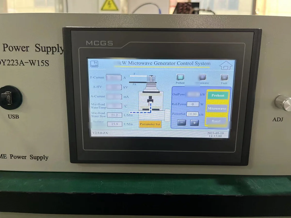
15 kW Microwave Generator HMI Control Interface
Generator-level operating status and control functions support equipment integration. The final machine safety architecture is defined around the complete system and required safety functions.
Key Machine-Safety Functions to Coordinate
The exact implementation depends on the final machine risk assessment, operating sequence and equipment architecture. These functions should be defined during system integration rather than added after installation.
Emergency Stop
The machine emergency-stop strategy should bring microwave operation to the defined safe condition as part of the complete equipment stopping architecture.
Guard Interlock
Doors, covers or other guards protecting areas where microwave energy may be present can be coordinated with the microwave operating permission.
Microwave Enable / Inhibit
The equipment control system should establish the conditions under which microwave generation is permitted and the conditions that require microwave power to remain inhibited.
Cooling Conditions
Where microwave generator or microwave-head operation depends on cooling, relevant cooling conditions can be incorporated into the equipment interlock strategy.
Fault Handling
Equipment faults should produce the defined machine response and provide appropriate status information to the operator or host control system.
Restart Strategy
Restart behavior following an interruption, safety demand or equipment fault should be defined from the machine risk assessment and operating sequence.
Coordinate Electrical Protection with the Installation
Industrial microwave systems combine electrical power, control circuits and microwave-generation hardware. Electrical protection should therefore be evaluated against the selected equipment and complete installation.
Generator Interfaces and Machine Safety Work Together
A microwave generator provides part of the control and protection architecture. The final machine integrates those interfaces with the rest of the equipment.
Control, Status & Protection Interfaces
The microwave subsystem provides defined operating, monitoring and protection functions that can be coordinated with the host machine during OEM integration.
Guards, E-Stop, Utilities & Safety Architecture
The equipment integrator coordinates generator interfaces with guarding, emergency stop, utilities, process equipment and the defined machine safety functions.
A generator interlock input is one element of a larger machine-control architecture. The required safety response is defined by the hazard, complete safety function and machine risk assessment.
PL and SIL Apply to Defined Safety Functions
Performance Level and Safety Integrity Level are used when engineering defined safety-related control functions. They should not be treated as generic ratings automatically assigned to a microwave generator simply because the generator provides an interlock or enable input.
Start with the Safety Function — Not the Generator Label
A safety-related function is defined from the hazard, required machine response and complete control architecture. Sensor inputs, logic, output elements and the microwave source may all form part of the same safety chain.
Build Functional Safety from the Risk Assessment
The engineering process begins with the machine and the hazard. Only after the required safety function has been defined should the required performance and control architecture be selected.
Identify the Hazard
Identify hazardous situations associated with microwave energy, electrical energy, machine access, moving equipment, utilities or other process-specific hazards.
Risk AssessmentDefine the Safety Function
Define what the equipment must do when a safety condition occurs, such as preventing or removing microwave generation.
Required ResponseDetermine Required Performance
Determine the required performance of the defined safety function using the applicable machinery-safety methodology.
PLr / SILDesign the Safety Chain
Coordinate sensing, safety-related control logic, output elements and the microwave source as one complete function.
ArchitectureVerify & Validate
Confirm that the implemented safety function achieves its defined response and required performance in the complete machine.
ValidationEvaluate the Complete Safety-Related Control Chain
The exact components and architecture depend on the machine design and required safety function.
Sensor / Safety Device
Guard switch, emergency-stop device or other sensing element used by the defined safety function.
Safety-Related Control Logic
Evaluates the safety demand and generates the required control response.
Final Switching / Control Element
Executes the required output action within the safety-related machine-control architecture.
Microwave Source
Microwave generation is enabled, inhibited or otherwise controlled according to the defined machine response.
The complete implemented function must be evaluated. Validation is not limited to confirming that a single generator interlock input changes state.
ISO 13849-1 and IEC 62061 Address Safety-Related Control Functions
Both frameworks can be relevant to machinery functional safety. The appropriate methodology depends on the complete equipment, customer specification and applicable conformity strategy.
ISO 13849-1
Performance Level Approach
ISO 13849-1 provides a methodology for designing and integrating safety-related parts of control systems that perform defined machine safety functions.
- Begin with the defined machine safety function.
- Determine the required performance for that function.
- Evaluate the complete safety-related control architecture.
- Verify and validate the implemented function.
IEC 62061
SIL-Based Machinery Approach
IEC 62061 provides requirements and recommendations for the design, integration and validation of safety-related control systems used to carry out safety functions on machinery.
- Define the required machine safety function.
- Establish the required integrity for that function.
- Design the safety-related control system.
- Validate the complete implemented function.
“The Generator Has an Interlock, Therefore the Machine Is PL d / SIL 2”
An interlock interface alone does not define the performance of the complete machine safety function. The sensing device, control logic, output architecture and implemented response also need to be considered.
Define the Safety Function, Required Performance and Complete Architecture
Treat the microwave-generator interface as one part of the machine safety-related control system. Then evaluate the complete function against the selected functional-safety methodology.
Example Microwave-Related Safety Functions
These examples illustrate how a project can define a safety function. The actual architecture and required performance remain specific to the machine and its risk assessment.
Prevent Microwave Generation When Protected Access Is Open
A protected door or guard condition can be used as part of a defined safety function that prevents microwave generation when access is not in the required operating state.
Remove Microwave Power Following an Emergency-Stop Demand
The machine stopping concept can include a defined response for microwave generation following activation of the applicable emergency-stop function.
Prevent Operation Until Required Safety Conditions Are Satisfied
Microwave enable can be coordinated with defined machine safety conditions so the RF source remains inhibited until the required operating state has been established.
A microwave-generator interlock is an interface within the machine safety architecture. PL or SIL applies to the defined safety function and its complete implementation, including sensing, logic, output control, microwave-source response and validation.
Manage RF Emissions and Electromagnetic Immunity
Industrial microwave equipment intentionally generates high RF power. EMC engineering therefore needs to distinguish intended microwave energy from unintended conducted or radiated disturbances, while also considering how the equipment responds to electromagnetic interference from its environment.
Separate the Intended RF Path from Unwanted Emission Paths
EMC performance depends on the complete equipment construction, electrical interfaces, RF transmission path and final installation.
Emissions and Immunity Are Different EMC Questions
Both may be relevant to an industrial microwave project, but they evaluate different interactions between the equipment and its electromagnetic environment.
RF Emissions
Emission assessment considers unintended conducted and radiated RF disturbances from the assembled equipment under the applicable operating and measurement conditions.
- Conducted RF disturbance
- Radiated RF disturbance
- Off-band emissions
- Equipment operating conditions
- Applicable measurement arrangement
Electromagnetic Immunity
Immunity evaluation considers whether the equipment continues to operate safely and appropriately when exposed to specified electromagnetic disturbances.
- Electrostatic or electrical disturbance
- RF electromagnetic disturbance
- Power-related disturbances
- Control-system behavior
- Defined performance criteria
Factory Measurement Supports Engineering Verification
Generator-level power and spectrum-related measurements can provide useful factory engineering evidence during production and functional verification.
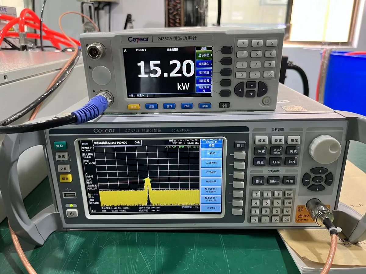
15 kW Microwave Generator Power & Spectrum-Related Test
Factory measurement evidence from a 15 kW industrial microwave generator. Formal regulatory EMC testing follows the applicable standard, equipment configuration and compliance route.
EMC Performance Depends on More Than the Generator
Final EMC behavior can change when the generator is integrated into a cabinet, machine, process chamber and site electrical environment. Several engineering factors need to work together.
Cabinet Shielding
Enclosure structure, openings and joints influence radiated-emission control.
Power-Line Filtering
Power interfaces may require appropriate filtering and installation coordination.
Signal Interfaces
Signal cable selection, filtering and routing influence conducted and radiated coupling.
Grounding & Bonding
Ground and bonding implementation form part of the complete installed EMC architecture.
Waveguide Interfaces
RF joints and mechanical interfaces influence microwave containment and unwanted RF paths.
Cable Routing
Separation and routing of power, control and signal cables can affect EMC performance.
Equipment Layout
Physical arrangement can influence coupling paths and the effectiveness of protective measures.
Final Installation
Site wiring, grounding and integration can affect the final equipment EMC result.
EMC Performance Belongs to the Assembled Configuration
Cabinet modifications, cable changes, waveguide routing, grounding and equipment layout can influence final EMC behavior. Generator-level engineering therefore needs to be coordinated with machine integration and the configuration used for final compliance verification.
CISPR 11 emission requirements, applicable immunity requirements and generator factory measurements answer different engineering questions. Define the formal EMC test plan around the actual equipment, operating condition and destination market.
Define Compliance Requirements for the Destination Market
Market compliance should be considered before the final equipment design is frozen. The applicable route depends on what product is being supplied, where it will be placed on the market and which requirements apply to that product.
Start with the Product Scope and Destination Market
A microwave generator, an RF subsystem and a complete industrial machine can have different compliance responsibilities. Define the product boundary first, then identify the applicable safety, EMC, RF, documentation and market-access requirements.
European Union and United States Follow Different Compliance Routes
The following workflows illustrate the engineering sequence. The exact requirements still depend on the final product, configuration and intended market.
European Union
Build conformity around the actual product and the EU requirements applicable to that product.
Define the Product Scope
Identify whether the supplied item is a generator, microwave subsystem or complete machine.
Identify Applicable EU Requirements
Determine which EU product rules and essential requirements apply to the actual equipment.
Risk & Technical Assessment
Identify relevant hazards, technical requirements and applicable standards.
Verification & Test Evidence
Complete the inspections, calculations and tests required by the conformity plan.
Technical Documentation
Compile the technical information needed to demonstrate conformity of the product.
EU Declaration of Conformity
Where required, the responsible manufacturer prepares and signs the applicable declaration.
CE Marking
CE marking is applied where the applicable EU product rules require it and the required conformity process has been completed.
United States
Review industrial microwave equipment within the applicable FCC Part 18 ISM framework.
Define the Equipment Scope
Identify the RF equipment being supplied and how it is intended to be used.
Confirm ISM Classification
Determine whether the equipment falls within the applicable FCC Part 18 ISM category.
Review FCC Part 18
Identify the requirements applicable to the selected industrial microwave equipment.
Frequency & RF Emissions
Evaluate operating frequency, applicable emission requirements and RF-control measures.
Technical Requirements
Address applicable construction, labeling, information and documentation requirements.
Equipment Authorization
Follow the authorization procedure applicable to the equipment category under the FCC rules.
Supplier's Declaration of Conformity
Non-consumer ISM equipment is subject to the FCC Supplier's Declaration of Conformity procedure under the applicable Part 18 rules.
CE Marking Is a Conformity Process — Not a Generic Certificate
Correct terminology matters when specifying or purchasing industrial microwave equipment for the European market.
Avoid Treating “CE Certified” as a Universal Generator Specification
CE marking applies to products covered by applicable EU legislation that requires the marking. The responsible manufacturer evaluates the actual product against the relevant requirements and maintains the supporting conformity documentation.
Build Evidence Around the Actual Product
Depending on the applicable product rules, the technical documentation can include information such as:
Non-Consumer ISM Equipment Uses the SDoC Authorization Procedure
Industrial microwave equipment intended for the U.S. market should be reviewed against the applicable FCC Part 18 requirements. For non-consumer ISM equipment, the current equipment-authorization route is the Supplier's Declaration of Conformity procedure.
Enclosure Protection Must Match the Installation
Market compliance also depends on the actual physical equipment configuration. Enclosure protection should therefore be selected from the real site and installation conditions.
Do Not Assume One IP Rating for Every Generator Configuration
The required enclosure protection depends on the selected cabinet, cooling arrangement and installation environment. Any stated IP rating should therefore match the specific product configuration and supporting evidence.
Three Compliance Terms That Should Not Be Confused
Clear terminology helps OEMs and procurement teams specify exactly what evidence they need from a microwave-equipment supplier.
Standard
A technical standard defines requirements, methods or engineering guidance for a defined scope. Referencing a standard is not automatically the same as holding a product certificate.
Test Evidence
Test reports and verification records demonstrate specific characteristics of a defined product configuration under the stated test conditions.
Market Conformity
Market conformity combines the applicable legal framework, product scope, assessment route, technical evidence and required manufacturer or responsible-party documentation.
Compliance follows the actual product and destination market—not a generic “CE/FCC certified microwave generator” label. Define the equipment scope, applicable requirements, verification evidence and documentation route before final market claims are made.
Convert Safety Requirements into a Testable Verification Plan
Safety and compliance requirements become useful engineering criteria when they can be translated into design reviews, functional checks, measurements, acceptance criteria and documented evidence. The verification plan should match the actual equipment scope and project requirements.
Six Stages from Requirement Review to Acceptance
Not every project requires the same tests. Define the verification matrix from the equipment boundary, destination market and customer specification.
Risk & Requirement Review
Define the equipment boundary, destination market, safety functions, applicable technical requirements and required acceptance evidence.
Design Review
Review relevant electrical architecture, RF transmission, shielding, cooling, interfaces and machine-integration requirements before final build.
Electrical & Functional Checks
Verify the agreed electrical, operating, control and protection functions for the supplied equipment.
Interlock & Safety Verification
Check the defined emergency-stop, guard, enable, cooling and fault-response functions within the agreed equipment boundary.
RF & EMC Verification
Perform the RF, leakage, emission, immunity or related checks required by the specific project and compliance plan.
FAT / SAT & Documentation
Complete the agreed acceptance activities and provide the project documentation required for shipment, installation or final handover.
Functional Verification Before Project Handover
Factory functional testing can verify the agreed generator-level operating and protection functions before shipment. The exact test scope should be defined from the supplied configuration and customer acceptance requirements.
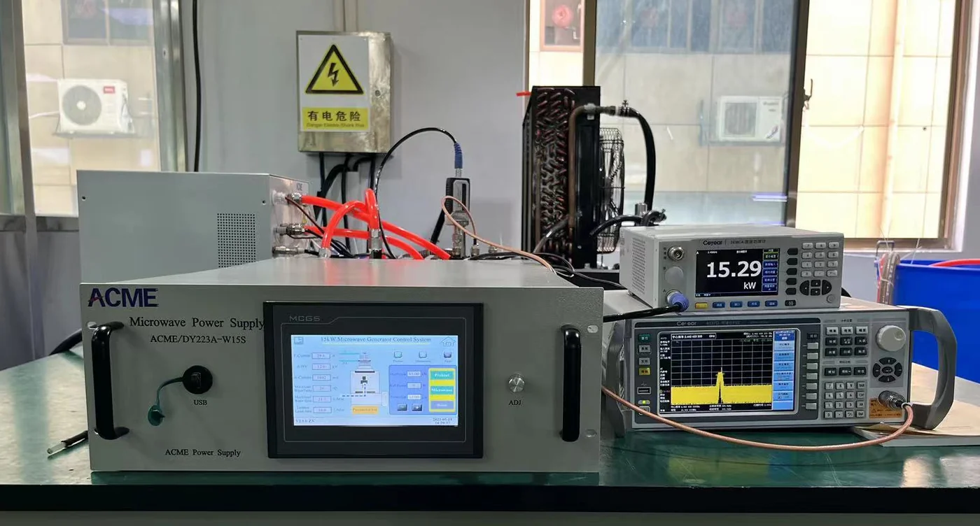
15 kW Microwave Generator Functional Test
Factory functional verification of a 15 kW industrial microwave generator. Project acceptance requirements are defined according to the supplied equipment and agreed test plan.
Build a Verification Matrix Around the Actual Project
A useful acceptance plan identifies what will be checked, where it will be checked and what evidence will be recorded. Generator-level factory testing and complete-machine testing may therefore have different scopes.
Define Required Records Before Shipment
Documentation expectations should be agreed early enough that required inspections, measurements and records can be incorporated into the project verification process.
Move from Compliance Planning to an Agreed Acceptance Test Matrix
MW-P18 defines why safety, RF, EMC and documentation requirements need verification. For a deeper review of factory acceptance, site acceptance and project test planning, continue to the dedicated microwave-generator FAT / SAT page.
Define the verification matrix before shipment. This keeps engineering requirements, acceptance criteria, responsibilities and documentation expectations aligned between the microwave-equipment supplier, OEM integrator and final project.

Industrial Microwave Generator Safety & Compliance FAQ
These answers address common questions about industrial microwave safety standards, RF leakage, EMC, machine interlocks, PL/SIL, CE marking and FCC Part 18 when integrating a microwave generator into industrial equipment.
Industrial microwave safety is evaluated at system level. The applicable standards, RF controls, machine safety functions, EMC tests and market-compliance requirements depend on the generator, RF path, complete machine, installation and destination market.
01 What safety standards apply to industrial microwave generators?
The applicable standards depend on the equipment boundary and final machine configuration. IEC 60519-1 provides a general safety framework for electroheating and electromagnetic processing equipment, while IEC 60519-6 addresses particular requirements for high-frequency dielectric and microwave heating and processing equipment.
Machine safety, functional safety, EMC and destination-market requirements may introduce additional applicable standards and regulatory requirements.
02 What is IEC 60519-6?
IEC 60519-6 is the microwave-specific part of the IEC 60519 safety framework. It addresses particular safety requirements for high-frequency dielectric and microwave heating and processing equipment.
It is used together with the relevant general safety requirements rather than as a stand-alone statement that an entire machine is automatically compliant.
03 What does CISPR 11 cover for industrial microwave equipment?
CISPR 11 addresses radio-frequency disturbance emissions from industrial, scientific and medical equipment. It provides requirements related to applicable emission limits and measurement methods.
EMC immunity is a separate question and should be evaluated under the applicable immunity requirements for the final product and environment.
04 Is CISPR 11 a certification?
No. CISPR 11 is a technical EMC emissions standard, not a generic product certification. Compliance claims should be based on the actual equipment, applicable test configuration, measurement method and supporting evidence.
05 Does FCC Part 18 apply to industrial microwave generators in the United States?
FCC Part 18 is the relevant U.S. regulatory framework for industrial, scientific and medical equipment that generates and uses RF energy for ISM purposes.
The actual equipment should be reviewed for its classification, operating frequency, emissions and applicable equipment-authorization requirements.
06 Is a 915 MHz industrial microwave generator permitted worldwide?
No. 915 MHz should not be assumed to have identical regulatory availability worldwide. The 902–928 MHz ISM allocation is associated with ITU Region 2, while national spectrum and equipment rules still need to be checked for the final destination.
For a 915 MHz project, the destination country should therefore be identified before the RF system design is finalized.
07 What is a microwave generator safety interlock?
A safety interlock is part of the control architecture used to permit or inhibit microwave operation according to defined equipment conditions.
Typical conditions may include protected access, machine enable, cooling availability or other project-defined operating conditions. The complete machine determines the final safety function.
08 How should a microwave chamber door interlock be designed?
The interlock should be designed from the machine risk assessment and the required safety function. The protected access condition, safety-related control logic, output action and microwave-source response need to be evaluated as one complete function.
The required architecture and performance cannot be determined from the microwave generator alone.
09 Does a microwave generator need a PL or SIL rating?
PL or SIL normally applies to a defined machine safety function and its complete implementation, not automatically to the microwave generator as a whole.
A generator interlock or inhibit interface can be one part of a safety-related control chain that also includes sensing, safety logic and final control elements.
10 How is microwave leakage measured on industrial equipment?
Microwave leakage is measured at accessible RF containment boundaries using the applicable test method and acceptance criteria for the equipment.
Relevant inspection locations can include:
- Waveguide flanges and joints
- Applicator or chamber interfaces
- Protected access doors
- Observation windows
- Service panels
- Other project-specific RF openings
Final measurement is most meaningful on the assembled microwave system.
11 What affects EMC performance in an industrial microwave system?
EMC performance depends on the complete installed configuration, not only on the microwave generator. Important factors can include:
- Cabinet shielding
- Power-line filtering
- Signal interfaces
- Grounding and bonding
- Waveguide joints
- Cable routing
- Equipment layout
- Final site installation
12 What is an EU Declaration of Conformity?
An EU Declaration of Conformity is the manufacturer's declaration that the identified product meets the applicable EU requirements covered by the declaration.
It forms part of the applicable conformity process together with product identification, technical documentation and supporting assessment evidence.
13 Is “CE certified microwave generator” the correct terminology?
“CE certified” is not the best general description of the EU conformity process. CE marking is applied to products that fall under applicable EU legislation requiring the marking after the required conformity assessment and documentation process has been completed.
The correct assessment depends on the actual product being supplied and the EU requirements applicable to it.
14 What IP rating does an industrial microwave generator require?
There is no single IP rating that automatically applies to every industrial microwave generator. The required enclosure protection depends on the specific cabinet, cooling arrangement and installation environment.
Indoor or outdoor use, dust, moisture, ambient conditions and service requirements should be considered when defining the enclosure configuration.
15 What information is needed for a microwave generator compliance review?
Start with the actual equipment configuration, operating frequency and destination market. Useful project information includes:
- Generator power and frequency
- 2450 MHz or 915 MHz operation
- Destination country or region
- Generator, subsystem or complete-machine scope
- Microwave head and waveguide configuration
- Applicator or process chamber
- Electrical supply
- Cooling arrangement
- Machine safety and interlock requirements
- Required RF / EMC tests
- FAT / SAT requirements
- Required technical documentation
Compliance Starts with the Actual Equipment
There is no single safety or compliance label that defines every industrial microwave project. Start with the equipment boundary, frequency, RF architecture, machine safety functions, installation and destination market, then build the applicable standards, verification and documentation plan.
Have a Safety, EMC or Market-Compliance Requirement?
Send your generator power, frequency, destination market, equipment scope and required tests for an engineering review.
Send Your Microwave Project Requirements for Engineering Review
Provide the core project information so the generator, RF architecture, safety interfaces, verification plan and destination-market requirements can be reviewed against the actual equipment scope.
You Do Not Need a Finished Compliance Specification to Contact Us
Start with the information already available. Open technical items can then be identified during the engineering review.
Include These Project Inputs Where Available
The required detail depends on whether the project involves a generator, microwave subsystem, OEM integration or complete industrial equipment.
Microwave Generator
Define the required microwave source and main operating range.
Destination Market
Identify where the equipment will be placed, installed or operated.
RF System
Describe how microwave energy will be transferred to the process.
Electrical & Installation
Provide the available site and utility conditions for integration.
Machine Safety
Identify the machine interfaces and safety-related functions relevant to microwave operation.
EMC & RF Verification
State any specified RF, leakage, emission or immunity requirements.
FAT / SAT Requirements
Define the expected factory and site acceptance scope where known.
Required Documentation
Identify the documents expected with the equipment or project.
From Project Inputs to an Engineering Scope
The objective is to identify the generator configuration, integration boundary and verification requirements early, before critical RF, machine or compliance decisions are locked.
Review Project Inputs
Confirm power, frequency, destination market, equipment boundary and process requirements.
Define Engineering Interfaces
Identify RF, electrical, cooling, control and machine-integration requirements.
Align Verification Scope
Establish the required tests, acceptance activities and project documentation.
Send the Available Project Information to SDACME
Include your required microwave power, frequency, destination market, RF system and any known safety, EMC or acceptance requirements. The engineering discussion can then focus on the actual project configuration.
