Partial Discharge-Free Power Supply Manufacturer

Partial Discharge-Free Power Supply for Transformer Testing

SDACME manufactures variable-frequency AC test power supplies for transformer partial-discharge and induced-voltage testing, providing controlled voltage, frequency and transformer-isolated sine-wave output for demanding transformer test applications.
5–2000 kVA Available capacity range
45–200 Hz Reference output frequency
0–1000 V Reference L-L output voltage
Transformer Test Power PD and induced-voltage applications
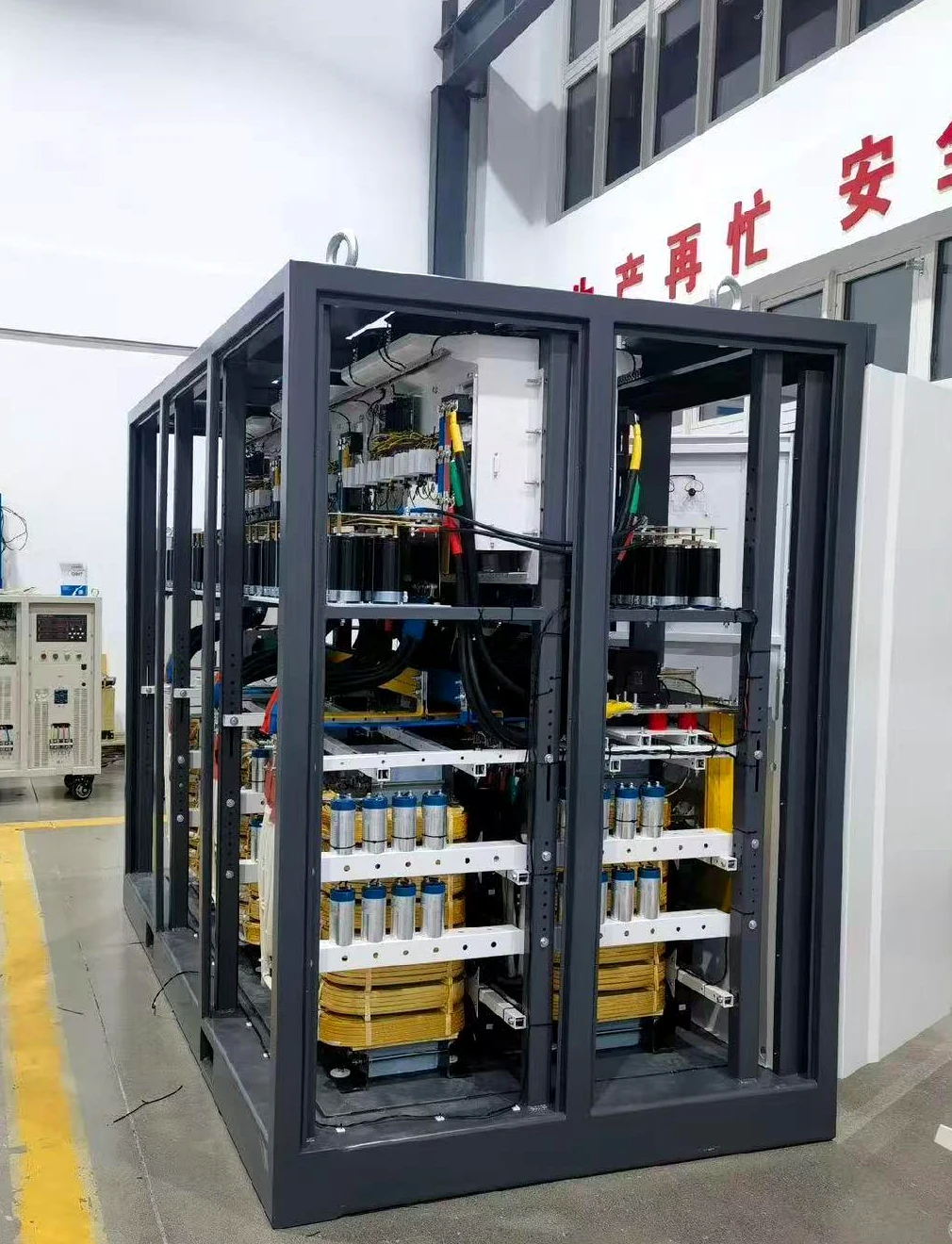
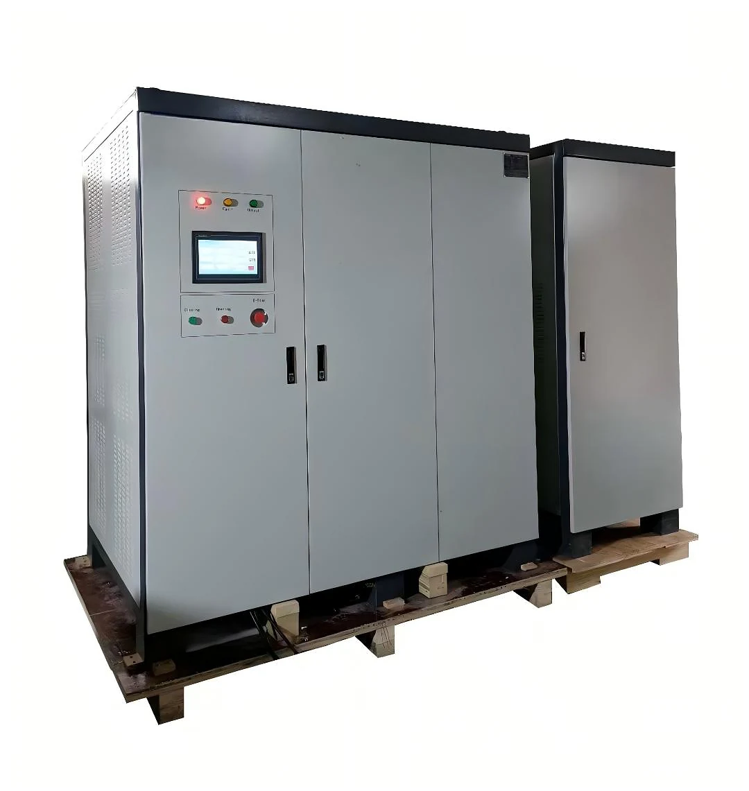
SDACME partial discharge-free power supply cabinet
Partial Discharge-Free Power Supply SDACME
Manufacturer Transformer Test Power Project Configuration
Transformer Test Power Source

Variable-Frequency Test Power for Transformer Applications

SDACME partial discharge-free power supplies are designed as AC test power sources for transformer testing where adjustable voltage, frequency, waveform quality and controlled test conditions are required.
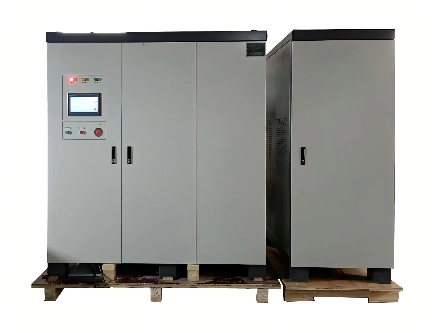
Front view of SDACME partial discharge-free frequency converter
Partial discharge-free frequency converter for transformer test power applications.

Test Power Source — Not the PD Measuring Instrument

The frequency converter supplies controlled AC excitation to the transformer test circuit. Partial-discharge detection and measurement are performed by the corresponding measurement equipment used in the complete test arrangement.

Primary Role Controlled Test Power

Adjustable AC voltage and frequency for applicable transformer test requirements.

System Boundary Works With Test Equipment

Measurement, sensing and other test-system components are configured according to the required test arrangement.

Supported Transformer Test Power Applications
  • Partial Discharge Testing
  • Induced Withstand Voltage Testing
  • No-Load Loss Testing
  • Load Testing
  • Temperature-Rise Testing
Need to match the power source to a specific transformer test? Send the transformer and test requirements for configuration review.
Send Test Requirements →
Technical Performance

Series Scope and Reference Electrical Specifications

The SDACME partial discharge-free power supply series covers a wide capacity range for transformer test power applications. Final electrical configuration is reviewed against the required transformer and test conditions.

Series Capacity 5–2000 kVA

Available capacity range stated for the partial discharge-free frequency converter series.

Product Type Variable-Frequency AC Test Power

Designed as the controllable power source for applicable transformer testing requirements.

Main Test Applications PD & Induced-Voltage Testing

Also applicable to selected no-load, load and temperature-rise test power requirements.

Reference Configuration

Electrical Performance for Project Evaluation

The values below represent the reference electrical configuration used for project evaluation. Final interfaces are confirmed against the selected equipment configuration.

Input Phase Three-phase, three-wire + ground
Reference Input Voltage 480 V ±10%
Reference Input Frequency 60 Hz ±5 Hz
Input Power Factor >0.92
Output Phase Three-phase, four-wire + ground
Output Isolation Transformer isolated
Reference Output Voltage 0–1000 V L-L
Voltage Stability ≤±1%
Reference Output Frequency 45.0–200.0 Hz
Frequency Adjustment 0.1 Hz
Frequency Stability ≤±0.01%
Source-Voltage Effect ≤±1%
Load Effect ≤±1%
Output Waveform Sine wave
Waveform Distortion ≤3% under resistive load
Three-Phase Angle 120° ±1°
Efficiency ≥88%
✓
Final Configuration Is Matched to the Test Requirement

Input conditions, required output voltage, test frequency, capacity and phase arrangement should be reviewed together with the transformer test requirement before the final equipment configuration is defined.

Need to confirm the electrical configuration for your project? Send the transformer and test requirements to SDACME for configuration review.
Request Configuration →
Transformer Test Applications

Test Power for Partial Discharge and Induced-Voltage Applications

SDACME partial discharge-free power supplies provide controlled variable-frequency AC power for transformer test arrangements where stable excitation, adjustable frequency and electrical isolation are required.
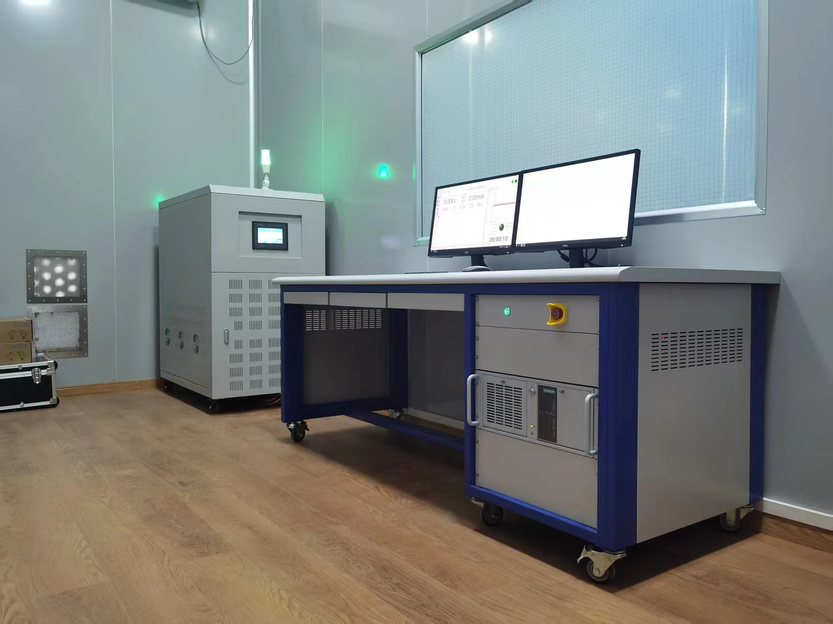
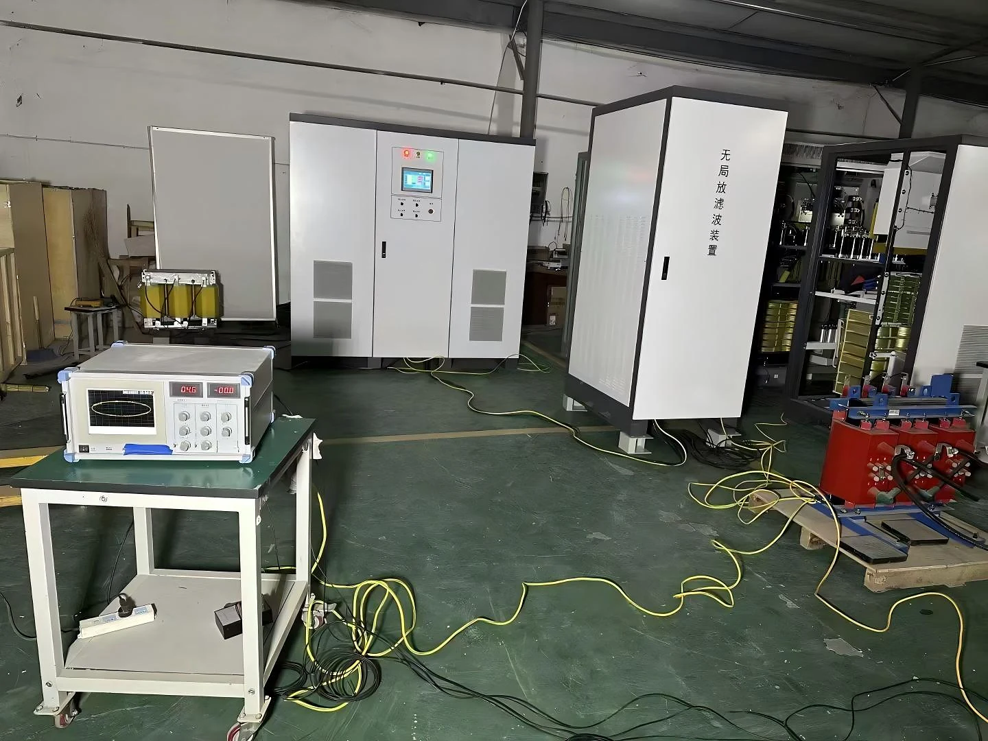
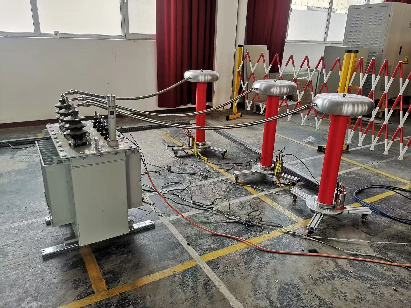
Transformer test area with variable-frequency test power equipment Primary Application

Partial Discharge Testing

The power supply provides adjustable AC excitation for transformer partial-discharge test arrangements, serving as the controlled test power source used together with the required measurement equipment.

  • Variable-frequency AC excitation
  • Transformer-isolated output
  • Controlled voltage and frequency
  • Designed for transformer test power applications
Learn about the transformer partial discharge test →
High-voltage transformer test setup with test power equipment Primary Application

Induced Withstand Voltage Testing

Adjustable-frequency output supports transformer induced-voltage and induced-withstand test requirements where the excitation frequency and test voltage must be matched to the selected test arrangement.

  • Adjustable test frequency
  • Controlled AC test voltage
  • Sine-wave output
  • Project configuration based on test requirements
Learn about the transformer induced voltage test →
Additional Test Power Duties

Additional Transformer Test Applications

The same power source can also support selected transformer test duties when the required electrical conditions match the configured power-supply capability.

01
No-Load Loss Testing

Provides AC test power for applicable transformer no-load test arrangements.

02
Load Testing

Can provide the required test power source for selected transformer load test configurations.

03
Temperature-Rise Testing

Supports applicable transformer temperature-rise test power requirements according to the selected configuration.

i
The Power Supply Is One Part of the Complete Test Arrangement

Test measurement, sensing, transformer connections and other test-system components are selected according to the required test method and project configuration.

Which transformer test do you need to perform? Send the test type, transformer information and required electrical conditions for configuration review.
Discuss Your Test Requirement →
Test Power Quality

Controlled AC Power for Sensitive Transformer Test Conditions

Transformer partial-discharge and induced-voltage testing place particular requirements on the excitation power source. Output waveform, voltage stability, frequency stability, electrical isolation and output conditioning all contribute to a controlled transformer test environment.

More Than Basic Frequency Conversion

The purpose of the test power source is not simply to change frequency. It must provide a controlled AC output suitable for the selected transformer test arrangement.

01
Controlled Sine-Wave Output

Sine-wave output supports transformer test excitation where waveform quality is an important part of the test power requirement.

02
Electrical Isolation

Transformer-isolated output separates the configured test output from the incoming supply as part of the test power architecture.

03
Output Conditioning

The power conversion and output conditioning stages are designed to provide controlled AC power for applicable transformer test requirements.

04
Stable Voltage & Frequency

Controlled voltage and frequency help maintain the required excitation conditions throughout the selected test procedure.

Test Evidence Monitoring screen during transformer test power verification
Test Monitoring During Equipment Verification Actual test instrumentation is used as verification evidence; individual screen readings are not presented as series-wide rated performance.
Reference Performance

Key Output Characteristics

≤±1% Reference voltage stability
≤±0.01% Reference frequency stability
≤3% Waveform distortion under resistive load
Sine Wave Reference output waveform
i
Test Performance Depends on the Complete Test Arrangement

The power supply provides the excitation source. Final measurement performance also depends on the transformer under test, measurement equipment, test connections, grounding and the overall test setup.

Need a controlled power source for transformer PD or induced-voltage testing? Send your transformer rating, test type, required voltage and frequency for configuration review.
Request Configuration →
System Architecture

Controlled Power Conversion from Grid Input to Transformer Test Output

The partial discharge-free power supply converts the incoming AC supply into a controlled, electrically isolated and conditioned variable-frequency AC output for the selected transformer test requirement.

Public System View

Power Conversion Architecture

The public architecture below shows the functional power path used to explain system capability without exposing internal control, circuit or component-level implementation details.

01
AC Input Incoming facility power enters the configured test power system.
02
Input Conditioning The incoming supply is conditioned before controlled power conversion.
03
Controlled Power Conversion Electrical power is converted to provide adjustable output conditions.
04
Electrical Isolation The test output is electrically isolated as part of the configured power architecture.
05
Output Conditioning Output conditioning supports the required waveform and controlled test power characteristics.
06
Variable-Frequency Test Output Controlled AC output is supplied to the selected transformer test arrangement.
01
Adjustable Test Conditions

Output voltage and frequency can be matched to the applicable transformer test requirement within the selected configuration.

02
Isolated Test Output

Electrical isolation forms part of the power path between the incoming supply and the transformer test output.

03
Conditioned AC Output

The final output stage provides controlled sine-wave test power for applicable transformer testing.

i
System Configuration Is Defined Around the Required Test Duty

The final power path, electrical interfaces and equipment configuration are selected according to the transformer rating, available input supply, required output conditions and intended test application.

Need to configure the test power architecture for your transformer? Send the available input supply, transformer information and required test conditions for project configuration review.
Request Configuration →
Configuration Selection

Configure the Power Source Around the Transformer Test Requirement

The appropriate partial discharge-free power supply is selected from the actual transformer test duty, required electrical conditions and available facility supply. Capacity alone is not sufficient to define the final equipment configuration.

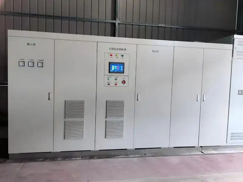
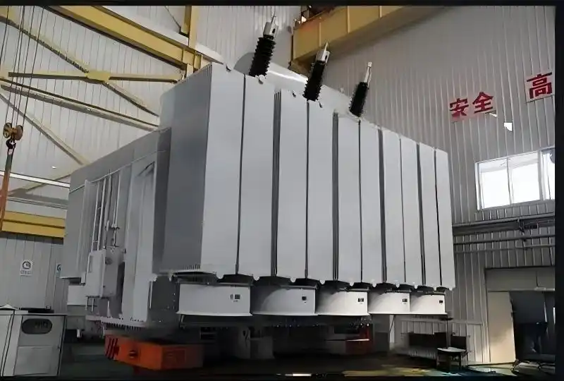
5–2000 kVA Available series capacity range
From lower-capacity laboratory requirements to large transformer test power configurations

The series capacity range provides a starting point for equipment selection. Final configuration is reviewed against the intended test application and required output conditions.
Information for Selection

What Should Be Confirmed Before Quotation?

Providing the following project information helps SDACME review the required power-source configuration before preparing a quotation.

01
Test Type Partial discharge, induced withstand voltage, or another supported transformer test duty.
02
Transformer Rated Capacity Provide the transformer rating and basic nameplate information when available.
03
Transformer Voltage Level Identify the relevant winding voltage or test-side voltage information.
04
Available Input Supply Facility input voltage, frequency and phase arrangement.
05
Required Output Voltage Target test voltage or required output range when already defined.
06
Required Test Frequency Test frequency or required frequency range for the intended procedure.
07
Existing Test Equipment Relevant measurement, transformer connection or test-system information if applicable.
01
Start with the Test Duty

Define what transformer test must be performed before selecting the required test power source.

02
Match the Electrical Conditions

Review available input power together with the required voltage, frequency, phase and output conditions.

03
Confirm the Project Configuration

The selected equipment configuration is defined after the actual transformer and test requirements are reviewed.

i
Capacity Selection Is Based on the Complete Test Requirement

Transformer rated capacity alone does not define the required power supply rating. Test type, test voltage, frequency, transformer characteristics and the complete test arrangement should be reviewed together before final equipment selection.

Send Your Transformer Test Requirements

Provide the available project information and SDACME will review the appropriate partial discharge-free power supply configuration for quotation.

Request a Configuration →
Control, Monitoring & Protection

Local HMI Monitoring with Integrated Electrical Protection

The partial discharge-free power supply provides local operating visibility for key electrical parameters together with integrated protection functions for controlled transformer test power operation.

Key Electrical Parameters at the Operator Interface

The local interface provides the operator with the principal electrical information required to monitor the configured test power output during operation.
V
Output Voltage Local display of the configured AC output voltage.
Hz
Output Frequency Monitoring of the active variable-frequency test output.
A
Output Current Current indication supports operating-condition monitoring.
kW
Output Power Power information provides additional visibility into test operation.
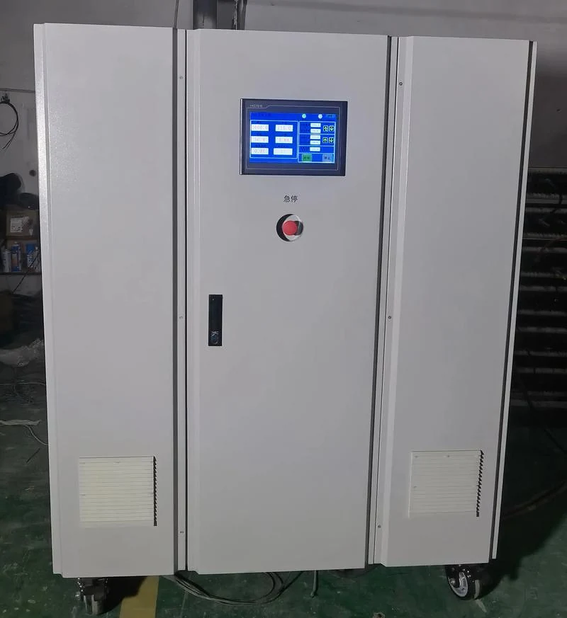
Local HMI HMI control interface on partial discharge-free power supply
Operator Interface for Local Monitoring Actual equipment interface used for operating and monitoring the configured test power system.
10-inch Reference color LCD touchscreen
Clear Local Interaction for Test Power Operation

The reference configuration uses a color touchscreen for local operation and parameter monitoring. Final interface details follow the selected equipment configuration.

Electrical Protection Functions

Protection functions are integrated into the equipment to support controlled operation under abnormal electrical or thermal conditions.

01
Overcurrent Protection Protection for abnormal current conditions.
02
Short-Circuit Protection Protection response for short-circuit conditions.
03
Overload Protection Protection for equipment overload conditions.
04
Overtemperature Protection Thermal protection supports equipment operation.
05
Emergency Stop Local emergency-stop control is provided for operator access.
01
Local Control

The operator interface provides local access to the principal operating functions of the configured system.

02
Status Indication

Operating information and system status are presented to support equipment monitoring during the transformer test process.

03
Power-Failure Output

The reference technical configuration includes power-failure output and indication functions as part of equipment operation.

i
Protection and Control Are Matched to the Selected Equipment Configuration

Public product information describes the available monitoring and protection functions. Detailed protection settings, control logic and project-specific operating parameters are defined for the selected equipment configuration.

Need to review the operating and protection requirements for your test system? Send the transformer test duty and required electrical conditions for project configuration review.
Discuss Your Requirements →
SDACME Manufacturing

Manufactured and Factory-Tested for Transformer Test Power Applications

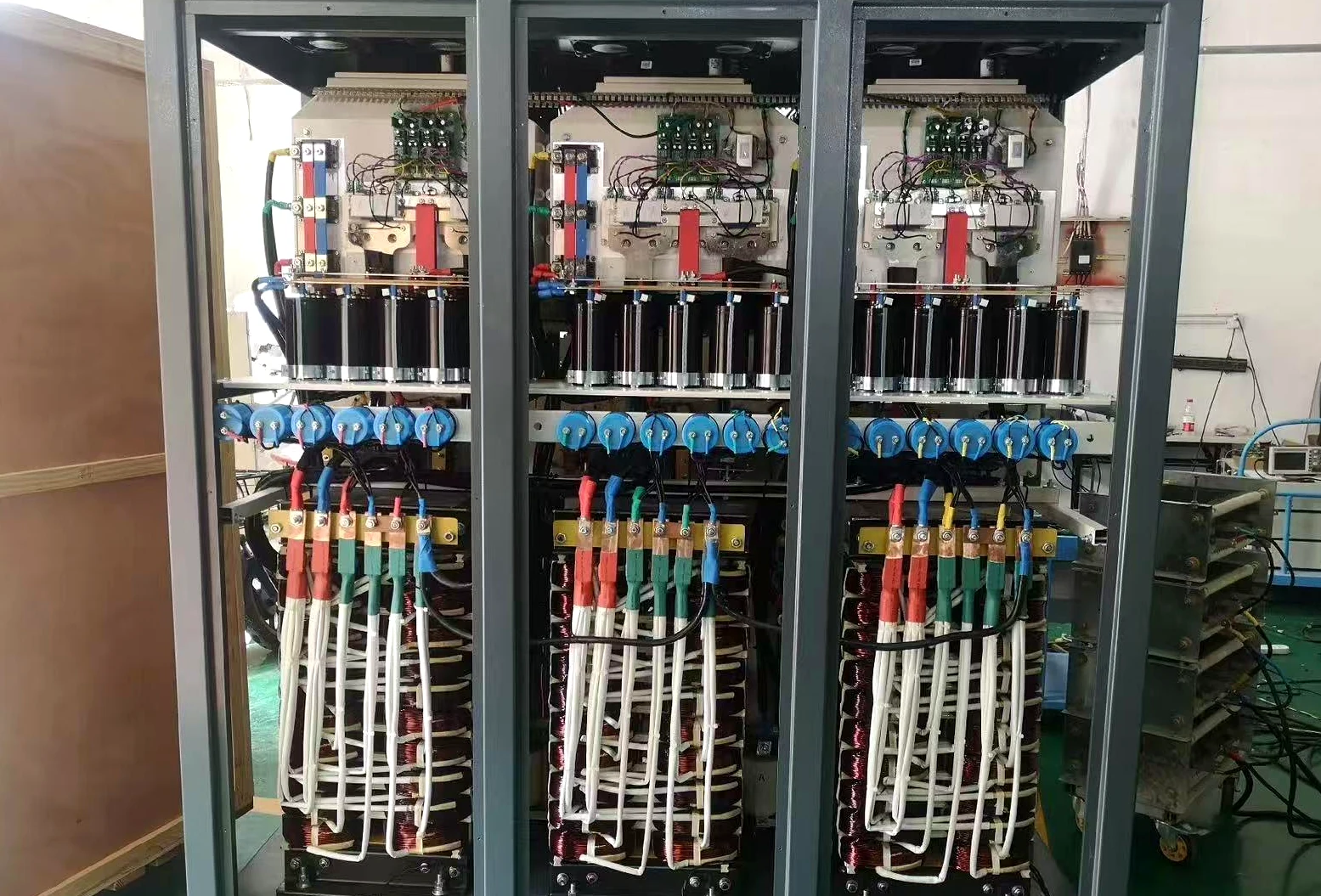
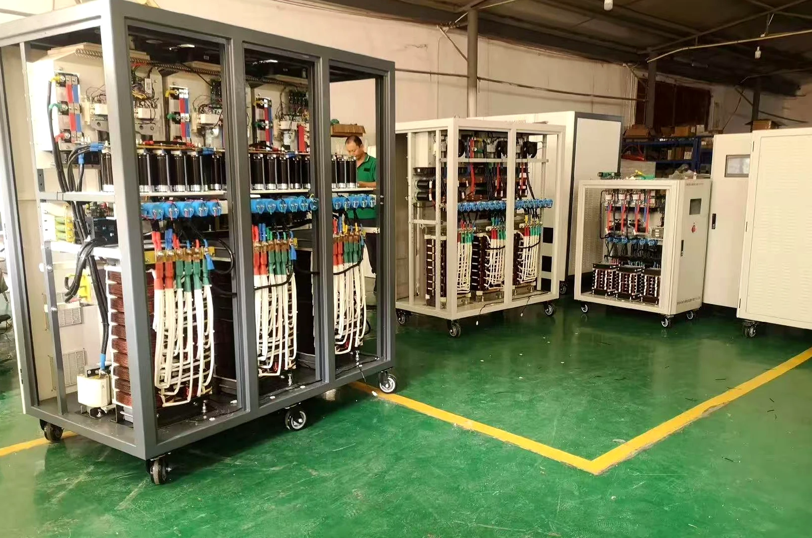
SDACME manufactures partial discharge-free frequency converter systems for transformer test power applications, from cabinet assembly and equipment integration through factory verification and preparation for delivery.
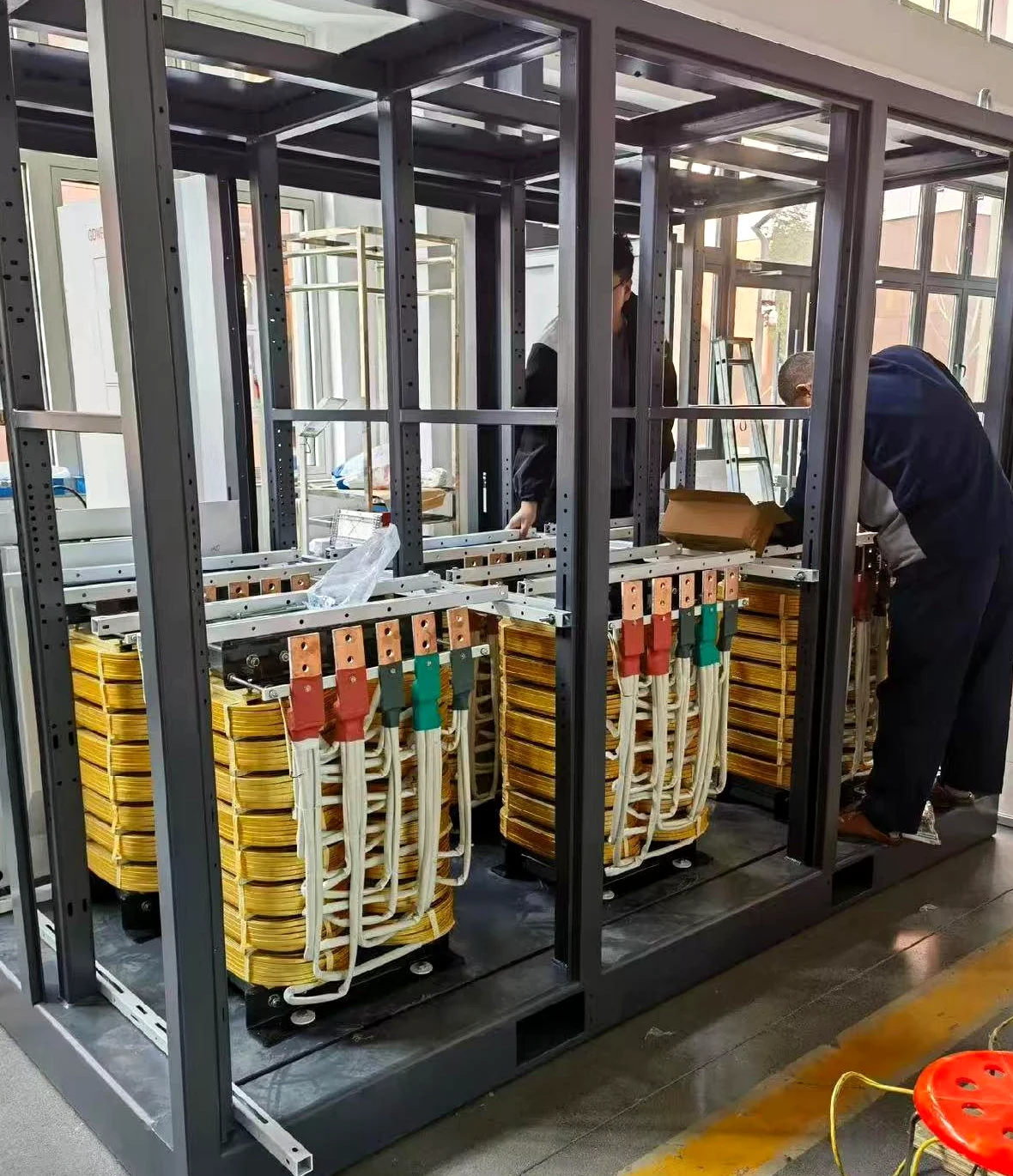
Factory Assembly Partial discharge-free power supply assembly in progress at SDACME factory
Power Supply Equipment During Factory Assembly

Actual workshop equipment showing cabinet assembly and manufacturing work in progress.

Manufacturer Capability

From Equipment Assembly to Factory Verification

Each project begins with the required transformer test duty and electrical configuration. The equipment is then prepared around the selected capacity, test conditions and project interfaces.

  • Power conversion cabinet assembly
  • Configured equipment integration
  • Local control and monitoring interface
  • Factory equipment verification
  • Preparation for project delivery
Project Flow

From Requirement Review to Factory Test

The manufacturing process follows the selected transformer test requirement and equipment configuration through assembly, integration and factory verification.

01
Requirement Review

Transformer information, test duty and required electrical conditions are reviewed before equipment configuration.

02
Equipment Assembly

Power supply cabinets are assembled according to the selected project configuration.

03
System Integration

Control, monitoring and the required equipment functions are integrated into the configured system.

04
Factory Verification

The completed equipment is checked and tested before preparation for delivery.

✓
Factory Test Documentation

Factory test documentation is included with the referenced partial discharge-free frequency converter equipment package.

Looking for a partial discharge-free power supply manufacturer? Send your transformer test requirements to SDACME for equipment configuration and quotation.
Contact SDACME →
Real Equipment & Project Evidence

From Test Environment to Equipment Delivery

Real equipment, transformer test environments and delivery preparation provide practical evidence behind the SDACME partial discharge-free power supply product line.
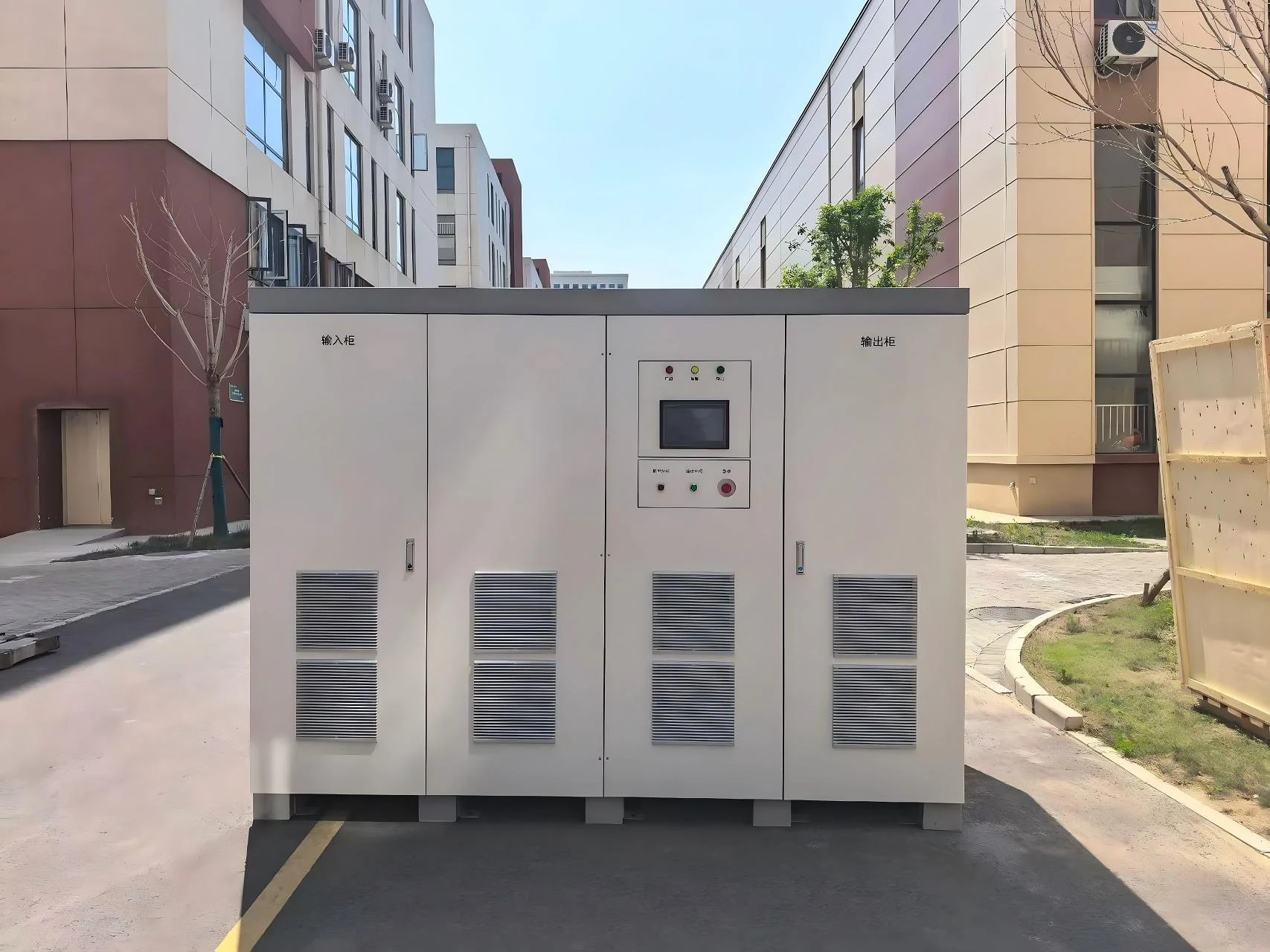
Real Equipment Actual manufactured power supply systems.
Test Environment Equipment used in transformer-related test arrangements.
Large Capacity Reference equipment within the stated series range.
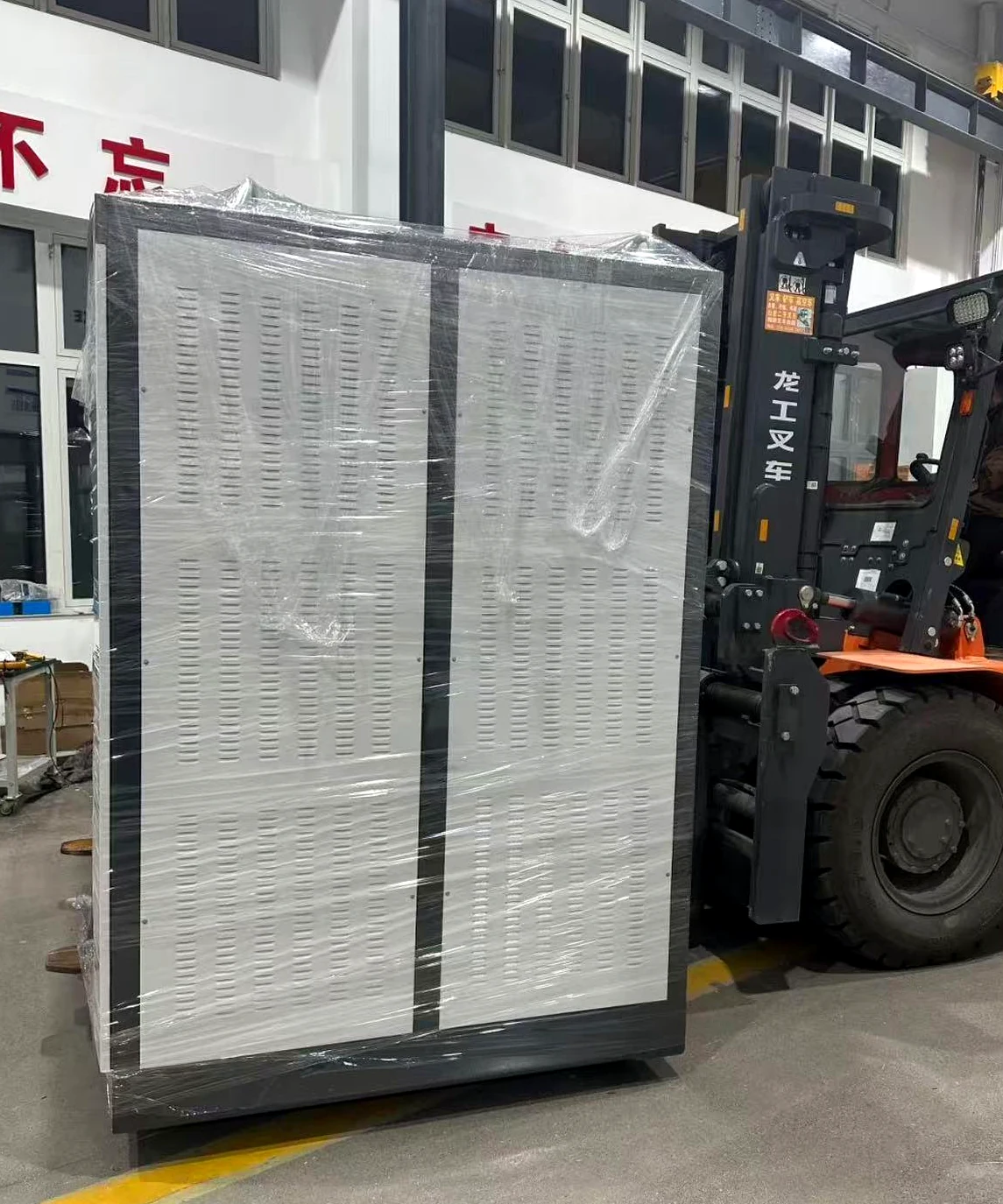
Delivery Preparation Finished equipment prepared for shipment.
Evidence Chain

What These Images Demonstrate

01
Physical Equipment

The product is represented by actual manufactured systems rather than conceptual product renderings.

02
Transformer Test Use

Test-area evidence supports the product positioning as a power source for transformer test applications.

03
Manufacturing to Delivery

Combined with the factory evidence above, the page documents the path from manufacturing through testing and shipment preparation.

i
Project Configuration Is Confirmed Against the Actual Test Requirement

The equipment shown represents real manufactured and test-related examples. Final capacity, electrical interfaces and test conditions are defined according to the selected project configuration.

Have a transformer test power requirement? Send your transformer information, test type and required electrical conditions for configuration review and quotation.
Request a Configuration →
Frequently Asked Questions

Partial Discharge-Free Power Supply FAQ

Key answers for transformer manufacturers, test laboratories and engineering teams evaluating a variable-frequency AC power source for partial-discharge and induced-voltage testing.

5–2000 kVA Available series capacity range
45–200 Hz Reference output-frequency range
0–1000 V L-L Reference output-voltage range
What is a partial discharge-free power supply?

A partial discharge-free power supply is a variable-frequency AC test power source used in transformer test arrangements that require controlled voltage, frequency, waveform and electrical isolation.

SDACME equipment is intended to provide the excitation power required for transformer partial-discharge and induced-voltage test applications, with the final configuration selected around the required test duty.

Is a partial discharge-free power supply the same as a partial-discharge detector?

No. The power supply provides the AC excitation source; the partial-discharge detector or measurement system performs the actual PD measurement.

In a complete transformer test arrangement, the power source, measurement equipment, transformer connections and other test components work together according to the selected test method.

What capacity range is available?

The stated SDACME partial discharge-free frequency converter series covers a capacity range of 5 kVA to 2000 kVA.

Final equipment capacity is selected from the complete transformer test requirement rather than transformer rated capacity alone.

What output voltage and frequency are available?

The reference electrical configuration specifies an output-voltage range of 0–1000 V line-to-line and an output-frequency range of 45–200 Hz.

Final electrical interfaces and required operating conditions are reviewed against the selected equipment configuration and the intended transformer test.

What transformer tests can the power supply support?

The primary applications are transformer partial-discharge testing and induced-withstand-voltage testing.

The technical solution also identifies applicable power-supply use for selected transformer no-load loss, load and temperature-rise test duties.

  • Partial discharge testing
  • Induced withstand voltage testing
  • No-load loss testing
  • Load testing
  • Temperature-rise testing
Why does the test power source matter in transformer partial-discharge testing?

The excitation source establishes the electrical conditions applied to the transformer during the test.

Output waveform, voltage and frequency stability, electrical isolation and output conditioning are therefore important considerations when selecting power equipment for a sensitive transformer test arrangement.

What information should I provide for configuration and quotation?

Start with the transformer information, intended test duty and the required electrical conditions.

  • Test type
  • Transformer rated capacity
  • Transformer voltage level
  • Available input voltage, frequency and phase
  • Required output voltage
  • Required test frequency
  • Existing test equipment or test arrangement, if applicable

SDACME can then review the required partial discharge-free power supply configuration before quotation.

Still evaluating the correct test power configuration? Send the available transformer and test information for project configuration review.
Send Test Requirements →
Request a Configuration

Need a Partial Discharge-Free Power Supply for Your Transformer Test?

Send SDACME your transformer test requirements and required electrical conditions. We will review the application and prepare the appropriate power-supply configuration for quotation.

Start with the Available Project Information

You do not need to define the complete power-supply configuration before contacting us. The following information provides a practical starting point for technical review.

01
Test Type Partial discharge, induced voltage or another supported test duty.
02
Transformer Rating Rated capacity and relevant transformer voltage information.
03
Available Input Supply Facility voltage, frequency and phase arrangement.
04
Required Test Voltage Required output voltage or target range when known.
05
Required Test Frequency Target frequency or operating frequency range when defined.
06
Existing Test Arrangement Relevant test equipment or connection information if available.
Talk to the Manufacturer

Request Your Project Configuration

SDACME manufactures partial discharge-free power supplies for transformer test applications. Submit the project conditions for configuration review and quotation.

5–2000 kVA available series range
Transformer PD and induced-voltage test applications
Project-based electrical configuration
Factory manufacturing and test evidence
What happens next? Your transformer and test requirements are reviewed before the equipment configuration and quotation are prepared.
Manufacturer Real factory and assembly evidence
Transformer Testing PD and induced-voltage applications
5–2000 kVA Available series capacity range
Project Configuration Matched to the required test duty