
移动式岸上电力变电所用于灵活的泊位服务
A mobile shore power system is not defined by wheels or lifting points alone. Its value depends on whether repeated relocation improves berth operation without creating unacceptable capacity, interface, protection or maintenance constraints.
A mobile shore power substation is justified when relocating the electrical package is part of normal berth operation—not merely something the equipment can physically survive.
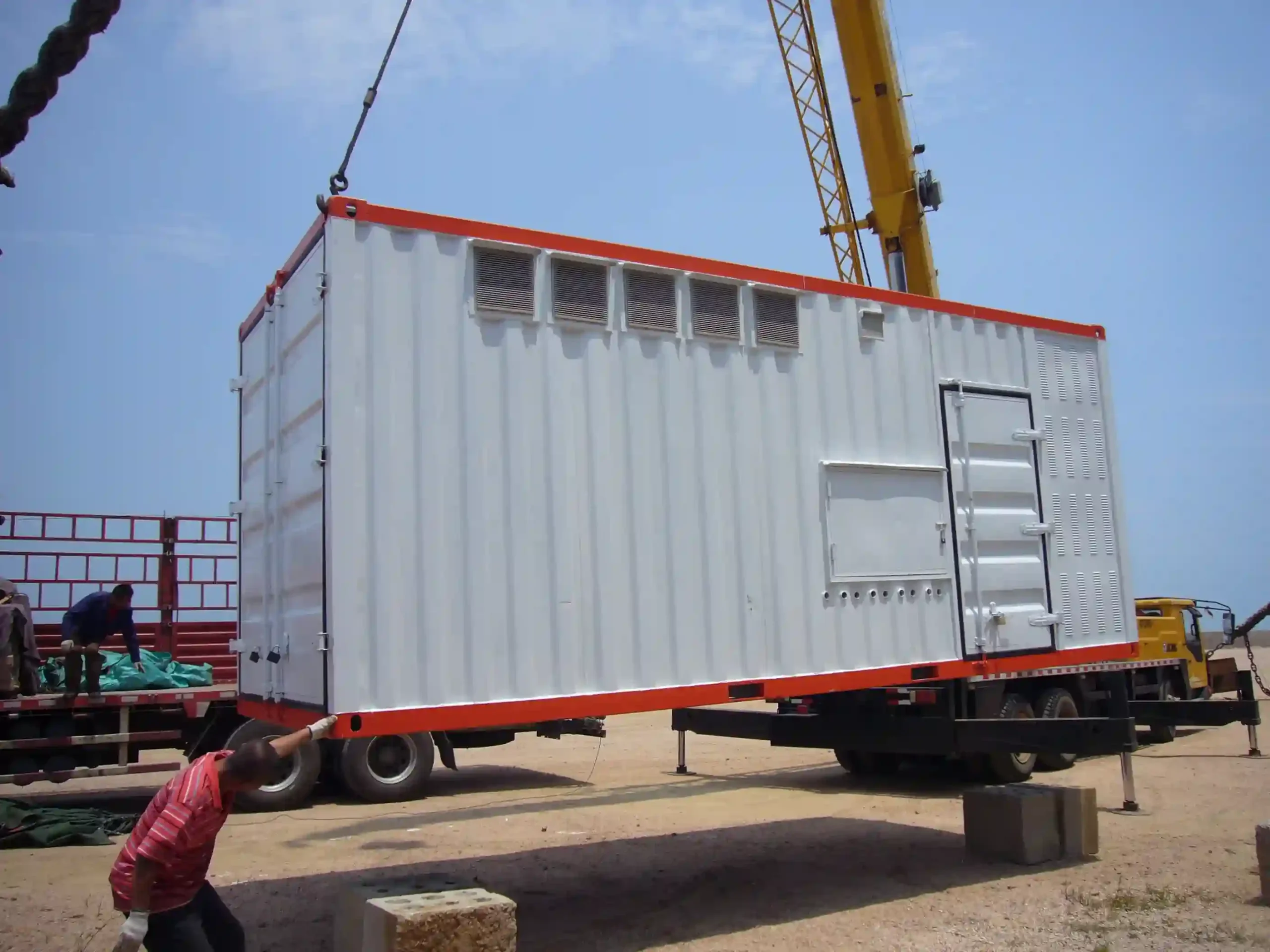
A container with lifting points may be transportable, but that does not automatically make it an operationally mobile shore power system. If every move requires a crane, temporary cable work, extensive retermination and another major commissioning exercise, the equipment may technically be movable while remaining operationally fixed.
A genuinely mobile arrangement is different. Its route, stopping positions, incoming and outgoing interfaces, protective-earth connection, cable handling, securing method, control logic and post-relocation checks are designed around repeated movement from the beginning.
It is “Does repeated movement improve the berth operation enough to justify the additional interfaces, maintenance and operating steps?”
Why Mobile Shore Power Exists
Mobility normally addresses an infrastructure-utilization problem.
A port or shipyard may have several locations where vessels require shore power, while the demand at those positions does not occur simultaneously. Installing a complete transformer or conversion package at every berth can then duplicate expensive equipment that spends much of its time idle.
One shared package can offer another architecture. The electrical equipment remains a single resource, but the resource changes operating position according to the vessel schedule.
This can be useful for:
- adjacent berths with non-simultaneous demand;
- shipyard work locations that change with docking activity;
- phased infrastructure upgrades;
- temporary service during construction or refurbishment;
- sites where permanent electrical equipment at every berth is difficult to justify.
The benefit, however, is not simply “flexibility”.
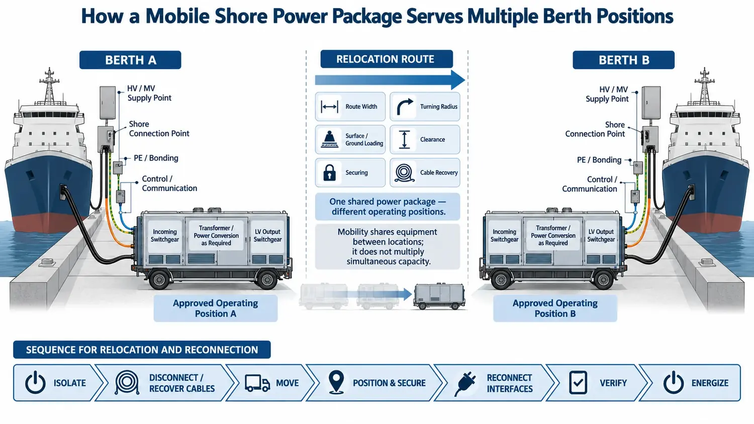
Every relocation creates another sequence of isolation, disconnection, cable recovery, movement, positioning, reconnection and verification.
That trade-off should be evaluated before the chassis is selected.
For installations that remain in one operating position, our 集装箱式岸上供电系统 page explains the fixed containerized approach in more detail.
Transportable, Mobile and Fixed Are Different Deployment Concepts
These terms are often treated as interchangeable, but they lead to different engineering decisions.
| Deployment | Normal operating assumption | Main engineering consequence |
|---|---|---|
| Fixed | Equipment remains in one installed operating position. | Cables, earthing, protection, ventilation, access and maintenance are optimized around that location. |
| Transportable | Equipment can be relocated, but movement is exceptional rather than routine. | Crane lifting, cable retermination or substantial site work may still be acceptable. |
| Operationally mobile | Relocation is expected as part of normal service. | Carrier, route, connection interfaces, operating states and post-movement verification must support repeated relocation. |
For a transportable container, lifting and structural integrity may be enough to prove that relocation is physically possible.
For a mobile shore power package, the project must also prove that relocation is repeatable, electrically controlled and operationally practical.
The wider distinction can also be reviewed under containerized vs mobile shore power systems.
Start With the Vessel Schedule Before Selecting the Mobile Equipment
The operating schedule determines whether shared mobile capacity is useful.
Consider two adjacent berths, each capable of receiving a vessel requiring 500 kVA. If the vessels normally require shore power at different times, one 500 kVA mobile package may potentially serve both positions sequentially.
But mobility does not multiply capacity.
If both vessels require 500 kVA at the same time, the problem has changed from equipment relocation to simultaneous capacity.
The project may then require:
- two independent power packages;
- a larger centralized source with multiple feeders;
- another shared distribution architecture;
- or operational restrictions on simultaneous connection.
The number of sockets along the quay should never be confused with the amount of electrical capacity available behind them.
A Real 500 kVA Two-Berth Engineering Configuration
A two-berth engineering configuration provides a useful example of how mobility changes the complete system rather than only the enclosure.
The arrangement was developed around adjacent berth positions and a 500 kVA mobile transformer package.
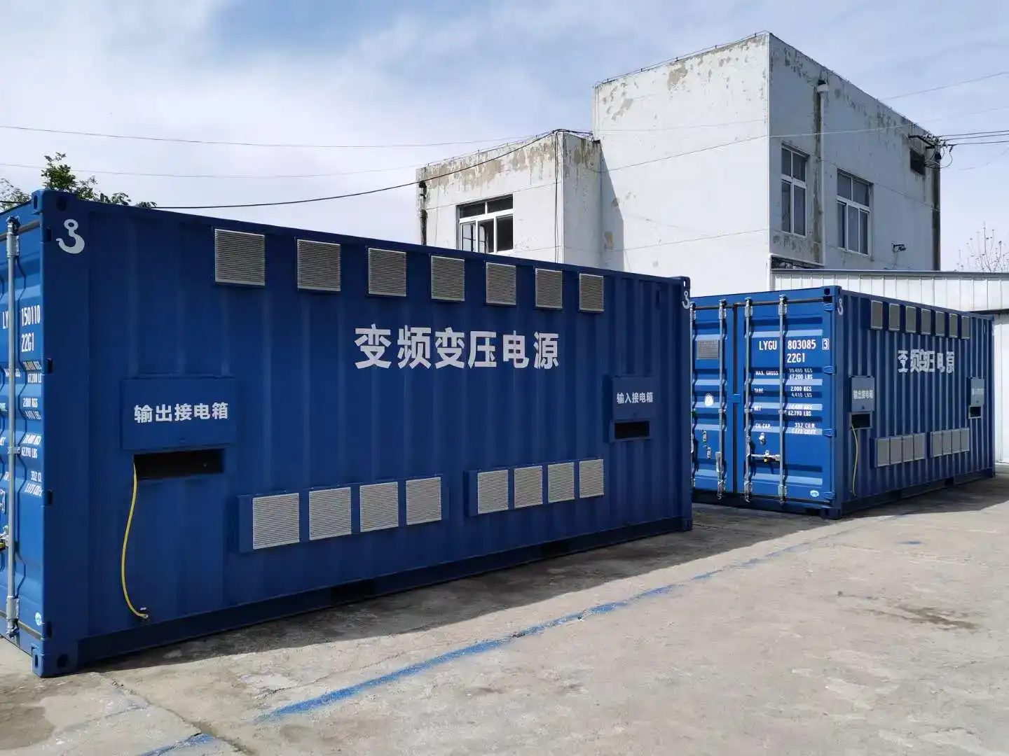
The main equipment included incoming ring-main switchgear, low-voltage outgoing switchgear, a 500 kVA dry-type isolation transformer, a movable weather-resistant enclosure, an electric chassis, berth-side connection boxes, flexible connection cable and ventilation equipment.
These ratings describe that particular engineering configuration. They are not universal limits or a standard SDACME mobile product specification.
The important point is the architecture:
EMSA guidance also recognizes an LV-OPS mobile architecture in which installed high-voltage infrastructure supplies a mobile low-voltage step-down berth unit.
The Mobile Package Is More Than a Transformer on Wheels
The equipment schedule for the 500 kVA configuration shows why a mobile shore power unit should be treated as an integrated electrical package.
The low-voltage outgoing section used a 630 A breaker arrangement with protection and metering.
The dry-type transformer was configured for:
- 6.6 kV to 440 V / 60 Hz; or
- 6 kV to 400 V / 50 Hz.
Cooling fans and transformer temperature monitoring were included in the configuration.
The transformer enclosure was specified as a movable weather-resistant housing, with an enclosure protection requirement of at least IP33 for that project.
These details matter because movement does not reduce the normal electrical duties imposed on the equipment.
The package still has to accommodate:
- continuous operating current;
- prospective fault current;
- transformer thermal loading;
- marine environmental exposure;
- repeated vibration;
- switching operations;
- 以及维修通道。.
Interface Design Determines Whether Mobility Is Practical
The most difficult part of repeated movement is often not moving the enclosure.
It is re-establishing every interface correctly.
Incoming Power
The unit must connect to the available shore-side source at the approved operating position.
Outgoing Vessel Supply
The low-voltage supply must reach the vessel connection arrangement without creating excessive temporary cabling or uncontrolled cable routes.
Protective Earth and Equipotential Bonding
The designed protective path has to be re-established before energization.
控制与沟通
Status, permissives, alarms and required communications must be restored at the new operating position.
Auxiliary Services
Ventilation, enclosure auxiliaries and other support functions may also depend on the operating position.
If these interfaces cannot be recreated consistently, the project may have a movable package without having a practical mobile operating system.
Real Connection Hardware Changes the Mobility Assessment
In the two-berth 500 kVA configuration, the equipment schedule did not stop at the transformer and switchgear.
The high-voltage shore-side interface included a 7.2 kV, 350 A connection arrangement.
The low-voltage side included a 0.44 kV connection box with multiple quick-connect interfaces, including 350 A and 250 A connections.
A 10 m flexible connection cable was also included together with the electric chassis.
A system that requires substantial temporary field wiring after every relocation loses much of the operating advantage that mobility was intended to provide.
Survey the Route Before Selecting the Chassis
The mechanical carrier should be one of the later decisions, not the first.
The route needs to be surveyed against the actual package.
Important inputs include:
- route width;
- turning radius;
- gradient;
- pavement or quay-surface capacity;
- wheel or axle loading;
- total package mass;
- centre of gravity;
- 排水;;
- overhead clearance;
- crane operating envelopes;
- cargo and road-traffic routes;
- stored equipment and emergency access.
The final stopping positions also need to be defined.
A mobile electrical package cannot simply be parked wherever physical space appears available.
The approved position must support stable parking, securing against unintended movement, connection reach, safe cable routing, ventilation airflow, operating access and maintenance space.
Selecting a trailer or chassis first and then trying to make the berth accept it reverses the engineering process.
Use Approved Operating Positions, Not an Undefined Movement Area
Repeated mobility becomes easier to control when the project defines specific operating positions.
For example, Position A and Position B can each have a documented set of electrical and mechanical interface conditions.
For every position, the engineering package can define:
- source voltage and frequency;
- available fault level;
- incoming connection;
- outgoing vessel connection;
- 接地装置;;
- cable route;
- communication interface;
- access requirements;
- parking and securing method;
- and permissible operating envelope.
This is more robust than assuming the mobile package can connect safely at any convenient point along the quay.
Electrical Conditions Must Be Checked at Every Approved Position
Two stopping positions can appear mechanically identical and still be electrically different.
The upstream network impedance may differ. Cable length may change. The connection interface may change. Earthing conditions may differ.
Protection coordination may therefore need to be confirmed against the actual approved source point.
This becomes particularly important when the unit can connect to more than one input configuration or provide more than one vessel supply condition.
Short-Circuit Duty Still Belongs to the Mobile-System Design
Mobility does not remove the need for fault-level verification.
The 500 kVA engineering configuration included a dedicated short-circuit calculation rather than relying only on equipment nameplate ratings.
The calculation used a 100 MVA source short-circuit basis, 6 kV / 6.6 kV incoming conditions, a 500 kVA isolation transformer 还有 6% transformer impedance.
Under the documented 6 kV / 0.4 kV case, the calculation produced approximately ≤9.622 kA on the 6 kV supply side 还有 ≤11.1 kA for the 0.4 kV vessel-side fault calculation.
These are project-specific calculation results, not generic mobile shore power ratings.
Their importance is methodological.
Switchgear, transformer, cables and connection equipment still need to be checked against the fault conditions associated with the approved operating positions.
Protection and Earthing Remain Part of the Complete Shore Connection System
IEC/IEEE 80005-3:2025 treats low-voltage shore connection as a complete system rather than a standalone transformer or outlet.
For its applicable LVSC range, the standard addresses shore-side connection systems, ship-to-shore interfaces, transformers, protection, control, monitoring, interlocking and power management.
That system boundary is particularly relevant to mobile arrangements.
A package can be mechanically secured and still be electrically unready.
Before energization, the project may need to confirm:
- protective-earth continuity;
- connector status;
- 断路状态;;
- valid operating mode;
- 电压和频率;;
- control permissives;
- communication availability where required.
The chassis itself should not be assumed to provide the designed protective-earth path.
Relocation Should Be Treated as a Defined Power-System State
A mobile shore power unit should not simply be driven away when the previous vessel has finished using it.
Relocation should have a defined sequence.
This does not mean the complete original commissioning programme must be repeated after every move.
The objective is to identify what changed during relocation and verify those interfaces before the next service.
What Should Be Checked After Each Move?
The post-relocation checklist should match the actual project architecture.
- Visual inspection for transport damage
- Correct operating position
- Mechanical securing
- Cable and connector condition
- Protective-earth continuity
- Correct incoming supply
- V电压和频率
- Phase sequence where relevant
- Switchgear state
- Communication status
- Local / remote control mode
- Interlock and permissive status
- Ventilation availability
- Alarm status
The required checks should be defined during engineering rather than improvised by the berth operator every time the package changes position.
The Layout Must Support Maintenance as Well as Movement
A mobile system is still an electrical plant.
Internal layout therefore needs to consider more than minimum external dimensions.
The reference 500 kVA arrangement was developed as a compact mobile package with dedicated areas for incoming equipment, transformer equipment and low-voltage outgoing equipment.
Moving the enclosure between berths does not eliminate the need to:
- access the transformer;
- operate switchgear;
- inspect cables;
- service ventilation;
- reach terminals;
- and maintain safe internal working access.
A package that can physically move but cannot be maintained efficiently can lose availability over its operating life.
Repeated Movement Creates Additional Maintenance Duties
Fixed electrical equipment mainly experiences stationary environmental and electrical stresses.
Mobile equipment adds another stress source: repeated mechanical movement.
This can affect:
- bolted connections;
- cable supports;
- terminal points;
- door hardware;
- ventilation components;
- instrument connections;
- sensors;
- plugs;
- and flexible cables.
The carrier itself also becomes part of the preventive-maintenance programme.
Depending on the movement arrangement, that can include wheels, brakes, steering, drive equipment, jacks, position sensors, securing devices and structural inspection.
Mobility Creates a Shared-Capacity Dependency
Sharing one package between several berths can reduce duplicated equipment.
It also creates a common dependency.
If the shared unit is unavailable because of transformer maintenance, switchgear fault, chassis problems, connector damage, a blocked movement route or scheduled inspection, every berth that depends on that package can lose access to the shared resource.
Transfer Time Is Part of the Capacity Study
A berth schedule does not contain only electrical load. It also contains time.
If Vessel A finishes shore power service at one berth and Vessel B requires the same mobile unit elsewhere, the practical transfer time includes:
- normal disconnection;
- 隔离;;
- cable recovery;
- movement authorization;
- travel;
- final positioning;
- securing;
- reconnection;
- verification;
- and energization preparation.
A short physical drive can therefore produce a much longer operational transfer window.
Projects with more complex simultaneous-load requirements should also evaluate the wider 多泊位岸电系统设计 rather than assuming one shared mobile package will be sufficient.
When Is Mobile Shore Power a Strong Architecture?
Mobility becomes attractive when several conditions align.
- There are multiple approved service positions.
- Their full shore power demand is largely non-simultaneous.
- A shared package can meet the required single-vessel load.
- The movement route is practical.
- The package can be positioned and secured consistently.
- Electrical interfaces can be connected repeatedly without extensive field work.
- Transfer time fits the berth operating schedule.
- Post-relocation verification can be completed predictably.
- Carrier maintenance does not create unacceptable availability risk.
When these conditions are met, mobility can reduce duplicated major equipment while preserving operational coverage.
When May Fixed or Independent Equipment Be Better?
A mobile system should not be selected simply because it sounds more flexible.
Fixed or independent equipment may be more suitable when:
- two or more berths regularly require shore power simultaneously;
- the movement route crosses critical cargo or vehicle operations;
- ground loading or turning geometry limits the carrier;
- repeated cable handling is difficult;
- repositioning requires long shutdown periods;
- electrical conditions vary substantially between locations;
- very high availability is required at every berth;
- or repeated reconnection introduces more work than equipment sharing saves.
Engineering Inputs Required Before Selecting a Mobile Architecture
A meaningful mobile shore power review should begin with project information rather than a product catalogue.
- 泊位布局
- Proposed operating positions
- Vessel types
- Vessel shore-power ratings
- Expected vessel schedule
- Simultaneous-demand scenarios
- 输入电压和频率
- Available short-circuit data
- Required vessel voltage and frequency
- Movement route
- Route width and turning constraints
- Surface and ground-loading limits
- Equipment mass limits
- Required relocation frequency
- Acceptable transfer time
- Cable connection and storage method
- Incoming and outgoing connector requirements
- Protective-earth and bonding arrangement
- 控制与通信要求
- Environmental conditions
- Parking and securing requirements
- Post-relocation acceptance checks
With these inputs, fixed, transportable and operationally mobile architectures can be compared on the same engineering basis.
常见问题解答
每个集装箱式岸上电力装置都是移动的吗?
No. Containerization describes equipment integration and enclosure format. Operational mobility requires a repeatable movement method, approved positions, suitable interfaces, securing and post-relocation verification.
一个移动式岸电装置可以供两个泊位使用吗?
Yes, when the vessel schedule allows sequential service and the electrical interfaces are designed for both positions. Two connection points do not increase the simultaneous capacity of the shared package.
移动设备是否需要配备频率转换器?
Not always. The required equipment depends on the shore supply and vessel requirement. A mobile package may contain transformation only, frequency conversion plus transformation, switchgear or another project-specific combination.
移动式岸电装置可以使用中压输入电源吗?
Yes. One 500 kVA engineering configuration used 6 kV / 50 Hz or 6.6 kV / 60 Hz input and supplied 400 V / 50 Hz or 440 V / 60 Hz low-voltage vessel service through a mobile transformer arrangement.
是否每次都需要重新启动设备才能进行搬迁?
Not necessarily. The project should identify which electrical and mechanical interfaces are disturbed by movement and define the post-relocation checks required before energization.
移动式岸上电力是否总是比固定式电力更便宜?
No. A shared mobile package can reduce duplicated electrical equipment, but it adds carrier cost, route requirements, repeated connection work, transfer time and mechanical maintenance. The comparison needs to include the complete operating lifecycle.
技术参考
IEC/IEEE 80005-3:2025 — Utility connections in port — Part 3: Low-voltage shore connection systems — General requirements. The current edition covers applicable low-voltage shore connection design, installation and testing, including shore-side connection systems, shore-to-ship interfaces, transformers, conversion equipment, protection, control, monitoring and interlocking. IEC publication
European Maritime Safety Agency — Shore-Side Electricity: Guidance to Port Authorities and Administrations. EMSA guidance addresses project decision-making, infrastructure development, responsibilities and operational controls for shore-side electricity. EMSA guidance
Check the Operating Case Before Selecting the Chassis
Send the berth layout, movement route, vessel load and voltage/frequency requirements, available grid and fault data, simultaneous-demand case, proposed connection interfaces and allowable transfer time. These inputs can be used to review whether the project is better suited to a fixed, transportable or operationally mobile shore power architecture.
Send Your Mobile Shore Power Requirements