
岸上电力工程指南
如何为集装箱式岸电系统选择 HVAC 规格
Containerized shore power HVAC sizing should start with the heat that must actually be removed from the conditioned enclosure under the project design condition—not with the converter kVA rating alone.
A shore power container is not a single heat source. Depending on the architecture, the conditioned enclosure may contain frequency-converter power cells, transformers, reactors, switchgear, control power supplies, UPS equipment, PLC and HMI hardware, lighting and other auxiliaries.
The enclosure itself is also exposed to outdoor temperature, solar radiation, humidity, dust and the marine environment.
A 630 kVA system therefore does not have a 630 kW cooling load, and two 630 kVA shore power packages can require very different HVAC arrangements.
“How many air conditioners does a 630 kVA converter need?”
那就是:
“How much heat enters this thermal zone at the worst credible operating condition, how will that heat reach the cooling system, and what operating condition must remain possible if one cooling unit fails?”
Why Converter kVA Is Not the Cooling Duty
Electrical output and thermal loss describe different things.
A frequency converter may transfer hundreds of kilovolt-amperes to a vessel, but only the converter losses become heat inside the equipment space. The same principle applies to transformers, reactors and switchgear: their full electrical rating is not released as heat.
For preliminary engineering, converter efficiency can help estimate loss if the efficiency is known at the relevant operating point.
Where efficiency is known:
This remains an initial estimate. Final cooling design should preferably use equipment loss data for the actual operating configuration.
A second question must then be answered:
If a transformer is installed inside the conditioned enclosure, its heat may belong in that HVAC calculation. If it is installed in a separate ventilated compartment and rejects heat directly outdoors, assigning all of its losses again to the converter-room HVAC would overstate the required duty.
Define the Thermal Boundary Before Calculating Anything
A containerized shore power package can contain several physically different thermal zones:
- converter room;
- transformer compartment;
- medium-voltage switchgear section;
- low-voltage switchgear section;
- auxiliary or control compartment;
- separately ventilated equipment.
Each zone may reject heat differently. The calculation should therefore identify which equipment losses enter the conditioned room and which are rejected somewhere else.
A useful distinction is:
- Equipment-level cooling moves heat away from components.
- Enclosure-level cooling removes that heat from the conditioned enclosure and ultimately rejects it outdoors.
A cabinet fan can move heat away from an IGBT module and reduce local component temperature, but if the hot air is discharged into the container, the enclosure HVAC still has to remove that heat.
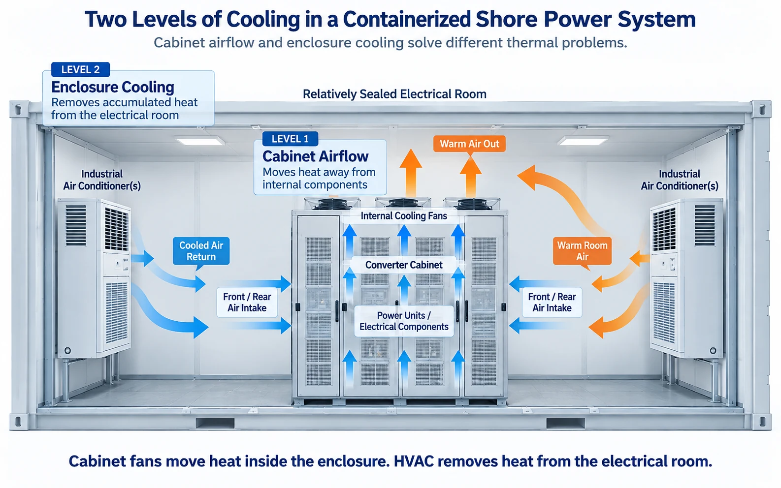
For the wider relationship between cabinet airflow and enclosure heat rejection, see our 岸电系统冷却和VHAC设计 指南。.
From Electrical Loss Data to HVAC Selection
Define the Design Operating Point
Do not start with only the largest number printed on the equipment nameplate.
Define the expected operating condition:
- expected vessel load;
- maximum continuous electrical load;
- 输入和输出电压;;
- frequency operating mode;
- converter operating point;
- simultaneous auxiliary loads.
A shore power converter operating near full load for long periods can have a different thermal profile from the same converter used mainly at partial load.
Prepare an Equipment Loss Schedule
List every meaningful heat-producing device within each thermal zone.
| Equipment or Heat Source | Required Information |
|---|---|
| Frequency converter | Losses at relevant operating load and configuration |
| 变压器 | No-load and load losses plus installation location |
| Reactor | Load-dependent losses and thermal location |
| Switchgear | Internal electrical losses where significant |
| Control transformer | Continuous auxiliary losses |
| UPS / DC supply | Conversion and charging losses |
| PLC / HMI / controls | Continuous auxiliary heat |
| Fans | Motor losses entering the conditioned space |
| Lighting | Installed or expected operating load |
Allocate Each Loss to the Correct Thermal Zone
This is where an apparently precise calculation can become misleading.
Consider a package with converter cabinets inside an air-conditioned room, a transformer in a separate compartment and an auxiliary cabinet inside the conditioned zone.
Converter and auxiliary losses may enter the conditioned room directly. Transformer losses may not.
If the transformer compartment shares return air with the converter room, however, some or all of its heat may again become part of the HVAC duty.
Add Enclosure and Environmental Heat Gain
The enclosure itself exchanges heat with the outdoor environment.
A simplified conductive heat-transfer relationship can be expressed as:
where:
- U = overall heat-transfer coefficient;
- A = effective enclosure surface area;
- ΔT = indoor-to-outdoor temperature difference.
The direction of heat flow matters. When the outdoor temperature exceeds the required internal temperature, enclosure transmission adds to the cooling load. Under cooler conditions, the enclosure may naturally dissipate part of the internally generated heat.
Solar radiation can add another significant load, especially for outdoor containers exposed directly to the sun.
Add Ventilation, Leakage and Moisture Effects Where Applicable
A shore power enclosure is not always completely sealed.
Outside air may enter through:
- deliberate fresh-air ventilation;
- equipment openings;
- cable penetrations;
- imperfect sealing;
- doors opened during maintenance;
- pressure differences caused by fans.
Outside air can introduce both sensible heat and moisture. This can become important in hot and humid coastal environments.
Thermal management is therefore an enclosure-system decision, not merely an air-conditioner selection exercise.
Determine the Design Cooling Duty
The sign and relevance of each term depend on the project.
A useful design record should separately show:
- calculated internal losses;
- enclosure heat transfer;
- solar and environmental heat gains;
- ventilation or infiltration loads;
- identified uncertainty;
- required design reserve.
Select HVAC at the Actual Site Condition
Required cooling duty and catalogue cooling capacity are not automatically comparable.
Cooling-unit performance depends on the conditions at which it is rated. The same unit may provide different usable cooling output at different ambient and internal temperatures.
The design basis should therefore identify:
- maximum outdoor dry-bulb temperature;
- required internal temperature;
- 湿度;;
- solar exposure;
- dust and contamination;
- salt-laden atmosphere;
- altitude where relevant.
The selected HVAC capacity should then be checked against the manufacturer's performance data at those project conditions.
For marine environmental measures, see our 岸电腐蚀和防盐雾保护 文章.
Check the One-Unit-Out Condition
Only after the normal cooling duty has been established does redundancy become meaningful.
If one HVAC unit becomes unavailable, the project has to define what the shore power system is expected to do.
Do Not Hide Margin Inside an Arbitrary Oversizing Factor
Engineering margin is necessary because equipment does not operate forever under clean catalogue conditions.
Cooling performance can be affected by:
- filter loading;
- fouling;
- airflow resistance;
- partial recirculation;
- equipment ageing;
- uncertainty in electrical losses;
- solar-load variation;
- installation tolerances.
These conditions justify reserve, but the reason for that reserve should remain visible.
A generic rule such as “multiply the cooling load by 1.3” is not automatically a better design unless the factor has a defined engineering basis.
Airflow Is Part of the Thermal Design
Cooling capacity answers one question:
Airflow answers another:
Poor airflow can produce local thermal failure even when the total installed HVAC capacity appears adequate.
Important areas include:
- converter cabinet air inlets;
- cabinet exhausts;
- hot-air return paths;
- partitions;
- cable trenches;
- raised floors;
- equipment clearances;
- wall-mounted HVAC units;
- condenser intake and discharge locations.
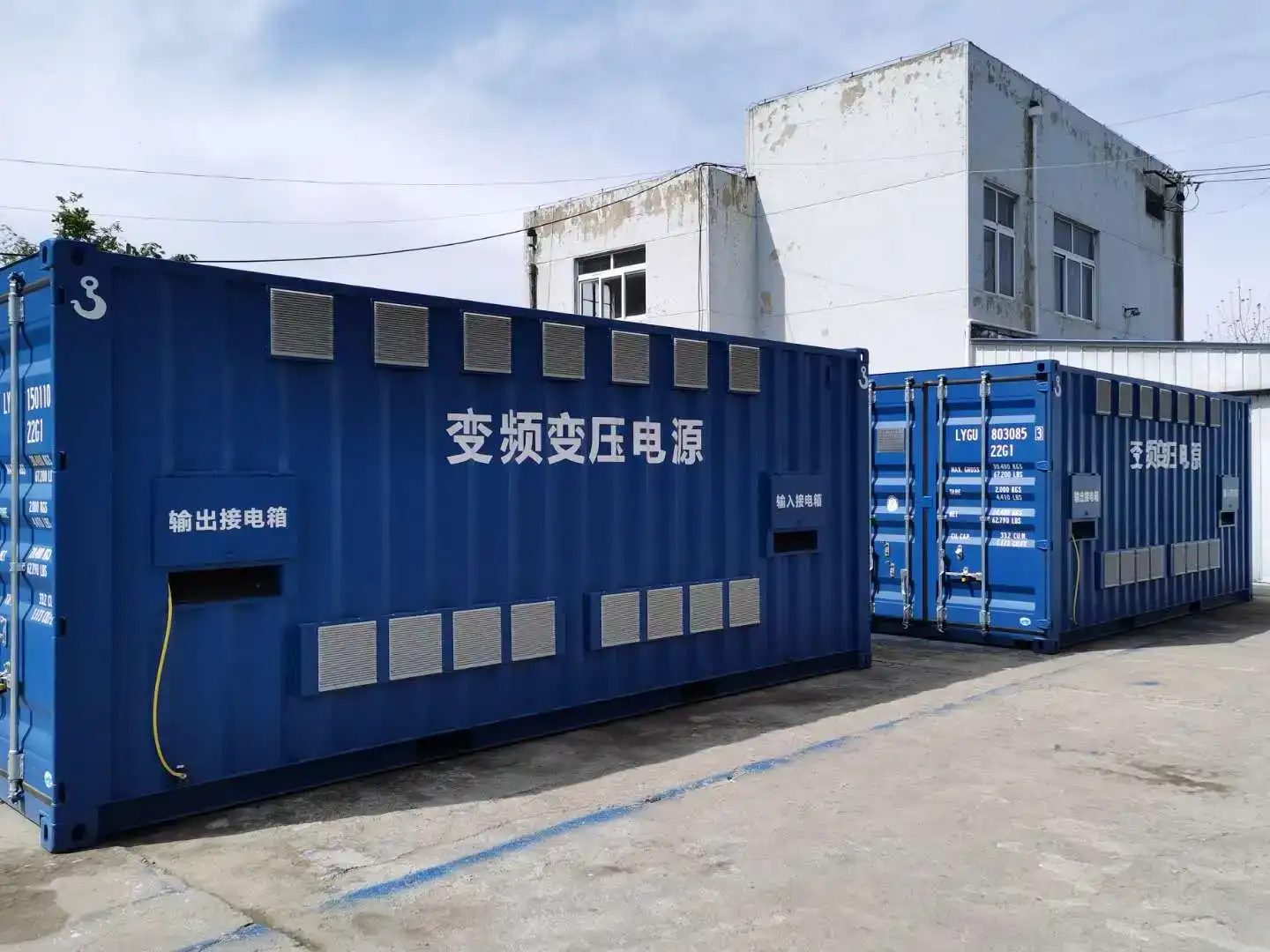
One engineering configuration used relatively short and wide airflow paths through the converter power-unit area, with air entry around the cabinet and high-volume fans at the upper section.
The lesson is not that every project should copy that cabinet geometry. It is that equipment airflow and enclosure heat rejection must be engineered together.
Why Adequate Cooling Capacity Can Still Overheat in Service
Hot-Air Recirculation
If hot discharge air returns directly to the equipment intake, the effective inlet temperature increases. The room may still have enough theoretical refrigeration capacity while the converter receives air that is too warm.
Blocked or Restricted Airflow
Filters, cable routing, temporary materials or later installation changes can restrict airflow after commissioning. The calculated heat load has not changed, but the heat-transfer path has.
Poor Sensor Location
One room-temperature sensor may not represent every thermal zone. A normal reading near the return-air path can exist at the same time as a hotter converter inlet or upper cabinet zone.
Condenser Recirculation
Outdoor condenser airflow also matters. One condenser should not discharge heated air directly into the intake of another cooling unit.
Loss of a Common Auxiliary Supply
Several cooling devices can be mechanically independent while still depending on the same electrical feeder or control source.
Standby Humidity
When the converter operates, its losses naturally warm the enclosure. When it is idle, that heat disappears. In a humid environment, the dominant problem may then change from overheating to condensation control.
N+1 Cooling Is a Performance Requirement, Not an Equipment Count
“N+1 HVAC” is incomplete unless the required system condition after one cooling-unit failure has been defined.
Full-Output Continuity
One HVAC unit is unavailable, but the remaining equipment must keep the enclosure within the approved thermal limits while the shore power system remains at full specified output.
Derated Operation
Remaining cooling capacity can support continued operation only after electrical output is reduced to a defined level.
Time-Limited Operation
Thermal inertia allows continued operation for a defined period, followed by controlled shutdown if cooling is not restored.
Both sides of the comparison must use the same project ambient condition and the same defined electrical load.
Installing an additional air conditioner does not, by itself, demonstrate useful N+1 performance.
Common-Mode Failure Can Defeat Cooling Redundancy
Redundancy needs to be checked across the complete cooling chain.
Four air-conditioning units supplied from one auxiliary feeder may appear mechanically redundant, but the feeder can remain a single point of failure.
同样的原理也适用于:
- common control power;
- shared HVAC controller;
- common breaker;
- shared fan supply;
- common communication dependency;
- shared condenser or airflow constraints.
In one shore power engineering configuration, the converter cooling fans were provided with two alternative power sources. That design was project-specific, but it illustrates the underlying principle:
Coordinate Cooling Faults With the Operating State
HVAC and fan faults are part of the electrical operating system, not merely building-service alarms.
The control system may need to monitor:
- HVAC running status;
- HVAC fault;
- converter cooling fan status;
- transformer fan status;
- enclosure temperature;
- transformer temperature;
- auxiliary cooling power;
- filter condition where monitored;
- condensate alarm where relevant.
The required response then depends on the remaining thermal capability.
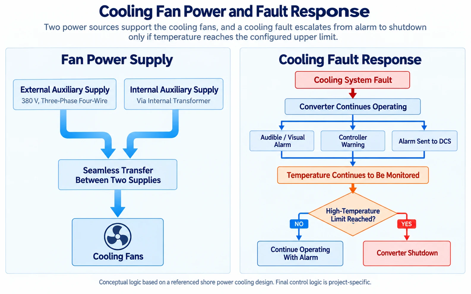
In one reference configuration, cooling failure generated local and remote alarms while the converter could initially remain in service. If the condition was not corrected and temperature reached the configured upper limit, the converter stopped.
The important engineering point is that a cooling fault and an overtemperature trip are not necessarily the same event.
Project Evidence: What a 630 kVA Configuration Actually Tells Us
One 630 kVA shore power configuration used four customized 5P industrial air-conditioning units for enclosure cooling.
That is useful engineering evidence, but it does not create a general relationship such as:
The useful lesson is that HVAC quantity only becomes meaningful after the project has already established:
- equipment arrangement;
- internal heat sources;
- thermal-zone boundaries;
- enclosure configuration;
- cooling method;
- project environmental condition.
Another 630 kVA package may place the transformer outside the conditioned enclosure and therefore present a lower internal heat load.
A different 630 kVA project may operate in a hotter environment, experience greater solar gain or require full electrical output after one HVAC unit fails, resulting in a higher installed cooling requirement.
The electrical rating stayed the same.
The thermal design did not.
What the 4 × 5P Configuration Does Not Prove
The project example does not by itself prove:
- the heat loss of every 630 kVA converter;
- a universal design ambient temperature;
- a universal redundancy requirement;
- a universal 5P cooling capacity;
- a universal number of HVAC units;
- that another port should use the same configuration.
A technically credible proposal should distinguish between a proven project configuration and a reusable engineering calculation method.
Thermal Design Should Produce Acceptance Evidence
HVAC engineering is not complete when the cooling equipment is ordered.
The calculation should produce documentation that can later be checked during FAT and commissioning.
| 证据 | What It Verifies |
|---|---|
| Approved equipment loss schedule | Heat-generation basis |
| Thermal-zone drawing | Which losses belong to each cooling boundary |
| Airflow drawing | Supply, return and equipment airflow paths |
| HVAC performance curve | Available cooling capacity at project conditions |
| Auxiliary-power diagram | Common-mode cooling failure boundaries |
| Temperature sensor schedule | Which thermal conditions are actually monitored |
| Cause-and-effect matrix | Alarm, derating and shutdown behavior |
| FAT thermal record | Actual temperature response under the test load |
| Commissioning record | Installed airflow, controls and thermal response |
This evidence chain is more useful than a specification that simply says “industrial air conditioning, N+1.”
Verify Cooling During FAT
FAT should verify both the physical cooling arrangement and the control response.
Relevant checks can include:
- fan rotation and airflow direction;
- fan running status;
- HVAC start and stop;
- staged operation;
- duty/standby changeover where provided;
- HVAC fault;
- fan fault;
- high-temperature alarm;
- temperature protection;
- control-system indication;
- defined derating or shutdown functions.
A sustained load test provides stronger thermal evidence than brief energization because transformers, reactors, cabinets and the enclosure itself require time to approach a meaningful thermal condition.
Useful test data include:
- electrical load;
- 环境温度;;
- internal enclosure temperature;
- converter inlet-air temperature where monitored;
- transformer or reactor temperature where applicable;
- active cooling units;
- fan states;
- elapsed operating time.
For the wider outdoor power-package arrangement, see our 集装箱式岸上供电系统 页面.
A Cool Factory Test Does Not Prove a Hot-Site Design
Suppose the project thermal design condition is a high outdoor temperature, but FAT is performed in a much cooler factory.
The converter reaches full load and every recorded temperature remains acceptable.
That is useful evidence.
It is not, by itself, proof that the same enclosure will remain inside its thermal limits at the maximum project ambient.
Two important conditions have changed:
- the heat exchange through the enclosure surface;
- the cooling performance available from the HVAC equipment.
The stronger engineering assessment combines:
What Should Be Recorded at Thermal Stabilization?
A useful acceptance record should not say only:
The operating conditions need to be recorded so that the result can be interpreted later.
Consider recording:
- actual electrical load or load percentage;
- input/output operating mode;
- 环境温度;;
- internal enclosure temperature;
- representative cabinet inlet temperature;
- transformer temperature where applicable;
- operating HVAC units;
- disabled HVAC units during redundancy testing;
- 粉丝状态;;
- time from load application to stabilized reading;
- alarm state;
- derating or trip state.
A temperature value without the operating condition has limited engineering meaning.
For example, an enclosure temperature of 35°C can describe an excellent result at high load and high ambient—or a weak result at low load in a cool factory.
Context turns the measurement into evidence.
Common HVAC Sizing Errors
Information Needed Before HVAC Sizing
For a containerized shore power project, thermal inputs are more useful than the converter rating alone.
Electrical and Equipment Data
- converter rating;
- expected load profile;
- converter loss data;
- 变压器损耗;;
- transformer installation location;
- reactor losses;
- switchgear losses where relevant;
- UPS and auxiliary loads.
Enclosure Data
- container dimensions;
- equipment arrangement;
- thermal-zone boundaries;
- wall and roof construction;
- insulation;
- openings;
- cable penetrations;
- planned ventilation.
Environmental Data
- maximum outdoor temperature;
- minimum outdoor temperature where relevant;
- 湿度;;
- solar exposure;
- altitude;
- 灰尘;;
- salt-fog conditions.
操作要求
- permissible internal temperature;
- equipment inlet-air limits;
- standby environmental requirements;
- allowable reduced-load operation;
- required output after one HVAC failure;
- allowable time before shutdown.
HVAC Data
- rated cooling capacity;
- performance curve versus ambient temperature;
- air volume;
- filtration;
- condenser arrangement;
- auxiliary power;
- alarm and control interface.
Verification Requirements
- FAT load;
- FAT duration;
- required sensor locations;
- temperature acceptance criteria;
- one-unit-out test requirements;
- alarm and shutdown tests;
- commissioning verification.
常见问题解答
是否可以通过转换器的效率来估算HVAC的容量?
是的,用于初步工程。 V经验证的效率和运行负荷可以提供早期转换器损耗的估算值。最终的尺寸设计仍应包括其他设备损耗、箱体热传递、环境热量增加以及实际的热区布置。.
每个集装箱式岸上电力系统都需要空调吗?
不。根据设备和环境的不同,该封装可能采用强制通风、空调、换热器、闭环冷却或其他工程化的热管理方法。.
630 kVA 的额定功率是否决定了 HVAC 的容量?
不正确。电气规格并不定义内部损耗、外壳热量增加、现场环境条件或冗余目标。.
4 台 5P 空调机组是否是 630 kVA 系统的标准配置?
不。在某一项目配置中使用了四台定制的 5P 单元。该设备数量具体取决于项目的机箱和散热方案,不应被视为通用的尺寸计算规则。.
N+1 HVAC到底是什么意思?
这意味着在特定故障情况下具备额外的冷却能力。剩余设备仍需根据所需的故障后电气负载和项目环境条件进行检查。.
如果箱体温度仍然正常,是否可以忽略一个VHAC故障?
Not automatically. Temperature may rise slowly because of thermal inertia. The project should define the required alarm, monitoring, derating and shutdown response while the remaining cooling capability is assessed.
Should HVAC operate when the converter is idle?
Possibly. Standby heating, ventilation or dehumidification may still be required where humidity or condensation could move outside acceptable equipment conditions.
Does a successful full-load FAT prove HVAC capacity at site?
Not always. If FAT ambient conditions are less severe than the project design condition, the test should be combined with verified heat losses, enclosure thermal calculations and HVAC performance data at the project ambient.
What thermal data should be recorded during FAT?
Record the electrical load, ambient temperature, internal temperatures, relevant equipment temperatures, active HVAC units, fan status and sufficient operating time to show a meaningful thermal condition.
技术参考
- IEC/IEEE 80005-1:2019 — High Voltage Shore Connection Systems , including its published amendments.
- IEC/IEEE 80005-3:2025 — Low-Voltage Shore Connection Systems .
- Rittal technical guidance on enclosure thermal management and cooling calculation .
- Schneider Electric enclosure cooling-unit performance guidance .
Scope note: shore-connection standards define the wider electrical system framework. They do not establish a universal rule such as “X kVA requires Y tons of HVAC.” Thermal sizing still depends on the actual equipment losses, enclosure arrangement, environmental conditions and required post-failure operation.
Send the Thermal Design Inputs, Not Only the Converter Rating
Send the equipment loss schedule, enclosure layout, thermal-zone arrangement, outdoor design conditions, required internal temperature and cooling-redundancy target. SDACME can review the heat-rejection boundary, cooling duty, airflow arrangement, HVAC performance, auxiliary-power dependency, alarm response and thermal verification requirements as part of the shore power system engineering review.
Send Thermal Design Inputs