
岸上电力工程指南
岸上电力远程监测、状态和控制点列表
岸电点列表应规定操作员、控制系统和维护团队在整个运行过程中需要测量、观察、确认、诊断和控制的信息。.
它不应该通过从开关柜、变流器、继电器、仪表、变压器控制器或PLC导出所有可用的寄存器来创建。.
一份有用的岸上电源点列表连接了四件事: 物理设备、操作决策、向操作员提供的信息以及系统预期的响应。.
出于这个原因,遥测数据、状态指示、报警、事件以及远程命令应该保持清晰的可辨别性。每个重要点还需要有一个明确的源头、工程意义、数据质量行为和验证方法。.
对于命令,定义更进一步:在远程操作变得有意义之前,操作权限、所需模式、允许性、锁止和完成反馈必须明确无误。.
为什么海岸电能点列表不仅仅是一个标签数据库
现代的海岸供电系统可以暴露出数以千计的内部变量。.
高压开关柜可以报告电气测量值、断路器位置等信息。 继电器指示和设备状态。变频器可以提供 运行值、模式、负载情况以及内部故障信息。变压器可以 提供温度和冷却信息。连接箱可以报告连接情况 准备性和接口条件。电缆管理设备可以提供 运动、超载或位置信息。.
因此,数据可用性很少是主要问题。.
一个监控系统可以包含数百个标签,但仍然无法回答基本的运行问题:
- 系统是否已准备好启动运行?
- 哪些许可协议缺失了?
- 断路器真的关闭了吗?
- 显示的数值是实时数据还是历史数据?
- 哪台设备引发了第一个故障?
- 通信失败后,目前的操作还能继续进行吗?
如果点云列表无法回答这些问题,那么该系统可能在数据方面非常丰富,但在操作方面却非常薄弱。.
这就是为什么要根据操作顺序和控制理念制定点阵表,而不是根据设备手册中提供的地址数量。.
岸电信号实际上来自哪里
岸电SCADA屏幕只是最终的呈现层。.
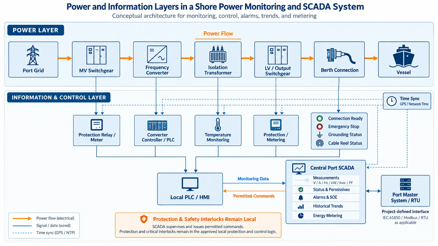
其背后是一系列设备、传感器、保护装置、控制器和通信接口。.
每个设备层都会生成不同的信息类型。.
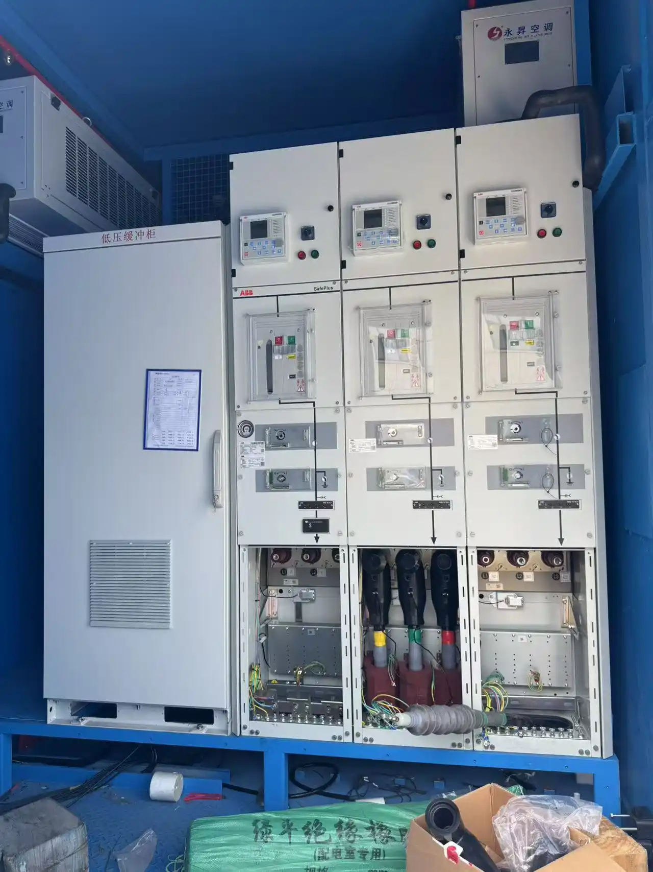
高压开关柜可以提供电压、电流、频率、有效功率和无功功率、功率因数、能量以及断路器位置信息。.
该转换器可提供输入和输出的电气值、工作模式、负载状态、待机/运行状态和内部报警信息。.
该变压器可能提供温度和冷却系统信息。.
连接盒可能会报告连接是否已准备就绪、接地条件是否已建立,或者是否存在紧急断开连接的状况。.
电缆管理设备可能会报告支付、检索、移动、过载或扭矩情况。.
在与项目合作伙伴共同开发的某项岸上供电项目配置中,这些设备组被集成到一个远程监控系统中,其中现场信息被传输至控制层,而批准的远程命令则被返回到选定的设备上。.
这是一个重要的区别:
这些点的背后更深层次的物理层在我们的文章中进行了描述。 岸电系统架构与组件 页面.
独立化的遥测、状态、报警、事件和命令语义
第一类分类应该描述点到底意味着什么。.
| 点类型 | 工程意义 | 典型的海岸动力发电实例 |
|---|---|---|
| 遥测 | 一个量化的或计算出的值 | V电压、电流、频率、有效功率、无功功率、能量、变压器温度 |
| 状态 | 设备的当前状态或接口 | 断路器开启/关闭,转换器准备就绪,本地/远程模式,连接准备就绪,电缆卷筒位置 |
| 警报 | 一种需要意识或反应的异常情况 | High temperature, converter fault, communication failure, cable-reel overload |
| Event / Trip indication | A significant change or protective action requiring sequence reconstruction | Protection operation, overtemperature trip, breaker trip |
| Command | An authorized request for equipment action | Breaker open/close, converter start/stop/reset, approved sequence command |
This separation is not just about terminology.
Consider transformer temperature.
78 °C is a telemetry value. Transformer High Temperature is an alarm. Transformer Overtemperature Trip is a protection or event indication.
They may originate from related equipment, but they represent different operator meanings.
The same applies to breakers.
Breaker Closed is feedback. Breaker Close is a command.
A displayed closed-state point does not automatically mean that remote closing is permitted.

Power-system information models follow the same broader principle of keeping status information, measured information and controls semantically distinct. IEC 61850-7-3 defines separate common data classes for these information types.
The objective is not to force every shore power project into one protocol. The objective is to preserve clear engineering meaning.
Build the Point List From the Operating Sequence
The most reliable way to define monitoring points is to begin with the operating process.
At each stage, ask:
During preparation, the operator may need to confirm that the correct operating mode has been selected and that no maintenance or blocking condition is active.
During connection, interface conditions become more important: connection readiness, cable position, earthing condition, pilot or connection status, and the expected switchgear positions.
Before energization, the operator may need confirmation that the required permissives and interlocks are satisfied.
During normal operation, the information priority changes to electrical quality, output voltage and frequency, vessel load, transformer temperature, converter loading and active alarms.
After a trip, live operating values may become less important than first-out indication, event order, protection operation and the states immediately before and after the fault.
This approach prevents a common design mistake: collecting a large number of signals that nobody uses while omitting the one point required to explain why a start sequence is blocked.
Example Shore Power Point Families by Equipment
The final point list depends on the actual project architecture and owner requirements. However, project experience provides a useful way to understand how point families can be organized.
| 设备 | 遥测 | 状态 | Alarm / Event | Possible remote command |
|---|---|---|---|---|
| HV switchgear | V, A, Hz, P, Q, PF, energy | Breaker open/closed, local/remote, earthing-switch state | Overcurrent, undervoltage, protection operation, breaker trip | Open, close, approved sequence control |
| Shore power converter | V, A, P, Q, loading | Ready, running, stopped, selected mode | Phase loss, imbalance, reverse power, converter fault | Start, stop, reset |
| 变压器 | 温度 | Cooling / fan state | High temperature, overtemperature trip, cooling fault | Normally project-dependent |
| Connection box | Project-dependent | Connection ready, earthing, energized state | Door open, interface fault, emergency-disconnect indication | Project-dependent |
| Cable-management system | Project-dependent | Payout, retrieval, position / movement | Overload, excessive torque, equipment fault | Local or remote depending on risk assessment |
In one project configuration developed with project partners, the monitoring structure included these same underlying point families: electrical telemetry from high-voltage switchgear and the shore power source, transformer temperature, connection-box readiness and earthing indications, cable-reel movement signals, breaker commands and converter start/stop/reset functions.
The table above should therefore be treated as an engineering example, not as a universal template.
A 10 kV converter-based shore connection, a low-voltage system and a mobile shore power package may require different point structures.
Why More Points Can Make the System Worse
A large point count can look impressive during specification development.
It can also make the monitoring system harder to operate.
Every additional point can create additional work in PLC or gateway configuration, SCADA database engineering, screen design, alarm management, FAT, commissioning, documentation and long-term maintenance.
If the point does not support an operator decision, maintenance decision, billing function, protection awareness or diagnostic task, its value should be questioned.
This does not mean that systems should be artificially simplified.
A point list that is too small creates a different risk.
A missing permissive indication can leave operators unable to explain why energization is blocked.
Missing command feedback can make an unsuccessful operation appear successful.
Missing event information can make a trip difficult to reconstruct.
Why Status and Alarm Design Affects Operator Decisions
Status and alarm lists should be designed around different operator questions.
A status point answers: What state is the equipment in now?
An alarm answers: What abnormal condition requires attention?
A trip or event answers: What significant change or protective action occurred?
Consider a transformer cooling system.
Fan Running is a status. Fan Fault is an alarm. Transformer High Temperature is another alarm. Transformer Overtemperature Trip is a protection event.
If all of these are reduced to a single generic transformer alarm, the operator loses the sequence and meaning required for diagnosis.
The same principle applies to connection equipment.
Connection Ready is not the same as Connection Fault. Cable Reel Moving is not the same as Cable Reel Overload. Breaker Open is not the same as Breaker Tripped.
The point list should therefore preserve the difference between normal state, abnormal condition and protective action.
Alarm Detail Should Match Operator Responsibility
Not every equipment alarm needs to be sent to every control room.
A converter may generate dozens or hundreds of internal diagnostic codes. Many are useful to commissioning or maintenance engineers but provide little value to a remote port operator.
The remote system may therefore require a layered approach.
At the supervisory level, operators may need a summary such as Converter Fault.
At the local equipment or maintenance level, the engineer may need more detailed information such as DC-link fault, phase loss, cooling fault, internal power-cell fault or control-power failure.
The appropriate depth depends on who is expected to respond.
A good point list therefore considers not only what information is available, but also who receives it and what they are expected to do with it.
Remote Commands Need Authority, Mode, Permissives and Feedback
Remote command points require a different level of engineering discipline.
A writable communication address is not enough.
| Command question | What must be clear |
|---|---|
| 权威 | Who is allowed to issue the command? |
| 控制模式 | Must the system be in remote mode? |
| Permissives | Which operating conditions must already be valid? |
| 锁扣 | Which local electrical or mechanical interlocks remain active? |
| 接受 | Was the request received? |
| Execution | Did the equipment start acting? |
| 完成反馈 | Did the equipment reach the required final state? |
| Timeout / failure | What happens if the action is not completed? |
In project configurations, remote functions can include high-voltage breaker open/close and approved sequence-control functions together with shore power source start, stop and reset commands.
Those examples demonstrate that remote control can be part of a shore power architecture.
They do not mean every possible function should be remotely available.
我们的 岸上供电PLC和HMI控制 article explains how control modes, permissives, interlocks and operating sequences are represented to the operator.
Command Sent Is Not Action Completed
If the SCADA system only knows that the command was sent, it cannot prove that the required equipment state was reached.
This distinction becomes especially important when the final action depends on mechanical movement, auxiliary power or several local interlocks.
The point list should therefore include completion feedback and failed-operation behavior as part of the command definition.
Local Control and Remote Control Are Different Operating Responsibilities
Some equipment can be monitored remotely while still being operated locally.
This is particularly relevant for equipment involving movement close to personnel, cable handling or maintenance access.
A control-room operator may need to see cable reel position, movement state, overload condition and fault status.
That does not automatically mean that payout or retrieval should always be remotely enabled.
The final arrangement depends on equipment design, personnel exposure, visibility, owner operating procedures and project risk assessment.
A Point Definition Needs More Than a Tag Name
A mature point schedule normally contains more than Tag Name + PLC Address.
| Field | Engineering purpose |
|---|---|
| Point / tag name | Unique identity |
| 点类型 | Telemetry, status, alarm, event or command |
| Source device | Identifies the physical or logical source |
| Engineering unit | V, A, Hz, kW, kWh, °C, etc. |
| Scaling / resolution | Defines how raw data becomes engineering data |
| State meaning | Defines binary or enumerated states |
| Normal range | Supports operator interpretation |
| Data quality | Valid, stale, invalid or unavailable |
| Timestamp source | Supports event sequence reconstruction |
| Alarm priority / delay | Links the condition to operator response |
| 权威 | Defines who may control |
| Required mode | Local, remote, maintenance or another state |
| Permissive / interlock reference | Defines operating constraints |
| 完成反馈 | Proves equipment response |
| Timeout behavior | Defines unsuccessful command handling |
| 通信中断响应 | Defines behavior when supervision is lost |
| Verification result | Links the point to FAT / commissioning evidence |
The communication register map can define how information is transported. The point list defines what the information means.
These should not be confused.
A Modbus register address may tell the system where to read a value. It does not by itself explain whether the value is operational telemetry, maintenance information, a protection event, a stale value or a command with safety implications.
Data Quality Is Part of the Point Definition
The operator should know when a value is no longer trustworthy.
Suppose the last valid transformer temperature was 78 °C.
Communication is then lost.
If the SCADA display continues to show 78 °C with no indication that
the information is stale, an old value can be mistaken for a live measurement.
Replacing the value with zero is not necessarily better. Zero can itself be a legitimate value for many process variables.
The point definition should therefore specify how unavailable or stale data are represented.
Relevant considerations include quality indication, update behavior, last-valid-value handling, invalid-value display, communication-loss alarm and recovery behavior.
Time Synchronization Matters Because Faults Have an Order
Shore power trips often involve several devices.
A sequence may include relay pickup, protection trip, breaker opening, converter stop, PLC status change and SCADA alarm.
If the relay, converter, PLC and SCADA use different clocks, all individual records may be valid while the combined sequence is wrong.
The operator may know which events occurred but still be unable to determine which occurred first.
That is why timestamp source and time synchronization should be considered during point-list engineering rather than only after commissioning problems appear.
From Live Monitoring to Operational Evidence
A point does not stop being useful when the live screen changes.
Many monitoring points also become part of event logs, alarm history, trends, operating records, fault reconstruction and maintenance review.
Shore power monitoring systems can retain operating history, protection states, trends and event records rather than only showing instantaneous values.
This changes how a point should be evaluated.
A transformer temperature point may support real-time supervision, but its historical trend may also show whether cooling performance is degrading.
A breaker-state point may support normal operation, while its timestamp can help reconstruct a trip.
A converter alarm may be acknowledged within seconds, but its stored event record may later be needed to understand a repeated operating problem.
The point list is therefore also part of the project's operational evidence structure.
First-Out Information Is Often More Valuable Than More Alarms
During a complex trip, many alarms can appear within milliseconds or seconds.
The operator may see protection operation, converter stop, breaker open, undervoltage, communication disturbance and auxiliary alarms.
If every alarm is presented without sequence context, the screen can show the consequences of a fault more prominently than the initiating condition.
Where technically available, event records and timestamps should help distinguish:
This is why trip analysis requires more than a long alarm list. It requires event meaning and time context.
Keep Protection and Emergency Functions Separate From SCADA Supervision
Monitoring and control are established parts of shore power system engineering.
IEC/IEEE 80005-1 includes control, monitoring, interlocking and power-management systems within the scope of high-voltage shore connection systems. Applicable low-voltage shore connection systems are addressed by IEC/IEEE 80005-3.
But supervisory communication should not be confused with the emergency or protection path.
IEC/IEEE 80005-2 addresses shore/ship data communication for monitoring and control of non-emergency functions and separates that scope from emergency-function communication.
A missing SCADA value and a missing protection function are not the same condition.
Communication Loss Should Be Treated as a Functional Scenario
A generic Communication Fault alarm is often insufficient.
The real engineering question is: What function has been lost?
Loss of communication with an energy meter is different from loss of a converter controller.
Loss of a maintenance sensor is different from loss of a connection permissive.
Loss of SCADA communication is different again if all local protection and control remain functional.
Depending on the architecture, the project may decide to:
- continue existing operation while marking affected data invalid;
- inhibit a new start;
- generate an operator alarm;
- transfer responsibility to local operation;
- initiate a controlled stop if the missing information is essential for continued operation.
There is no single correct response for every point.
The response should be defined by the project control and cause-and-effect philosophy.
Where deeper post-trip reconstruction is needed, see our shore power fault diagnosis and event records 文章.
Verify the Point List End to End
A spreadsheet does not prove that a monitoring system works.
The approved point schedule must be verified against the delivered equipment, PLC or gateway configuration, SCADA database, drawings and control philosophy.
During FAT or commissioning, points should be forced, simulated or operated from their actual source where practical.
遥测
状态
警报
Command
Communication failure should also be tested where it affects operating decisions.
The final signed point schedule should match the delivered software and project documentation.
Point List Lifecycle: Design to Handover
A point list is not only a commissioning document. It evolves through the project.
Design
The first issue is developed from the SLD, equipment schedule, control philosophy, communication architecture and owner requirements. Many points may still be provisional.
Detailed Engineering
Actual equipment selections define available measurements, relay indications, converter signals, PLC I/O, communication mappings and command interfaces. The point schedule becomes more specific.
FAT
Point identity, meaning and behavior are verified against actual software and equipment. Differences between drawings, PLC configuration and SCADA databases should be found here.
网站上线
The point list is checked against the installed system. Field wiring, communication interfaces, actual equipment states and operating sequences may expose differences that were not visible during factory testing.
Handover
The final approved point schedule should match the delivered system and become part of the technical record for operation and maintenance.
Change Management Matters After FAT
One of the easiest ways to damage a previously verified system is to change a point without controlling the related documentation.
A late modification may affect equipment tag, PLC address, scaling, state text, alarm priority, HMI screen, event history, cause-and-effect logic and commissioning records.
If only one part is changed, the system can become internally inconsistent.
For this reason, the final point list should have a controlled revision process.
Common Engineering Mistakes
Information Needed Before the Point List Is Finalized
A shore power point schedule should begin with real project inputs rather than a generic template.
The engineering review should normally establish:
- 单行图;;
- final equipment package;
- operating and connection sequence;
- local and remote control locations;
- protection and interlock philosophy;
- metering and billing boundary;
- required remote commands;
- device and communication architecture;
- alarm and operator-response philosophy;
- event and trend retention requirements;
- time-synchronization method;
- communication-loss philosophy;
- owner naming and tag conventions;
- cybersecurity and access requirements where applicable.
These inputs allow measurements, states, alarms, events and commands to be organized into one coherent operating model.
常见问题解答
岸上电源远程监测与遥控信号系统之间的区别是什么?
Telemetry normally represents measured values such as voltage, current, frequency, power, energy or temperature.
Telesignalling normally represents discrete conditions such as breaker position, converter state, connection readiness or protection indication.
是否应将所有设备报警信息发送至中央控制室?
No. Remote operators should receive information required for operation, response and meaningful diagnosis. Detailed maintenance alarms can remain at the equipment or local HMI when they do not support a remote operating decision.
大量点数是否代表着更好的监控系统?
Not necessarily. A larger point count can improve visibility, but it can also increase alarm clutter, testing effort, maintenance burden and configuration risk.
SCADA能否远程控制岸上电力设备?
Yes, where remote operation is included in the approved control philosophy. Remote access does not remove local interlocks, operating modes, permissives or protection.
通信中断是否应该阻止岸电系统运行?
Not automatically. The required response depends on which information or function has been lost and whether local protection and control remain available.
点对点 FAT 中应该测试哪些内容?
Depending on the point type, testing may include source, value, unit, scaling, state text, alarm behavior, priority, timestamp, authority, permissives, command response, completion feedback, timeout and communication-loss behavior.
技术参考
- IEC/IEEE 80005-1:2019 + AMD1:2022 + AMD2:2023 — Utility connections in port — Part 1: High voltage shore connection systems — General requirements.
- IEC/IEEE 80005-2:2016 — Utility connections in port — Part 2: High and low voltage shore connection systems — Data communication for monitoring and control.
- IEC/IEEE 80005-3:2025 — Utility connections in port — Part 3: Low-voltage shore connection systems — General requirements.
- IEC 61850-7-3:2010 + AMD1:2020 — Communication networks and systems for power utility automation — Common data classes.
Preparing a Shore Power Monitoring or Point List?
Start with the electrical architecture, operating sequence and control responsibilities. From these inputs, measurements, states, alarms, events and commands can be organized into one testable monitoring and control structure.
