
岸上电力保护和互锁功能
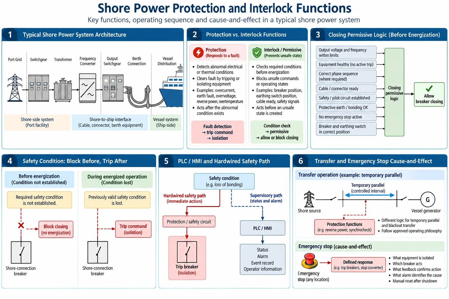
保护装置和锁止装置在岸电系统中执行不同的功能。 保护功能会在存在电气或热量异常的情况下进行响应。 锁止和允许条件可以防止出现不安全的命令或操作状态。.
因此,一套完整的岸上电力保护理念需要不止于一套继电器功能列表。 它应该定义哪些内容会被检测到、哪些内容会被阻止或触发、哪些设备需要采取行动、该行动如何得到确认,以及在系统恢复到初始状态之前需要满足哪些条件。.
为什么岸电需要保护和锁止装置?
岸电连接跨越了多个电气和控制边界。 根据系统的不同,电力回路可能包括配电网、开关柜、变压器、调频器、输出馈线、锚固连接以及船舶配电系统。.
电气异常已经存在
- 短路或过电流
- 地球故障
- 电压或频率异常
- 变压器过热
- 意外的逆向电力
回复: 在必要时发现并隔离。.
将形成不安全状态
- 接地开关状态与关闭状态冲突
- 安全状况尚未确定
- 紧急制动功能仍然有效
- 电缆或连接接口尚未准备就绪
回复: 允许模式或锁模模式会阻止操作。.
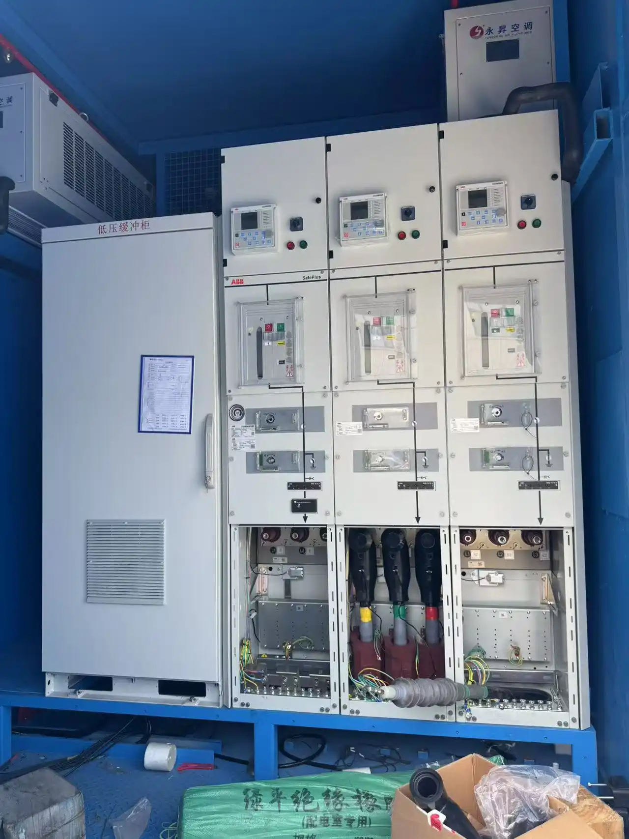
在一种岸上供电配置中,输出开关设备包含过电流、过电压、地电故障、逆电流和失平衡保护功能。同样的一套开关设备还配备了锁止装置,旨在防止断路器和接地开关操作出现错误。.
保护始于实际的电力路径
电力保护应从实际的单线图开始,而不是从继电器提供的功能列表开始。.
基于转换器的系统尤其重要。输入端的电气条件并不一定与输出端或船舶端的电气条件相同。.
在一种 630 kVA 的工程配置中,短路研究被明确分为以下几个部分: 位于变流器前方和变流器输出端(或船体)处的系统。.
但这并不意味着所有频率转换器都具有相同的故障电流特性。 转换器的拓扑结构和控制策略很重要。但这并不意味着保护研究必须遵循实际的源、变压器、转换器、电缆和船舶的布置。.
对于每个相关保护区域,设计需要确定可能存在的异常情况,以及其测量范围、应响应的保护功能、所需的断路器或转换器动作以及在主动作不完成的情况下应提供的备用措施。.
IEC/IEEE 80005-1 将 HV 岸接头视为包含岸上配电系统的系统, 连接和接口设备、变压器或逆变器、调频转换器、船舶配电系统 以及相关的控制、监测和联动系统。.
关于更广泛的设备配置,请参阅 岸电系统架构与组件.
在能量化之前:什么应该阻止关闭?
供电电压并不一定意味着连接是安全的。.
电气化和连接准备情况
- 可接受的输出电压和频率
- 设备健康状况
- 必要时保持正确的相位顺序
- 有线或连接器准备就绪
- 选定的泊位和所需船舶信号
安全性和开关准备状态
- 已建立的适用安全或飞行员回路
- 已证明的接地或连接条件
- 没有出现任何紧急停机情况
- 断路器和接地开关的位置正确
- 所需关键或机械锁紧装置已满足
在其中一个项目中,泊位接口监控除了包含开关柜和变压器信息外,还包括了可进行电缆连接的准备状态、紧急断电状态和接地状态信息。.
同一工程证据基础上的调试序列也要求使用连接电缆。 还要检查插座盒、遵循安全键序列、接地开关和断路器。 要将岸上供水置于所需状态,才能达到所需的输出条件, 同步和最终连接之前,相位顺序需要确认。.
能量激活后:当失去的安全条件变成危险时
安全条件的丧失情况不同,因此需要采取不同的应对措施。.
一个工程配置提供了有用的例子。船舶与岸之间的失联 等电连接电路启动了对断路器的硬连接响应,而同一情况又发生了。 该信号也被传输到了PLC。该安排也防止了断路器关闭或进入断路状态。 在粘接条件不可用时的操作位置。.
对于 IEC/IEEE 80005-1 范围内的 HVSC 系统,打开定义的安全回路与 船舶和岸边 HVSC 断路器的自动开启。相同的详细要求 对于 LV 系统,不应将其视为默认值。 IEC/IEEE 80005-3:2025 规定了当前的 LVSC 框架。 以其明确的范围为限。.

关于连接装置和接地保护装置的详细设计,请参阅 岸上电源配电点等电点连接和接地.
安全行动和监督控制具有不同的作用
PLC 和 HMI 系统可以处理操作序列、模式选择、设备状态、报警、远程命令以及事件信息。.
所需的安全措施不一定需要依赖于相同的监管路径。.
上述等电连接示例采用了这种配置:保护响应具有固定的断路路径,同时该情况也被报告给 PLC。.
关于 IACS 建议 182 所涵盖的船舶侧 HVSC 系统,保护和安全系统 建议遵循安全可靠的原理和固件设计原则。 IEC/IEEE 80005-2 提供了另一种方法。 通过解决非紧急功能上的船舶与岸基数据通信问题,实现了有用的边界。.
答案取决于电压等级、适用的标准、等级要求以及已批准的项目架构。.
开关锁可以防止不安全的状态发生
在电气保护功能需要发挥作用之前,应该避免出现一些不安全情况。 可拆卸的开关设备就是一个明显的例子。.
在其中一个项目的规范中,锁止装置防止了诸如在负载下移动断路器卡车、在接地开关处于开启状态下将断路器移动到位、进入有电的区域以及将接地开关连接到有电电路等操作。此外,相关上游和下游开关设备之间也采用了锁止装置。.
这些断路器并不能替代短路或过电流保护。 继电器会在出现电气异常时响应。开关锁止装置可以防止操作员或控制命令导致设备状态发生异常。.
因此,一个相互验证的测试应该能证明逻辑的两个方面: 允许的序列必须有效,禁止状态必须保持锁定状态。.
转移和紧急关闭需要明确原因与后果
保护行为随操作状态而变化。 岸上转运就是最清晰的例子之一。.
临时并行更改保护逻辑
断电或在启动前切换操作不会产生与同步临时并行操作相同的保护条件。.
在临时并行传输期间,岸上源设备和船上发电机都可以连接一段时间。在此期间,保护装置必须区分预期传输状态与需要隔离的异常状态。.
一项工程参考资料指出,当船舶和岸基操作参数在实时连接或断开连接期间存在差异时,逆功率可能是一种传输相关问题。.
因此,传输设计需要定义传输方法、允许的并行持续时间、电源预期方向以及在传输未按预期完成时应采取的行动。.
IACS 的建议 182 在船侧方面反映了这一区分,即将临时平行转移与停电转移分别处理。.
保护措施必须遵循已批准的运营理念。 详细的逆功率检测和控制功能已包含在 岸上供电反向供电保护.
紧急停止是一种因果关系功能
紧急停止按钮本身并不是紧急关闭的理念。.
设计还必须确定启动条件后的过程:什么会被隔离、哪个断路器会启动、需要什么样的设备响应、什么反馈会确认动作的有效性、什么报警会识别原因,以及在重置之前需要恢复哪些条件。.
在一次调试过程中,船舶与岸基连接或断开连接期间出现异常情况,导致需要启动紧急停止操作并终止测试。.
在IACS建议182所涵盖的VHSC框架的船侧上, 启动紧急关闭的条件包括设备间接连接持续性丧失等情况。 安全电路故障、紧急停止启动以及某些 HV 电缆或连接器保护事件。 确切的行动矩阵仍取决于项目具体情况。.
设置和测试必须证明完整的保护链
保护功能、保护设置和保护测试点是不同的概念。.
保护功能
定义了检测到的条件。.
Setting and test point
The setting defines when the function operates. The test point is the condition applied during verification.
Why Settings Cannot Be Copied
Protection settings depend on the actual electrical system. Relevant inputs include source fault level, transformer impedance, converter fault-current or current-limit behavior, cable impedance, vessel distribution, upstream and downstream protection, transfer philosophy and required selectivity.
One project procedure used a 110% current condition for an overload test, secondary-current injection at 200% rated current for inverse-time protection verification, and a higher-current injection for instantaneous protection testing. Those were test conditions in that procedure, not universal shore power relay settings.
Standards and Class rules define the compliance framework. The final setting schedule still has to follow the actual project study. See 岸上供电标准与合规性.
From Relay Test to Complete Cause-and-Effect Test
1. Engineering study
Fault levels, protection zones, selectivity and intended trip targets.
2. Device test
Relay, sensor or protection function itself.
3. Interlock test
Both permitted and prohibited states.
4. End-to-end integration
Condition → detection → logic → block/trip → equipment action → feedback → alarm/event → reset.
Factory testing can verify internal wiring, protection logic, simulated interfaces and equipment response. Final cable connections, berth equipment, pilot circuits, bonding arrangements and vessel-side signals may only be available during SAT or first-connection testing.
What Information Is Needed for a Protection Review?
A protection review should start with project data rather than a generic relay list.
| 项目投入 | 为什么这件事很重要 |
|---|---|
| Shore-side single-line diagram | Defines sources, protection zones and possible trip targets |
| Vessel-side single-line diagram | Defines the vessel interface and transfer boundary |
| 可用短路容量 | Supports breaker duty and protection coordination |
| Transformer ratings, vector groups and impedances | Affects fault and grounding behavior |
| Converter fault-current / current-limit data | Defines converter-side protection behavior |
| 电缆尺寸和长度 | Adds impedance and affects protection boundaries |
| Earthing and neutral arrangement | Determines earth-fault behavior |
| Pilot, bonding and connection signals | Defines permissives and safety logic |
| Transfer method | Determines synchronization and reverse-power requirements |
| E-stop / cause-and-effect | Defines shutdown scope and reset logic |
| Applicable standard and Class | Defines the compliance boundary |
| FAT, SAT and first-connection scope | Defines how the complete response will be verified |
If some of these inputs are unavailable, the design will contain assumptions. Those assumptions should be identified and confirmed before final settings and acceptance procedures are frozen.
常见问题解答
岸上电源保护与断路器之间的区别是什么?
Protection responds to an abnormal electrical or thermal condition. An interlock prevents an unsafe command or operating state. A complete shore power system needs both because an electrical fault and an unsafe operating sequence are different failure mechanisms.
是否可以将所有岸上电源保护功能集成到 PLC 中?
There is no universal answer that applies to every LV and HV installation. The required architecture depends on the applicable standard, Class requirements and project safety philosophy. Supervisory PLC/HMI functions and immediate safety actions can have different responsibilities.
如果飞行员失踪或安全信号阻止了系统关闭或启动,该怎么办?
It depends on when the condition is lost and on the approved cause-and-effect. Before energization, an unproven required condition can remove the closing permissive. If a monitored safety condition is lost during energized operation, the defined protection or shutdown action may be required.
为什么岸电保护设置是针对项目的?
Because fault current, transformer impedance, converter behavior, cable impedance, vessel distribution and transfer method all affect protection coordination. Two systems with the same power rating can still require different settings.
FAT 和 SAT 期间应该测试哪些内容?
More than the relay. Testing should cover the required protection-device response, permitted and prohibited interlock states, actual equipment actions, feedback, alarms and reset path. Final berth, cable and vessel-interface functions may require SAT or first-connection integration testing.
技术参考
- IEC/IEEE 80005-1:2019 with applicable amendments — High voltage shore connection (HVSC) systems.
- IEC/IEEE 80005-2:2016 — Data communication for monitoring and control.
- IEC/IEEE 80005-3:2025 — Low-voltage shore connection (LVSC) systems.
- IACS Recommendation No.182 — Onshore Power Supply — protection, safety, interlocking, transfer and emergency-shutdown considerations.
Review the Protection Philosophy Before Finalizing the Settings
Before finalizing protection settings, provide the actual shore and vessel single-line diagrams, source fault level, transformer and converter data, cable information, earthing and bonding arrangement, pilot and berth-interface signals, transfer method, existing protection and interlock cause-and-effect, applicable standard or Class requirement, and FAT/SAT scope.
These inputs allow the protection zones, closing permissives, trip logic and verification requirements to be reviewed against the real shore power architecture.
提交您的项目需求