
Shore Power Protection and Interlock Functions
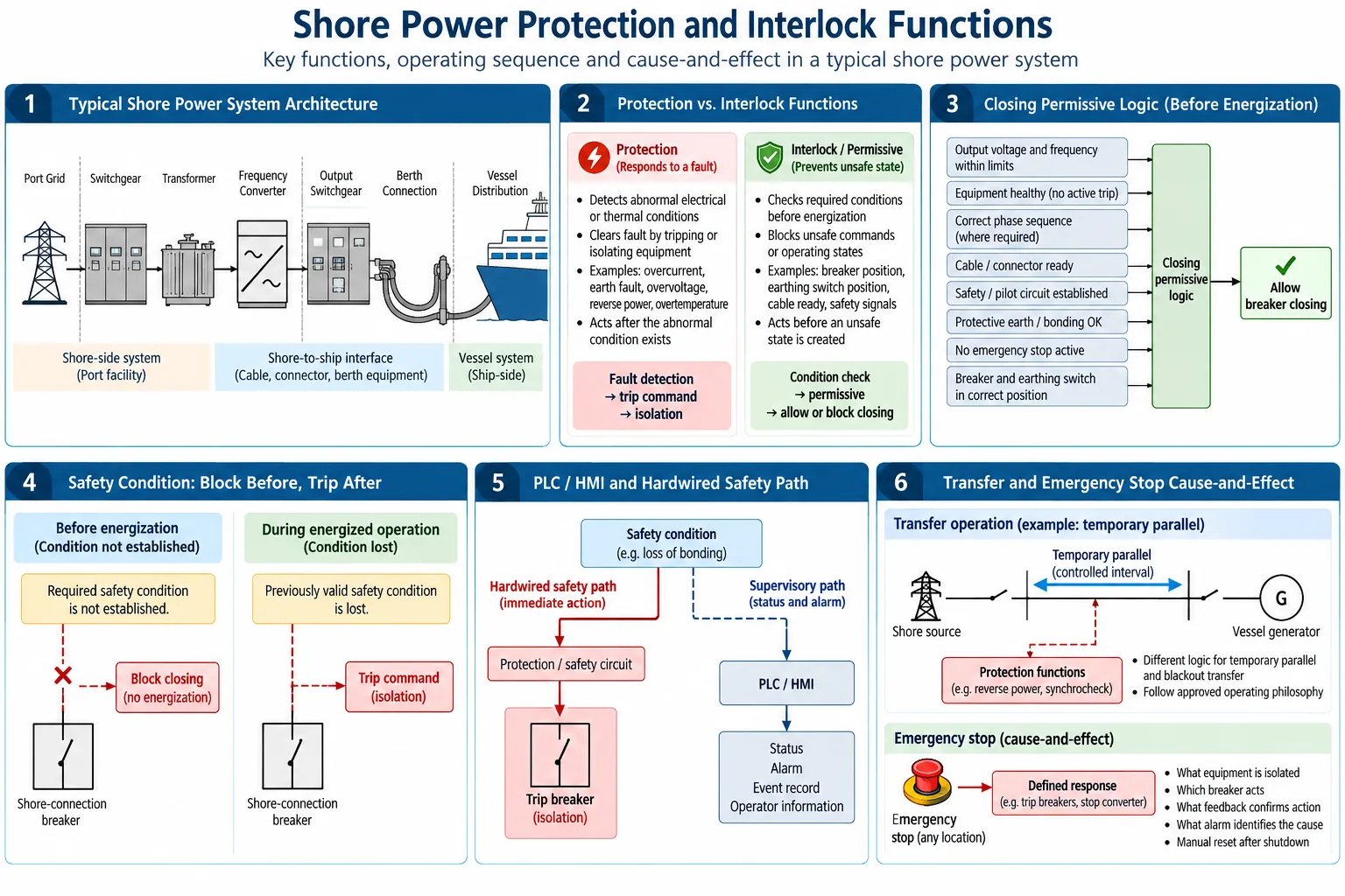
Protection and interlocks do different jobs in a shore power system. Protection responds when an electrical or thermal abnormality already exists. Interlocks and permissives prevent an unsafe command or operating state from being created.
A complete shore power protection philosophy therefore needs more than a relay-function list. It should define what is detected, what is blocked or tripped, which equipment must act, how that action is confirmed, and what conditions are required before the system can be reset.
Why Shore Power Needs Both Protection and Interlocks
A shore power connection crosses several electrical and control boundaries. Depending on the system, the power path can include the port grid, switchgear, transformers, a frequency converter, output feeders, the berth connection and the vessel distribution system.
Electrical abnormality already exists
- Short circuit or overcurrent
- Earth fault
- Abnormal voltage or frequency
- Transformer overtemperature
- Unintended reverse power
Response: detect and isolate where required.
Unsafe state would be created
- Earthing-switch state conflicts with closing
- Safety condition is not established
- Emergency stop remains active
- Cable or connection interface is not ready
Response: permissive or interlock prevents the operation.
In one shore power configuration, the output switchgear included overcurrent, overvoltage, earth-fault, reverse-power and unbalance protection. The same switchgear also incorporated interlocks intended to prevent incorrect breaker-truck and earthing-switch operations.
Protection Starts with the Actual Power Path
Shore power protection should start with the actual single-line diagram, not with a list of functions available in a relay.
A converter-based system makes this especially important. The electrical conditions on the incoming side are not automatically the same as those on the converter-output or vessel side.
In one 630 kVA engineering configuration, the short-circuit study was explicitly divided into the system ahead of the converter and the converter-output, or vessel, side.
That does not mean every frequency converter has the same fault-current characteristic. Converter topology and control strategy matter. It does mean that the protection study has to follow the actual source, transformer, converter, cable and vessel arrangement.
For each relevant protection zone, the design needs to establish the possible abnormal condition, where it is measured, which protective function responds, which breaker or converter action is required, and what provides backup if the primary action does not complete.
IEC/IEEE 80005-1 treats HV shore connection as a system that includes shore distribution, connection and interface equipment, transformers or reactors, frequency converters, ship distribution, and the associated control, monitoring and interlocking systems.
For the wider equipment arrangement, see shore power system architecture and components.
Before Energization: What Should Block Closing?
Available voltage does not necessarily mean the connection is safe to energize.
Electrical and connection readiness
- Acceptable output voltage and frequency
- Healthy equipment status
- Correct phase sequence where required
- Cable or connector ready
- Selected berth and required vessel signals
Safety and switching readiness
- Applicable safety or pilot circuit established
- Protective-earth or bonding condition proven
- No active emergency shutdown
- Breaker and earthing-switch positions correct
- Required key or mechanical interlocks satisfied
In one project, berth-interface monitoring included cable-connection-ready, emergency-disconnect and grounding status in addition to switchgear and transformer information.
A commissioning sequence from the same engineering evidence base also required the connection cable and socket box to be checked, a safety-key sequence to be followed, the earthing switch and breaker to be placed in the required states, the shore supply to reach its required output condition and phase sequence to be confirmed before synchronization and final connection.
After Energization: When a Lost Safety Condition Becomes a Trip
A safety condition can require a different response depending on when it is lost.
One engineering configuration provides a useful example. Loss of the ship-to-shore equipotential-bonding circuit initiated a hardwired response to the breaker while the same condition was also transmitted to the PLC. The arrangement also prevented the breaker from closing or entering the operating position while the bonding condition was unavailable.
For HVSC systems within IEC/IEEE 80005-1 scope, opening of the defined safety loop is tied to automatic opening of the ship- and shore-side HVSC circuit breakers. The same detailed requirement should not be assumed for LV systems. IEC/IEEE 80005-3:2025 provides the current LVSC framework for its defined scope.

For the bonding and protective-earth design itself, see shore power equipotential bonding and grounding.
Safety Action and Supervisory Control Have Different Roles
PLC and HMI systems can handle operating sequences, mode selection, equipment status, alarms, remote commands and event information.
The required safety action does not necessarily have to depend on that same supervisory path.
The equipotential-bonding example above used this arrangement: the protective response had a hardwired breaker path while the condition was also reported to the PLC.
For the ship-side HVSC scope covered by IACS Recommendation 182, protection and safety systems are recommended to follow fail-safe and hard-wired principles. IEC/IEEE 80005-2 provides another useful boundary by addressing ship-to-shore data communication for non-emergency functions.
The answer depends on the voltage level, applicable standard, Class requirements and the approved project architecture.
Switching Interlocks Prevent Unsafe Physical States
Some unsafe conditions should be prevented before an electrical protection function ever has to operate. Withdrawable switchgear is a clear example.
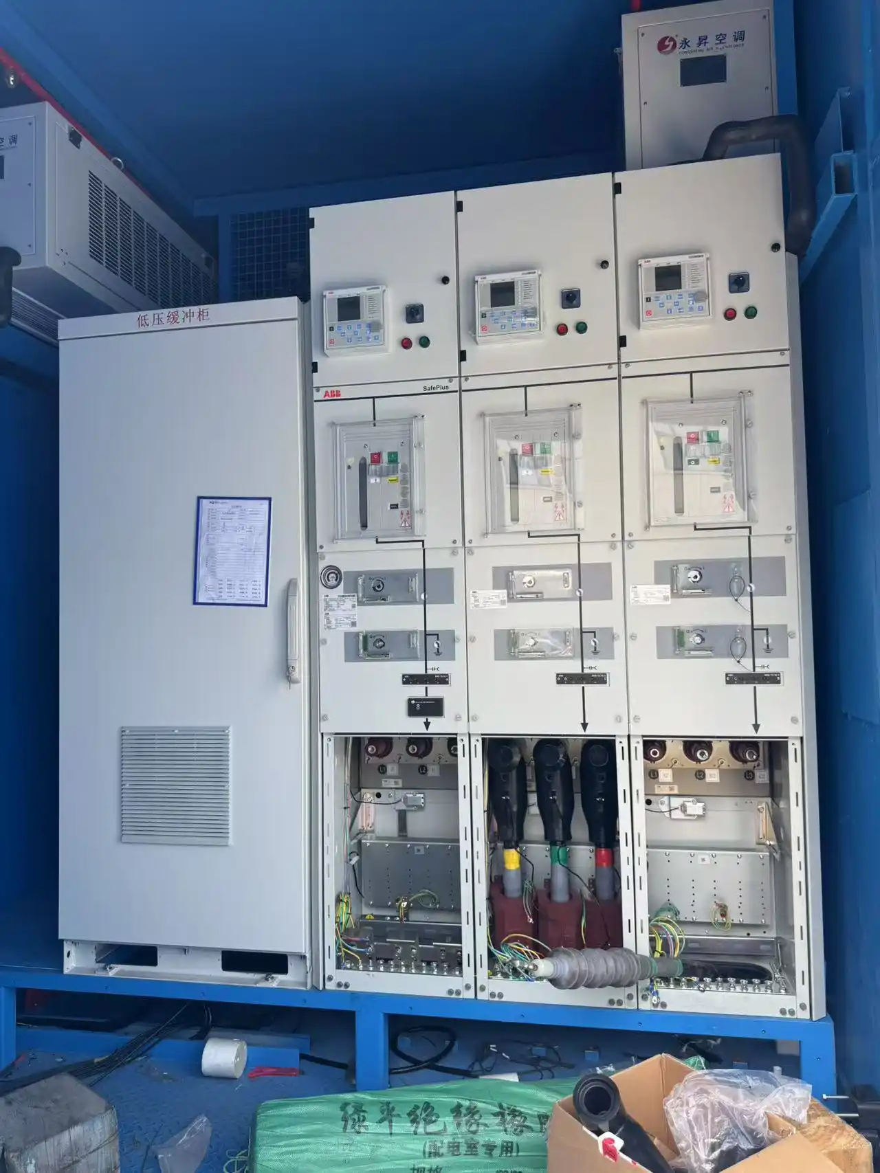
In one project specification, the interlock arrangement prevented operations such as moving a breaker truck under load, moving the breaker into position while the earthing switch was engaged, entering an energized compartment and closing an earthing switch onto a live circuit. Interlocks were also provided between related upstream and downstream switching devices.
These interlocks do not replace short-circuit or overcurrent protection. A relay responds after an electrical abnormality exists. A switching interlock can prevent an operator or control command from creating an invalid equipment state.
An interlock test should therefore prove both sides of the logic: the permitted sequence must work, and prohibited states must remain blocked.
Transfer and Emergency Shutdown Need Defined Cause-and-Effect
Protection behavior changes with the operating state. Ship-to-shore transfer is one of the clearest examples.
Temporary Parallel Changes Protection Logic
A blackout or break-before-make transfer does not create the same protection conditions as synchronized temporary parallel operation.
During temporary parallel transfer, the shore source and vessel generator may both be connected for a controlled interval. Protection then has to distinguish an intended transfer condition from an abnormal state that requires isolation.
One engineering reference identified reverse power as a possible transfer-related condition when ship and shore operating parameters differed during live connection or disconnection.
The transfer design therefore needs to define the transfer method, permitted parallel duration, expected direction of power and the action required if the transfer does not complete as intended.
IACS Recommendation 182 reflects this distinction on the ship side by treating temporary parallel transfer separately from blackout transfer.
Protection must follow the approved operating philosophy. Detailed reverse-power detection and control are covered in shore power reverse power protection.
Emergency Stop Is a Cause-and-Effect Function
An emergency-stop button is not, by itself, an emergency-shutdown philosophy.
The design still has to define what follows the initiating condition: what is isolated, which breaker acts, what equipment response is required, what feedback confirms the action, what alarm identifies the cause and what conditions must be restored before reset.
In one commissioning procedure, abnormal conditions during ship-shore connection or disconnection required the emergency stop to be operated and the test to be terminated.
On the ship side of the HVSC framework covered by IACS Recommendation 182, emergency-shutdown initiating conditions include events such as loss of equipotential-bonding continuity, loss of a safety circuit, emergency-stop activation and certain HV cable or connector protection events. The exact action matrix remains project-specific.
Settings and Tests Must Prove the Complete Protection Chain
A protection function, a protection setting and a protection test point are different things.
Protection function
Defines what condition is being detected.
Setting and test point
The setting defines when the function operates. The test point is the condition applied during verification.
Why Settings Cannot Be Copied
Protection settings depend on the actual electrical system. Relevant inputs include source fault level, transformer impedance, converter fault-current or current-limit behavior, cable impedance, vessel distribution, upstream and downstream protection, transfer philosophy and required selectivity.
One project procedure used a 110% current condition for an overload test, secondary-current injection at 200% rated current for inverse-time protection verification, and a higher-current injection for instantaneous protection testing. Those were test conditions in that procedure, not universal shore power relay settings.
Standards and Class rules define the compliance framework. The final setting schedule still has to follow the actual project study. See shore power standards and compliance.
From Relay Test to Complete Cause-and-Effect Test
1. Engineering study
Fault levels, protection zones, selectivity and intended trip targets.
2. Device test
Relay, sensor or protection function itself.
3. Interlock test
Both permitted and prohibited states.
4. End-to-end integration
Condition → detection → logic → block/trip → equipment action → feedback → alarm/event → reset.
Factory testing can verify internal wiring, protection logic, simulated interfaces and equipment response. Final cable connections, berth equipment, pilot circuits, bonding arrangements and vessel-side signals may only be available during SAT or first-connection testing.
What Information Is Needed for a Protection Review?
A protection review should start with project data rather than a generic relay list.
| Project input | Why it matters |
|---|---|
| Shore-side single-line diagram | Defines sources, protection zones and possible trip targets |
| Vessel-side single-line diagram | Defines the vessel interface and transfer boundary |
| Available short-circuit capacity | Supports breaker duty and protection coordination |
| Transformer ratings, vector groups and impedances | Affects fault and grounding behavior |
| Converter fault-current / current-limit data | Defines converter-side protection behavior |
| Cable sizes and lengths | Adds impedance and affects protection boundaries |
| Earthing and neutral arrangement | Determines earth-fault behavior |
| Pilot, bonding and connection signals | Defines permissives and safety logic |
| Transfer method | Determines synchronization and reverse-power requirements |
| E-stop / cause-and-effect | Defines shutdown scope and reset logic |
| Applicable standard and Class | Defines the compliance boundary |
| FAT, SAT and first-connection scope | Defines how the complete response will be verified |
If some of these inputs are unavailable, the design will contain assumptions. Those assumptions should be identified and confirmed before final settings and acceptance procedures are frozen.
Frequently Asked Questions
What is the difference between shore power protection and an interlock?
Protection responds to an abnormal electrical or thermal condition. An interlock prevents an unsafe command or operating state. A complete shore power system needs both because an electrical fault and an unsafe operating sequence are different failure mechanisms.
Can all shore power protection be implemented in the PLC?
There is no universal answer that applies to every LV and HV installation. The required architecture depends on the applicable standard, Class requirements and project safety philosophy. Supervisory PLC/HMI functions and immediate safety actions can have different responsibilities.
Should a missing pilot or safety signal block closing or trip the system?
It depends on when the condition is lost and on the approved cause-and-effect. Before energization, an unproven required condition can remove the closing permissive. If a monitored safety condition is lost during energized operation, the defined protection or shutdown action may be required.
Why are shore power protection settings project-specific?
Because fault current, transformer impedance, converter behavior, cable impedance, vessel distribution and transfer method all affect protection coordination. Two systems with the same power rating can still require different settings.
What should be tested during FAT and SAT?
More than the relay. Testing should cover the required protection-device response, permitted and prohibited interlock states, actual equipment actions, feedback, alarms and reset path. Final berth, cable and vessel-interface functions may require SAT or first-connection integration testing.
Technical References
- IEC/IEEE 80005-1:2019 with applicable amendments — High voltage shore connection (HVSC) systems.
- IEC/IEEE 80005-2:2016 — Data communication for monitoring and control.
- IEC/IEEE 80005-3:2025 — Low-voltage shore connection (LVSC) systems.
- IACS Recommendation No.182 — Onshore Power Supply — protection, safety, interlocking, transfer and emergency-shutdown considerations.
Review the Protection Philosophy Before Finalizing the Settings
Before finalizing protection settings, provide the actual shore and vessel single-line diagrams, source fault level, transformer and converter data, cable information, earthing and bonding arrangement, pilot and berth-interface signals, transfer method, existing protection and interlock cause-and-effect, applicable standard or Class requirement, and FAT/SAT scope.
These inputs allow the protection zones, closing permissives, trip logic and verification requirements to be reviewed against the real shore power architecture.
Send Your Project Requirements