Transformer Test Power Source

Transformer Induced Voltage Test

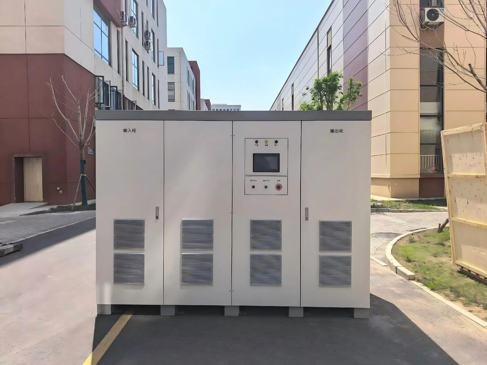
Transformer induced voltage and induced withstand tests require a controllable AC excitation source matched to the required test voltage, frequency, capacity and transformer test arrangement. SDACME provides variable-frequency test power supplies for power transformer testing, with configurable output for induced voltage test applications.
5–2000 kVA Configurable capacity range
45–200 Hz Adjustable output frequency
Up to 1000 V L-L Configurable AC output
Transformer-Isolated Three-phase sine-wave output
Transformer Test Application
Transformer test power supply installation for induced voltage testing

Variable-Frequency Excitation

Power Source for Transformer Induced Voltage Testing

Output capacity, voltage, frequency and connection are selected according to the transformer and the applicable test requirements.

45–200 Hz 0.1 Hz Adjustment Sine-Wave Output

Induced Voltage Testing

What Is a Transformer Induced Voltage Test?

A transformer induced voltage test uses controlled AC excitation to establish the required electrical test condition in the transformer under test. From the power-source side, the key project requirements are the required voltage, frequency, power capacity and output configuration.

Direct answer

The variable-frequency power supply provides the excitation power required for the transformer test. It is one part of the overall test arrangement, rather than the complete transformer test system by itself.

What the Power Source Provides

  • Controlled AC output voltage
  • Adjustable output frequency
  • Required test power capacity
  • Transformer-isolated sine-wave output

What the Complete Test Arrangement May Include

Transformer-side connections, voltage measurement, protection, instrumentation and, where required, partial-discharge measurement are configured according to the transformer and the applicable test procedure.

Controllable Excitation

Variable-Frequency Excitation for Induced Testing

The excitation source should provide a controllable frequency range that can be configured for the transformer and the applicable induced-voltage test procedure, rather than being limited to the incoming mains frequency alone.

45–200 Hz Adjustable output-frequency range
0.1 Hz Frequency adjustment step
≤ ±0.01% Frequency stability
Available AC Supply Project input power
→
Variable-Frequency Test Power Source Controlled voltage and frequency output
→
Configurable Test Excitation Matched to transformer test requirements

The required test frequency is determined by the transformer test requirement and the applicable procedure. It should not be assumed that one fixed frequency applies to every transformer or every induced-voltage test.

Test Power Source

Power Source Requirements for Induced Voltage Testing

The power source must be selected according to the transformer, required excitation conditions and project test arrangement. SDACME configurations provide adjustable voltage and frequency for transformer test applications.

Capacity

5–2000 kVA

Configurable series capacity range.

Output Voltage

0–1000 V L-L

Applicable output configuration.

Frequency

45–200 Hz

Adjustable variable-frequency output.

Adjustment

0.1 Hz

Frequency adjustment step.

Frequency Stability

≤ ±0.01%

Series technical specification.

Output

Sine Wave

Three-phase, transformer-isolated output.

Final ratings and output configuration are selected according to the transformer and project test requirements. The maximum values above should not be interpreted as a guarantee that every capacity, voltage and frequency combination is available in every configuration.

Conceptual Test Layout

Typical Transformer Induced Voltage Test Power Arrangement

The power source forms the excitation stage of the transformer test arrangement. The exact transformer connections, voltage measurement and instrumentation depend on the transformer design and the applicable test procedure.

Available AC Supply Site input power
→
SDACME Variable-Frequency Test Power Source Controls output voltage, frequency and available test power
→
Transformer Excitation Connection Project-specific connection arrangement
→
Transformer Under Test With required test and measurement arrangement

Conceptual arrangement for explaining the role of the test power source. It is not a wiring diagram or a complete transformer test-system schematic.

Power-Source Scope

Adjustable AC output, variable frequency, required capacity and transformer-isolated output are configured for the application.

Project-Specific Scope

Transformer connections, instrumentation and additional test equipment are defined according to the transformer and test procedure.

Engineering Selection

How to Select the Induced Voltage Test Power Source

Power-source selection starts with the transformer and the required test conditions. Supplying the following project information allows the required capacity, voltage, frequency and output configuration to be reviewed. For a broader overview of power-source selection across different transformer test duties, see our transformer test power supply guide.

01

Transformer Type & Rating

Provide transformer type, rated power and relevant winding information.

02

Required Test Voltage

State the required test condition or target excitation requirement.

03

Test Frequency / Procedure

Provide the required frequency or applicable transformer test procedure.

04

Required Test Capacity

Provide known excitation current, capacity or related test-load information.

05

Available Input Supply

Confirm the power available at the transformer test site.

06

PD Measurement Requirement

State whether partial-discharge measurement is included in the test arrangement.

Have a transformer test requirement?

Send the transformer data and test conditions. SDACME can review the suitable variable-frequency power-source configuration for the application.

Send Transformer Test Requirements

Related Test Terminology

DVDF, Induced Withstand and ACLD Test Configurations

Transformer test requirements may use several related terms. They should not automatically be treated as identical test procedures because the required voltage, frequency, duration and measurement arrangement can differ.

INDUCED TESTING

Induced Voltage / Induced Withstand

General terminology for transformer induced-voltage dielectric test requirements using controlled excitation.

DVDF

Double Voltage Double Frequency

A commonly used transformer-test expression associated with induced overvoltage testing. Exact requirements remain procedure-dependent.

ACLD

Long-Duration Induced AC Testing

Some test programs specify long-duration induced AC voltage conditions and may include additional measurement requirements.

Common power-source requirement

These applications require an excitation source whose voltage, frequency and capacity can be configured for the transformer and the applicable test procedure. The exact test parameters should be confirmed project by project.

IVPD Relationship

When Partial Discharge Measurement Is Included

The induced-voltage excitation function and the partial-discharge measurement function are related, but they are separate parts of the test arrangement.

Excitation Power Source

Establishes the required transformer excitation condition through controlled voltage, frequency and available test power.

+

PD Measuring Circuit

Where PD measurement is required, the measuring circuit performs the partial-discharge measurement using the appropriate coupling and measurement equipment.

Need more detail about the relationship between the power source, coupling network and PD detector?

Transformer Partial Discharge Test

Operating Visibility

Control, Monitoring and Protection for Test Operation

The power source provides operating information and protection functions required for controlled transformer test-power operation.

Monitoring

Output Voltage
Output Current
Output Frequency
Output Power

Protection

Overcurrent
Short Circuit
Overload
Overtemperature
Fault Indication
Emergency Stop
Control and protection settings are configured according to the selected power-source configuration and project operating requirements.

Manufacturing & Application Evidence

Built for Transformer Test Applications

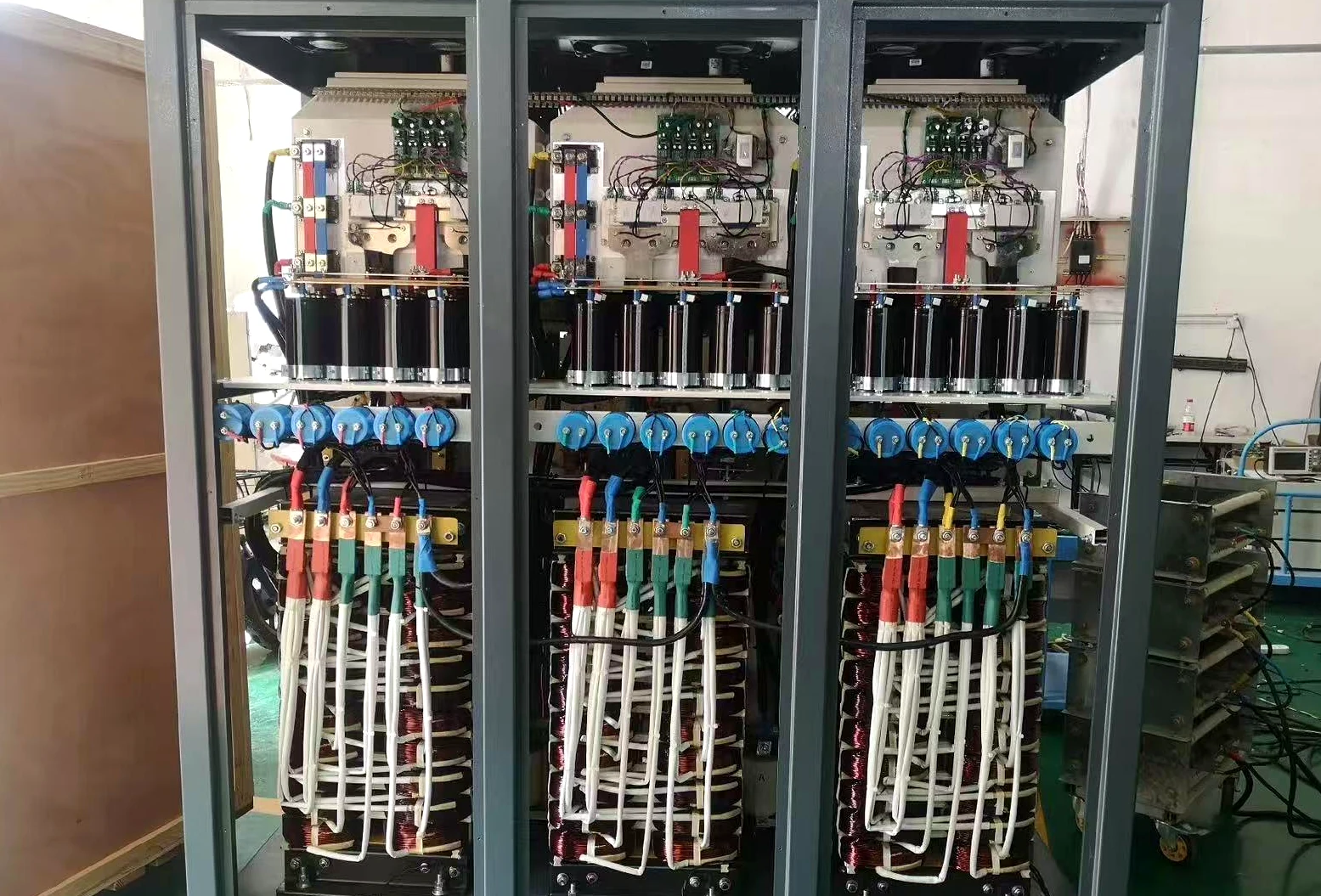
SDACME has documented transformer test-station projects using high-capacity partial-discharge-free variable-frequency power sources, with project configurations ranging from hundreds of kVA to above 1 MVA.
450 kVA Documented Project 1000 kVA Documented Project 1500 kVA Documented Projects 1600 kVA Documented Project
Partial discharge-free variable-frequency power supply in workshop assembly

Workshop Assembly

Real equipment manufacturing and assembly evidence for high-capacity variable-frequency test-power configurations.
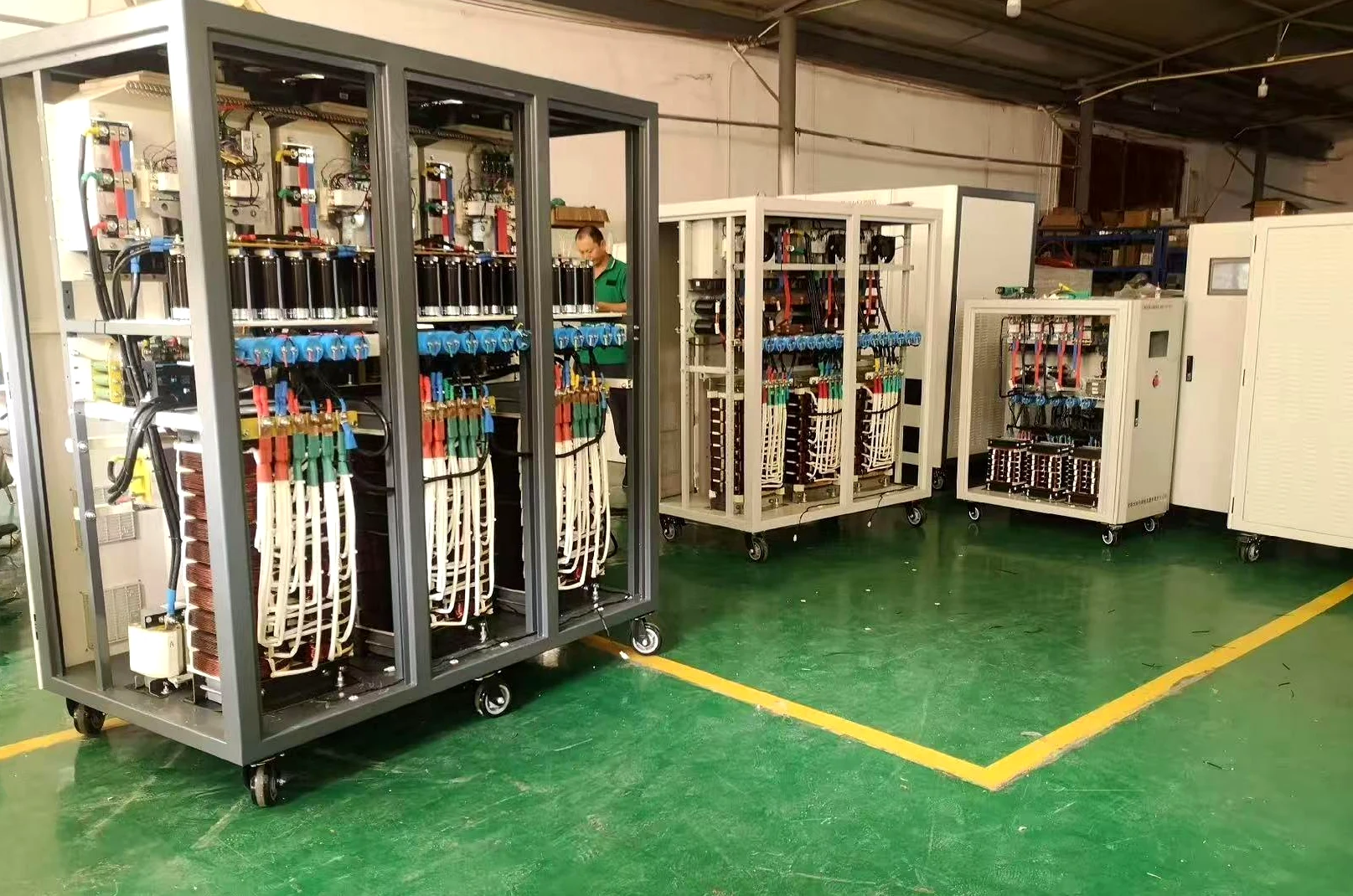
Multiple variable-frequency transformer test power supply units in factory

Multi-Unit Manufacturing

Multiple power-source units provide visual evidence of manufacturing capability for different transformer test-project configurations.

Documented project capacities are project-specific evidence. They do not mean every transformer test application uses the same capacity, test voltage or test-station configuration.

Technical FAQ

Transformer Induced Voltage Test FAQ

Direct answers to common questions about induced-voltage test excitation, variable-frequency power sources and related transformer test arrangements.

What is a transformer induced voltage test?

A transformer induced voltage test uses controlled AC excitation to establish the required electrical test condition in the transformer under test. The excitation power source must be selected for the required voltage, frequency and power capacity.

What type of power source is used for an induced voltage test?

A controllable AC test power source with suitable voltage, frequency and capacity can be used. SDACME provides variable-frequency, transformer-isolated sine-wave power sources for transformer test applications.

Why is adjustable frequency important for induced voltage testing?

Adjustable frequency allows the excitation source to be configured for the transformer and the applicable test procedure rather than being limited to the incoming mains frequency. The exact required frequency remains test-procedure dependent.

How is the required test power capacity selected?

Capacity selection depends on the transformer, required excitation voltage, frequency, expected excitation current and the complete test arrangement. These conditions should be reviewed before selecting the power-source rating.

What is a DVDF transformer test?

DVDF commonly refers to double-voltage double-frequency transformer testing and is associated with induced overvoltage test requirements. It is related to induced voltage testing, but the exact test parameters should follow the applicable transformer test procedure.

Can partial discharge be measured during an induced voltage test?

Yes, where the applicable test arrangement includes partial-discharge measurement. The variable-frequency source provides the excitation condition, while a separate PD measuring circuit performs the partial-discharge measurement.

Project RFQ

Configure Your Transformer Induced Voltage Test Power Source

Send us the transformer rating, required test voltage, test frequency or applicable test procedure, estimated test capacity, available input supply and whether partial-discharge measurement is included. SDACME can review the suitable variable-frequency power-source configuration for your project.

Useful RFQ Information

Transformer type and rated power
Required induced test voltage
Required test frequency or test procedure
Expected test capacity or excitation current
Available site input power
Whether PD measurement is required

Final power-source configuration is confirmed according to transformer data and project test requirements.