
Safe Shore Power Disconnection and Emergency Shutdown
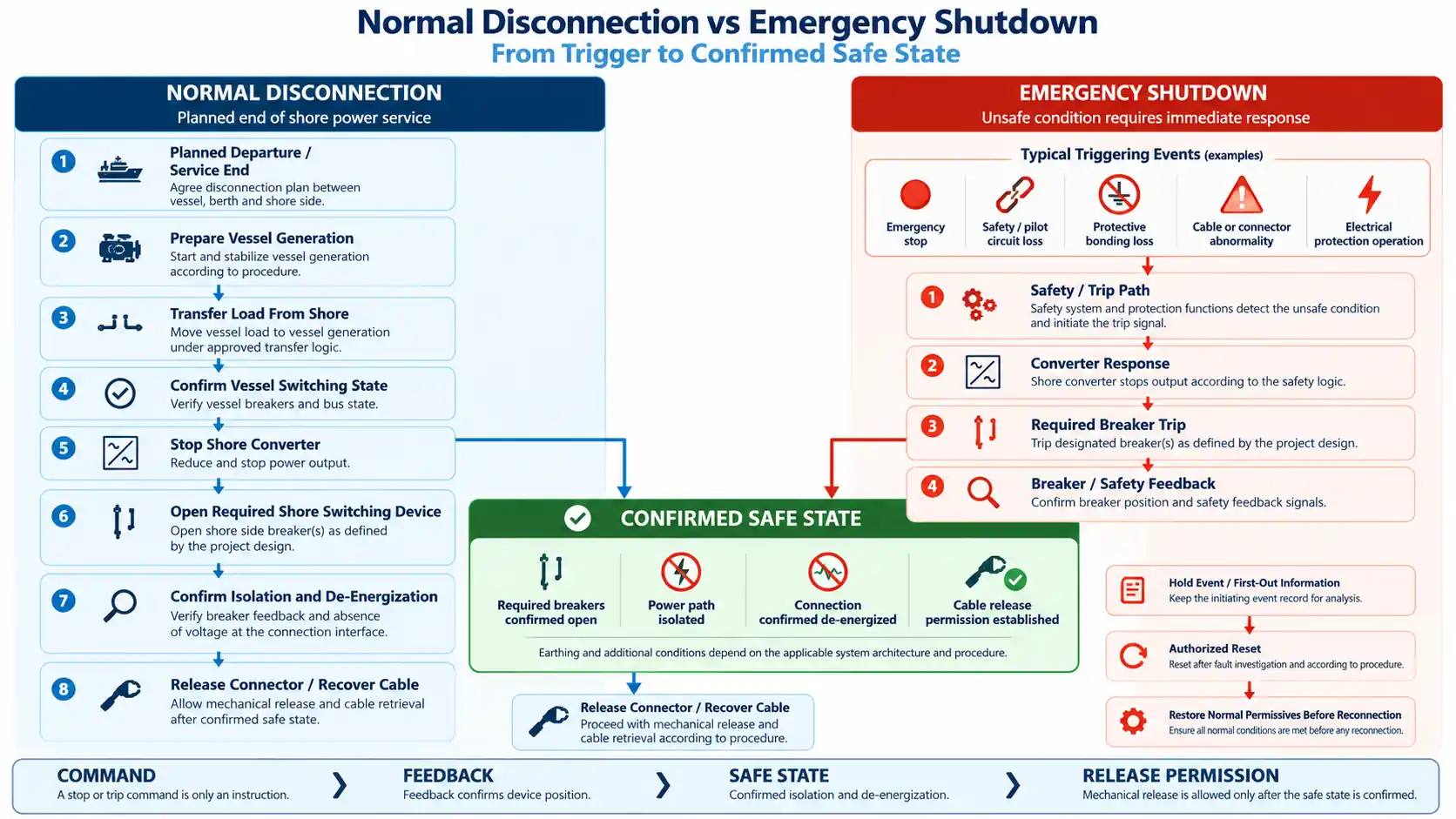
Safe shore power disconnection is not a single “stop” operation. A planned disconnection, an electrical protection trip and an emergency shutdown may all end with the vessel no longer receiving shore power, but they begin for different reasons and should not be treated as the same control sequence.
During a normal departure, the priority is usually to transfer the vessel load in a controlled manner before isolating the shore connection. During an emergency shutdown, the priority changes: the electrical system has to reach a defined safe state because continued operation or continued connection is no longer acceptable.
Safe Shutdown Is a Sequence of Verified States
Automated systems can create a misleading impression that one command represents an entire physical process.
It does not.
The shore power system moves through a sequence of different electrical, mechanical and operating states. Each state proves something specific, but it does not automatically prove the next state.
| State | What Has Happened | What It Does Not Yet Prove |
|---|---|---|
| Operating | Vessel is supplied from shore. | Nothing about readiness to disconnect. |
| Load removed from shore | Vessel load has been transferred or removed. | The shore circuit may still be energized. |
| Converter stopped | Frequency conversion has stopped or received a stop command. | The output switching device may still be closed. |
| Breaker commanded open | An open instruction has been issued. | Physical open state is not yet confirmed. |
| Breaker confirmed open | Position feedback confirms the switching state. | Complete isolation may still require other conditions. |
| Isolation confirmed | Required switching and isolation conditions are satisfied. | Cable handling may still remain mechanically inhibited. |
| Connection de-energized | The connection is confirmed free of the relevant supply voltage. | Release permission may still depend on pilot, locking or operating authority. |
| Cable release permitted | Electrical and mechanical permissives required for handling are satisfied. | Future reconnection is not automatically permitted. |
In one shore power control configuration used as engineering experience, the connection box separately monitored cable-connection readiness, emergency-disconnection state and grounding condition. Cable-reel movement, breaker state and shore power start, stop and reset functions were also handled separately.
That separation matters because a system cannot reliably verify a safe shutdown if several physically different states are collapsed into one generic “Stopped” indication.
Why Shore Power Disconnection Is a Cross-System Problem
A shore power connection crosses several electrical and organizational boundaries.
The vessel contains its own generation, switchboard, protection and operating personnel. The berth contains the physical connection interface, cable handling and local controls. The shore installation can include incoming switchgear, transformers, converters, output switchgear, protection relays, PLCs and SCADA.
Each location sees only part of the total energy path.
This creates a practical engineering problem: no single indication necessarily proves that the complete ship-to-shore circuit has reached the intended condition.
The engineering question is therefore not simply:
The real questions are: Who requests the transition? Who operates each part of the system? What feedback confirms completion? Who has authority to proceed to the next state?
How Ship, Berth and Shore Authority Works in Practice
A practical shore power operation may involve several control locations and several responsible parties.
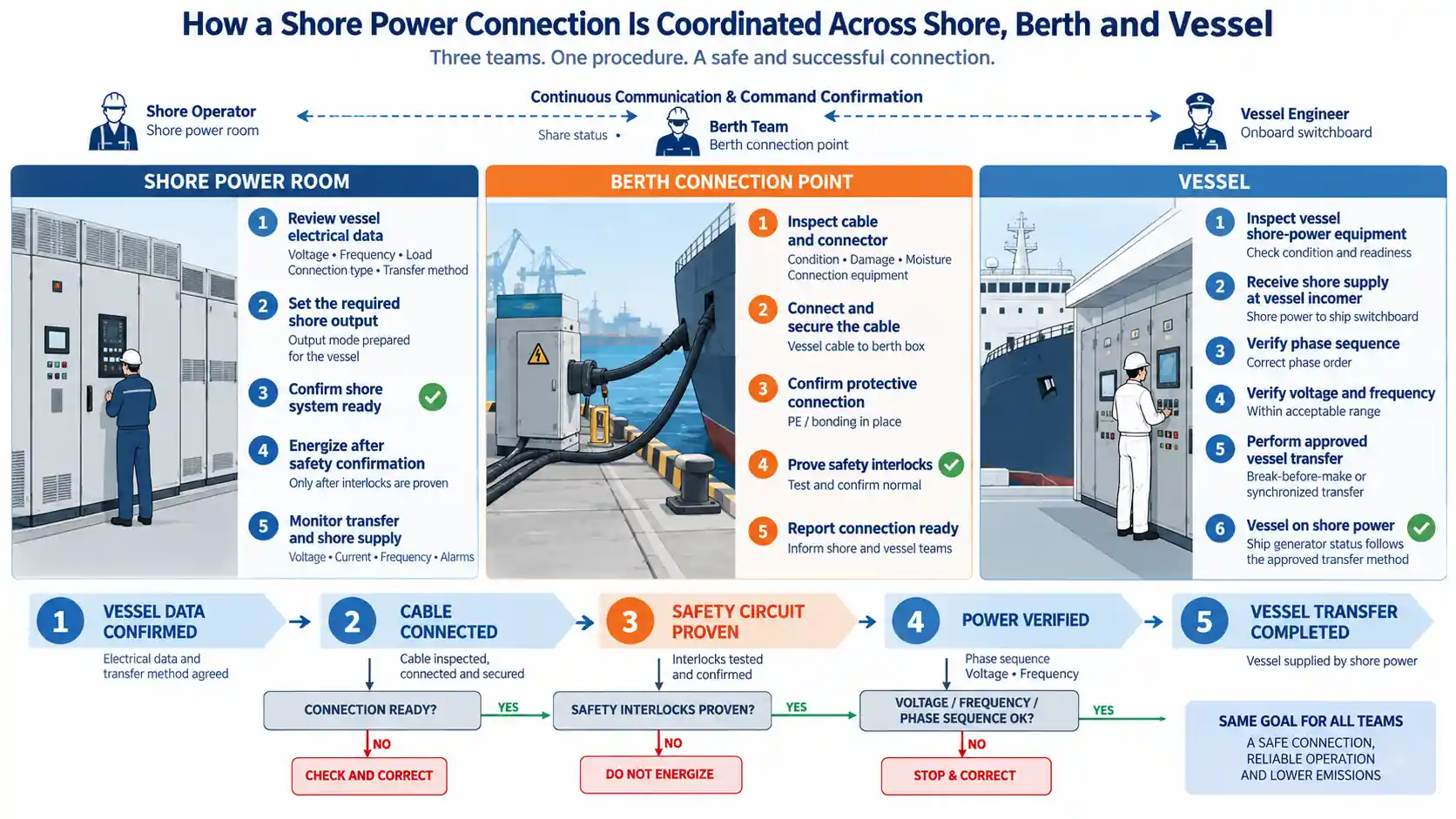
Engineering experience from one commissioning arrangement included separate responsibilities for port personnel, berth personnel, equipment engineers and vessel personnel. Communication between the working locations and formal supply/shutdown confirmations were used before switching activity proceeded.
The value of this arrangement is not paperwork.
It prevents a local assumption from becoming a system-level operating error.
Electrical Confirmation
Vessel load state, converter state, breaker feedback, isolation and de-energization need objective confirmation.
Operational Confirmation
The responsible ship, berth and shore personnel need defined authority to request, confirm and advance the sequence.
Automation can reduce manual actions, but it does not eliminate the need to define who owns the decision that moves the system from one verified state to another.
For the preparation and energization side of the process, see our shore power connection procedure .
Normal Disconnection Starts With the Vessel Load
A normal departure should be treated as a planned source transition rather than an emergency trip.
The vessel first establishes the electrical condition required after shore power is removed. Depending on the vessel, this can mean preparing onboard generators and transferring load according to the approved operating philosophy.
The exact switching sequence depends on the vessel and shore architecture.
That qualification is important because not every vessel supports the same transfer method.
Some systems can use an approved synchronized transfer. Others require an open transition. Where sources overlap, synchronization, protection, reverse-power direction and breaker timing become part of the transfer design.
Controlled Transfer Creates Its Own Protection Problem
Normal disconnection can temporarily create one of the most technically demanding states in the entire shore power operating cycle.
If vessel generation and shore power overlap during a synchronized transfer, the two electrical systems are no longer independent.
Voltage magnitude, frequency, phase angle, generator controls and breaker sequencing all affect the transfer. Incorrect sequencing can result in unintended power flow or reverse power.
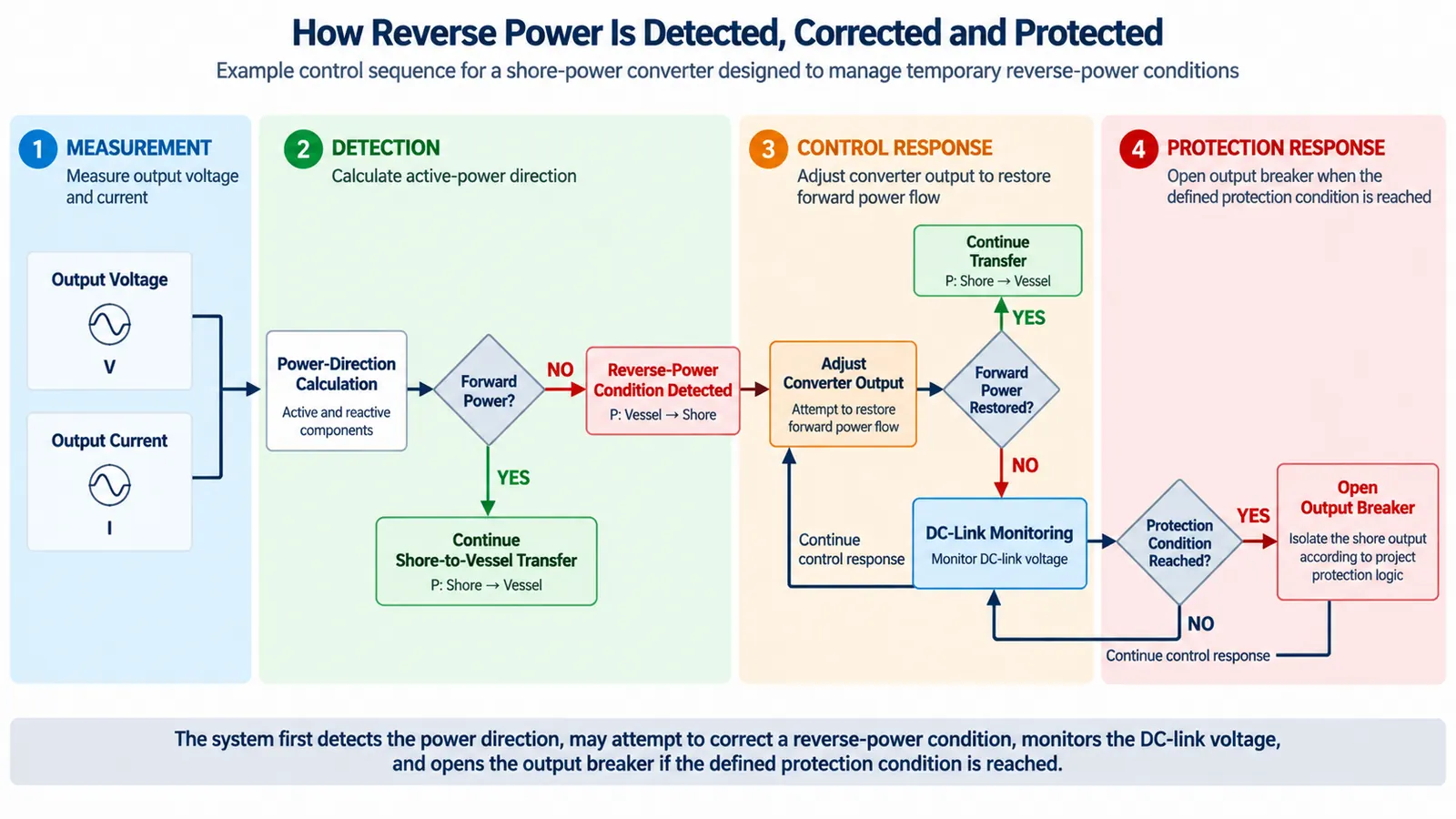
This does not mean every vessel should use synchronized transfer.
A no-break or closed-transition transfer should only be used where the actual vessel electrical system, controls, protection and approved operating philosophy support it.
Otherwise, an open-transition method can provide a simpler electrical boundary at the cost of a temporary interruption.
That is an engineering trade-off, not a universal preference.
For the protection mechanism itself, see shore power reverse power protection .
Emergency Shutdown Starts With an Unsafe Condition
A planned disconnection begins with an operational decision.
An emergency shutdown begins with a hazard or failure condition.
The initiating condition can come from different parts of the system:
- emergency-stop activation;
- electrical protection operation;
- safety or pilot circuit loss;
- loss of protective or equipotential-bond continuity;
- cable or connector abnormality;
- converter or switching-device fault;
- unsafe cable-management condition;
- loss of required ship-to-shore permissives.
The design should first define what unsafe condition has occurred and what safe state must be reached. Only then should it determine which converter functions, breakers, safety circuits and auxiliary systems must act.
Opening every device is not automatically the correct response for every architecture. Neither is stopping only the converter.
The shutdown response should be defined by the safe state required for the specific initiating condition.
A Cause-and-Effect Matrix Makes the Shutdown Philosophy Testable
A shutdown philosophy becomes much easier to design, program and verify when initiating conditions, required actions and evidence of completion are separated.
| Initiating Condition | Engineering Objective | Possible Required Response* | Evidence of Safe State | Reset / Recovery Requirement |
|---|---|---|---|---|
| Planned vessel departure | Controlled transfer and release | Transfer load, stop conversion and isolate the required shore output | Load removed, breaker state confirmed and connection de-energized | Normal cable-release sequence |
| Emergency-stop activation | Remove unsafe electrical condition | Execute the approved emergency trip path | Converter / breaker feedback and emergency status | Cause checked and authorized reset |
| Safety or pilot circuit loss | Remove connection permission | Project-defined safety shutdown | Safety-circuit state plus switching feedback | Circuit integrity restored |
| Protective or bonding path loss | Prevent operation without required protective path | Trip or inhibit according to the applicable architecture | Protective path restored and isolation confirmed | Inspect and restore before reconnecting |
| Protection relay operation | Isolate an electrical fault | Protection clears the defined fault zone | Relay indication plus breaker feedback | Fault investigation and protection reset |
| Cable or connector abnormality | Prevent continued unsafe energization | Remove power through the defined safety path | Connection de-energized and interface isolated | Cable or connector inspection required |
| Breaker open command without open feedback | Detect failure to reach the safe state | Inhibit the next sequence step and escalate | Actual isolation must be independently established | Investigate switching-device failure |
| SCADA communication loss | Preserve local safety | Continue, inhibit start or stop according to the approved cause-and-effect design | Local protection and safety state remain valid | Communication restored and stale data cleared |
*The exact action is project-specific and must follow the applicable standard, system architecture and hazard assessment.
This matrix is not a universal switching procedure.
Its purpose is to show what the project specification needs to define.
Keep Safety Shutdown Separate From Ordinary Supervisory Communication
A modern shore power installation can have extensive remote monitoring and control.
The project engineering material used for this article includes remote breaker control, shore power start, stop and reset, fault information, operating data and historical records.
That does not make SCADA the safety system.
IEC/IEEE 80005-2:2016 covers shore-connection communication for non-emergency functions. Emergency safety functions are treated separately within the applicable shore-connection safety architecture.
For HV shore connections, IEC/IEEE 80005-1 provides the safety framework for protection, monitoring and interlocking, including HVSC safety-circuit requirements.
Safety path acts.
SCADA supervises, displays and records.
A network failure should not silently remove the protection function that the system depends on to reach its safe state.
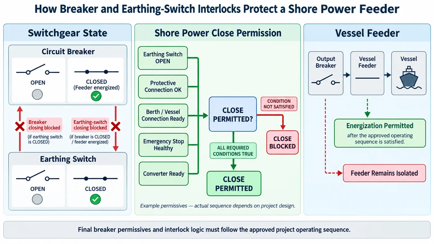
For the wider design of permissives, trips and interlocks, see shore power protection and interlock functions .
HV and LV Systems Share the Principle, Not Every Detail
It is easy to overgeneralize shore power safety requirements.
That should be avoided.
IEC/IEEE 80005-1 applies to high-voltage shore connection systems. IEC/IEEE 80005-3:2025 provides the current international framework for its defined low-voltage shore connection scope.
Both require proper protection, switching, monitoring and interlocking, but the exact circuit design, timing, pilot arrangement and required device actions are not automatically identical.
An HV safety-loop requirement should therefore not simply be copied into an LV cause-and-effect matrix without checking the applicable scope.
A Stop Command Is Not Proof of Electrical Isolation
One of the most important acceptance questions is:
Consider a breaker-open sequence.
The PLC issues the command. The breaker mechanism begins to operate. The control system expects an open-position feedback.
If that feedback never arrives, the system has not proved the required state.
A weak sequence may continue because a timer has expired.
A stronger sequence treats missing feedback as a failed operation and prevents progression toward cable release.
The same principle applies to converter state, pilot continuity, safety circuits and mechanical locking.
What If the Safe State Cannot Be Confirmed?
This is where many simplified explanations of emergency shutdown stop too early.
The project must also define what happens when the intended shutdown does not complete normally.
Breaker Fails to Open
Release permission should not be granted merely because an open command exists.
Contradictory Feedback
The state should be treated as uncertain until the actual electrical condition is resolved.
Pilot / Connector State Disagreement
Energization or release should not continue on the assumption that one signal is correct.
SCADA Communication Lost
Previously displayed values may be stale. Local protection must remain distinguishable from loss of supervision.
Converter Reports Stopped
Downstream isolation still has to be proven before the system reaches the cable-handling state.
Failed Safe-State Confirmation
The failure to achieve a commanded safe state is itself an abnormal condition that needs a defined response.
Cable Release Is a Separate Engineering Permission
The physical cable interface is where control logic becomes personnel safety.
Project testing practice used as engineering experience required cable removal only after all power had been cut off and the cable had been confirmed de-energized.
The wider engineering meaning is:
Converter stopped ≠ electrical isolation
Breaker command ≠ breaker state
Isolation confirmed ≠ cable release permission
The connector and cable-management system may therefore require several conditions before release, depending on the architecture:
- electrical isolation;
- required breaker feedback;
- pilot or safety-circuit condition;
- protective or bonding condition;
- mechanical lock condition;
- authorized operating permission.
Cable Management Can Become an Emergency Input
Cable management is often treated as a mechanical convenience.
In reality, it can become part of the safety logic.
The cable has to tolerate vessel movement caused by tide, loading condition and mooring variation. An abnormal cable condition can affect the connector and the electrical interface.
For A33, the important consequence is that an unsafe mechanical interface can become an electrical shutdown trigger.
Detailed cable travel, reel sizing and mechanical selection remain separate cable-management design questions.
Different Faults Need Different Safe Responses
One generic “trip” indication is not sufficient for system diagnosis or cause-and-effect design.
A loss of shore supply, a vessel-side electrical fault, a safety-circuit loss, a converter fault, an emergency-stop operation and a failed breaker response can all end with shore power unavailable.
But they do not have the same initiating cause, protection path or recovery requirement.
The System Should Preserve the First Useful Evidence
Emergency shutdown should leave the equipment in a safe condition.
It should also leave enough information to explain what caused the event.
Many different initiating conditions can create the same final observation: shore power unavailable.
Useful records can include:
- first-out or initiating alarm;
- protection operation;
- breaker position changes;
- converter state;
- safety-circuit state;
- relevant electrical measurements;
- communication or auxiliary-power failures;
- synchronized timestamps where available.
A reset that immediately clears the initiating evidence can turn a diagnosable problem into a repeated unexplained trip.
The objective is not to collect every possible tag. It is to retain enough evidence to reconstruct the sequence that matters.
Reset Is a Controlled Recovery Step, Not Permission to Energize
A reset can clear a latched protection indication, restore a controller from a faulted state or acknowledge an emergency input after the initiating condition has been removed.
None of those actions proves that reconnection is safe.
If the initiating event involved the cable, the cable should be inspected.
If it involved the safety or pilot circuit, circuit integrity should be re-established.
If a breaker failed to operate, the switching device should be investigated.
If protection operated, the underlying electrical fault should be addressed.
Only after the required permissives have been restored should the normal shore power connection logic become available again.
FAT Should Test the Complete Shutdown Chain
An emergency-stop pushbutton test is not enough.
If the acceptance test verifies only that the input changes state on an HMI, it has not proved the shutdown function.
A serious FAT or SAT review should consider scenarios such as:
- normal planned disconnection;
- emergency-stop input;
- safety or pilot circuit loss;
- relevant protection operation;
- breaker-open feedback failure;
- SCADA or communication loss;
- auxiliary-control-power loss where applicable;
- cable or connection-permissive loss;
- event recording;
- reset authorization;
- reconnection after restoration.
The evidence needs to show that the required downstream state was reached — not only that the initiating input was detected.
For the wider acceptance framework, see our shore power manufacturing and FAT page.
FAT and SAT Do Not Prove Exactly the Same Thing
Factory Acceptance Testing
FAT can verify PLC logic, simulated emergency inputs, relay outputs, converter response, breaker commands, HMI indications, alarm priorities, event records and reset logic in a controlled environment.
Site Acceptance / Commissioning
SAT can confirm installed berth devices, actual field wiring, cable interfaces, ship-shore communication, final breaker interfaces and local operating authority.
A perfect PLC simulation cannot prove that an incorrectly wired field E-stop or pilot contact will operate as intended.
Likewise, a field pushbutton test without controlled cause-and-effect documentation does not prove that the logical failure modes have been tested.
A mature acceptance plan uses both.
Project Evidence: Why Multi-Location Confirmation Matters
The project engineering material behind this article provides a useful example of how the principle appears in practice.
The commissioning organization included a port command function, port operating personnel, equipment engineers and vessel coordination.
Communication equipment was prepared between different working locations, and operating instructions were passed through responsible personnel rather than assumed locally.
The project also used formal shore-power supply and shutdown confirmations and required abnormal situations to be reported and handled through an established command structure.
Where electrical authority is distributed across ship and shore, confirmation itself becomes part of the safety architecture.
Common Design Failures Are Usually Boundary Failures
Many shore power shutdown problems do not begin with the failure of a major power component.
They begin because the boundary between two states or responsibilities was poorly defined.
- A PLC “Stop” indication is mistaken for breaker isolation.
- A remote operator assumes vessel load transfer is complete.
- A connector is treated as mechanically releasable because active power is close to zero.
- SCADA communication loss is displayed as zero instead of stale data.
- A breaker open command has no failed-operation path.
- An emergency reset becomes available before the initiating condition is understood.
- A synchronized transfer is assumed merely because ship and shore nominal voltage and frequency match.
What the Cause-and-Effect Specification Should Define
A useful cause-and-effect document should allow the design engineer, FAT team and operator to answer the same questions.
| Design Field | Question to Answer |
|---|---|
| Initiating condition | What event starts the sequence? |
| Detection point | Which device or signal detects it? |
| Required action | What converter, breaker or safety function acts? |
| Operating authority | Is the action automatic, ship-authorized, shore-authorized or emergency? |
| Expected feedback | What physical state confirms completion? |
| Time / sequence condition | Is timing relevant, and under what applicable requirement? |
| Failed-operation response | What happens if the expected feedback does not arrive? |
| Retained auxiliaries | What must remain powered for safety, control or diagnosis? |
| Alarm / event record | What information must remain available afterward? |
| Reset authority | Who can clear the condition? |
| Reconnection criteria | What must be restored before energization is allowed again? |
This document turns the shutdown philosophy into something that can actually be programmed, tested and accepted.
Information Needed Before the Shutdown Philosophy Is Finalized
Before defining the final cause-and-effect logic, collect:
- shore-side single-line diagram;
- vessel-side single-line diagram;
- shore voltage and frequency;
- vessel operating voltage and frequency;
- normal load-transfer philosophy;
- whether synchronized transfer is supported;
- shore and vessel breaker ownership;
- applicable HVSC or LVSC standard;
- pilot or safety-loop design;
- protective-earth and equipotential-bonding arrangement;
- cable-management interface;
- emergency-stop locations;
- converter stop and trip interfaces;
- protection functions;
- communication architecture;
- retained auxiliary-power requirements;
- required event records;
- reset authority;
- cable-release permissives;
- FAT and SAT acceptance responsibilities.
Without these inputs, a supplier can describe an emergency-stop feature.
It cannot yet define the complete shore power emergency shutdown architecture.
Frequently Asked Questions
Is pressing the Stop button enough before unplugging a shore power cable?
No. A stop command only addresses one part of the operating chain. The relevant switching devices, isolation condition, de-energized state and cable-release permissives still need to be confirmed according to the system architecture.
What is the difference between normal disconnection and emergency shutdown?
Normal disconnection is a planned transition intended to transfer the vessel load and remove shore power in a controlled sequence. Emergency shutdown responds to an unsafe or abnormal condition and prioritizes reaching the required safe state.
Should an emergency shutdown open every breaker?
Not necessarily. The system should first define the required safe state. The applicable standard, SLD, fault zone and cause-and-effect design then determine which devices have to operate.
Can SCADA or Modbus perform the emergency shutdown?
SCADA can monitor status, record events and issue authorized operating commands. Critical emergency functions should follow the applicable safety architecture rather than depend only on ordinary supervisory communication.
What happens if a breaker receives an open command but does not open?
The required safe state has not been confirmed. The sequence should not automatically advance to cable release merely because an open command was issued. The project cause-and-effect logic should define failed-operation detection and escalation.
Can the vessel reconnect immediately after the emergency condition disappears?
Not automatically. The initiating condition should be investigated, affected equipment checked where necessary, the authorized reset completed and the normal connection permissives restored before reconnection.
Do LV and HV shore power systems use the same shutdown logic?
They share many engineering principles, but their applicable requirements are not identical. IEC/IEEE 80005-1 addresses HVSC systems, while IEC/IEEE 80005-3:2025 provides the current international framework for its specified LVSC scope.
Technical References
High-voltage shore connection systems, including design, installation, protection, monitoring, interlocking and HVSC safety requirements.
View IEC reference
Data communication for shore connection monitoring and control, with a stated scope covering non-emergency communication functions.
View IEC reference
Current international standard for its defined low-voltage shore connection scope, including protection, control, monitoring, interlocking and power management.
View IEC reference
Interim Guidelines on Safe Operation of Onshore Power Supply Service in Port for Ships Engaged on International Voyages.
View IMO OPS safety guidance
IACS guidance supporting safe integration and operation of onshore power supply systems.
View IACS Recommendation 182
Define the Safe State Before Defining the Stop Command
A strong shore power emergency shutdown design does not begin with the E-stop pushbutton.
It begins with the safe state.
The project team first defines what must be isolated, what equipment must remain available, what physical feedback proves completion and what conditions permit cable handling.
The normal disconnection sequence and the emergency shutdown sequence can then be developed around those states.
A complete shutdown design should answer four questions:
- What initiated the shutdown?
- What equipment was required to act?
- How do we know the intended safe state was actually achieved?
- What must be restored before the system can be energized again?
Send the shore and vessel SLDs, transfer philosophy, breaker responsibilities, emergency-stop arrangement, pilot or safety-loop logic and cable interface for an engineering review.
Send Your Shutdown Requirements