Microwave Power · Plasma · PCVD · OEM Integration

Microwave Generators for Plasma & PCVD

Integrate controlled microwave power into plasma and PCVD equipment with application-specific generator, microwave-head, waveguide, matching, cooling and control configurations. SDACME supports microwave-source and subsystem integration based on frequency, power, chamber interface, reflected-power conditions and equipment-control requirements.
  • 2.45 GHz Microwave Source
  • 6 / 10 / 15 kW
  • Plasma & PCVD Integration
  • OEM Subsystem Support
Plasma / PCVD Microwave Source
2.45 GHz
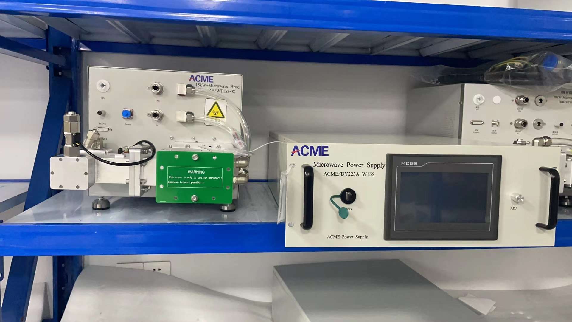
15 kW 2450 MHz microwave generator for plasma and PCVD equipment integration

Microwave Source for Plasma Equipment Integration

2.45 GHz microwave generator configurations can be integrated with the required microwave delivery, matching, cooling and control architecture for plasma and PCVD equipment.

Microwave Source
→
Delivery & Matching
→
Plasma / PCVD Chamber

Generator-only, microwave subsystem and broader equipment supply scopes are confirmed according to the project, chamber interface and agreed technical boundary.

Microwave Power for Plasma Systems

Microwave Power Is One Part of the Complete Plasma System

A microwave generator for plasma supplies microwave energy to a larger plasma or PCVD equipment architecture. Generator selection therefore needs to consider not only nominal power, but also microwave transmission, impedance matching, chamber interface, cooling, control and the behavior of the process load.

01 Source Selection

Frequency and microwave power are selected according to the plasma equipment, required operating range and overall system architecture.

02 System Integration

The generator must be coordinated with the microwave head, waveguide, matching hardware, chamber interface, cooling and equipment control.

01

Required Microwave Power

Define the required operating range and maximum microwave power for the plasma equipment.

02

Power Delivery Interface

Confirm the microwave head, transmission path, flange and chamber-side interface.

03

Process-Side Conditions

Vacuum, gas, chamber and load behavior need to be considered because they affect the complete microwave-delivery system.

Direct Answer

Can a microwave generator determine plasma performance by itself?

No. The generator supplies microwave energy, while plasma performance depends on the complete system, including the chamber, microwave-delivery path, matching, vacuum/gas conditions and process configuration.

Frequency & Power Selection

Select the Microwave Source from the Plasma-System Requirements

SDACME's 2.45 GHz microwave-generator range includes 6 kW, 10 kW and 15 kW configurations. The appropriate source is selected against required microwave power, operating range, chamber interface and overall equipment architecture.

6 kW

2450 MHz

Lower-Power Configuration

Suitable as a 2.45 GHz microwave-source option where the plasma equipment requires a lower microwave power range.

10 kW

2450 MHz

Intermediate Power Configuration

An intermediate 2.45 GHz microwave-source configuration for plasma or PCVD equipment integration.

15 kW

2450 MHz

Higher 2.45 GHz Power

A 15 kW-class microwave source for applications requiring higher power within the published 2.45 GHz product range.

Power Alone Does Not Define the Plasma Process

The selected frequency and power must be considered together with the microwave transmission, matching arrangement, chamber interface, cooling, controls and load conditions. Higher-power or alternative-frequency configurations can be evaluated separately when required by the project.

Microwave System Architecture

From the Microwave Generator to the Plasma Chamber

A plasma microwave subsystem is defined by the complete microwave power-delivery path. This architecture shows the major functional blocks without exposing internal tuning procedures, control logic or project-specific engineering details.

01

Microwave Generator

Provides the selected microwave power for the plasma or PCVD equipment.

02

Microwave Head

Provides the microwave-output interface between the power source and transmission path.

03

Isolation & Monitoring

Supports applicable protection and forward/reflected-power monitoring.

04

Waveguide Transmission

Transfers microwave power toward the chamber or application interface.

05

Impedance Matching

Supports matching between the microwave source and application load where required.

06

Plasma / PCVD Chamber

The process-side load and application interface, reviewed together with vacuum and gas conditions.

Control & Interlocks

Coordinate generator operation with the wider equipment-control architecture.

Cooling

Cooling requirements are confirmed for the selected generator, microwave head and associated components.

Vacuum & Gas Conditions

Process-side operating conditions are project inputs for the complete plasma-system configuration.

Project supply boundary: generator-only, microwave subsystem and broader equipment scopes are confirmed according to the quotation and technical agreement. Plasma-process performance depends on the complete system, not on the microwave generator alone.
Microwave Delivery

Matching, Transmission & Reflected-Power Conditions

The microwave generator is only one part of the RF power path. Depending on the project, the subsystem can include components for transmission, isolation, monitoring and impedance adjustment between the source and the plasma chamber.
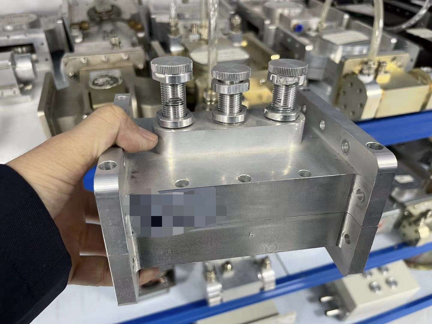
Three-probe impedance tuner for microwave plasma system matching
Example microwave impedance-matching hardware. Final inclusion and interface are confirmed according to the project.

Waveguide Transmission

Waveguide and interface geometry need to be coordinated with the selected microwave source and chamber arrangement.

Isolation & Monitoring

Forward and reflected-power conditions are important engineering inputs when a microwave source is connected to a plasma load.

Impedance Matching

A matching arrangement, including a tuner where applicable, can form part of the microwave-delivery configuration.

Project Integration

The final combination depends on frequency, power, chamber interface, transmission geometry and load behavior.

Detailed tuning procedures, protection thresholds, automatic matching logic and commissioning recipes are project-level engineering information rather than public web specifications.
Application Boundary

Plasma Chamber, Vacuum & Gas Conditions

Plasma generation takes place inside a process environment. The microwave source therefore cannot be selected independently from the chamber and process-side conditions. These inputs are reviewed before the microwave configuration is finalized.

01

Chamber Interface

Confirm connection position, flange or waveguide interface, installation space and relevant chamber geometry.

02

Vacuum Conditions

Provide the basic operating vacuum requirements and relationship between the plasma chamber and vacuum system.

03

Gas Conditions

Provide the process-side gas conditions relevant to equipment integration. Detailed process recipes remain outside the public microwave-source specification.

04

Plasma Load Behavior

The plasma load can affect impedance matching and reflected-power conditions, making complete system evaluation necessary.

Define the Supply Boundary Before Final Configuration

Generator-only, microwave subsystem and broader equipment responsibilities are confirmed according to the quotation, equipment architecture and technical agreement.

Control & Monitoring

Integrate the Microwave Source with the Equipment Control Architecture

Microwave generators used in plasma equipment normally operate as part of a larger machine-control architecture. Applicable functions depend on the selected generator and project scope.

HMI Operation

Local operation and operating-status visibility are available on applicable generator configurations.

Remote Equipment Control

Remote-control requirements can be reviewed when integrating the generator into OEM plasma equipment.

Communication

RS485 and Modbus RTU are documented for applicable models. Other communication requirements are confirmed by model or project.

Equipment Interlocks

Project interlocks can coordinate microwave operation with cooling, chamber and other machine conditions.
Public information describes control categories and integration capability. Register maps, thresholds, terminal assignments and internal control sequences remain project-level information.
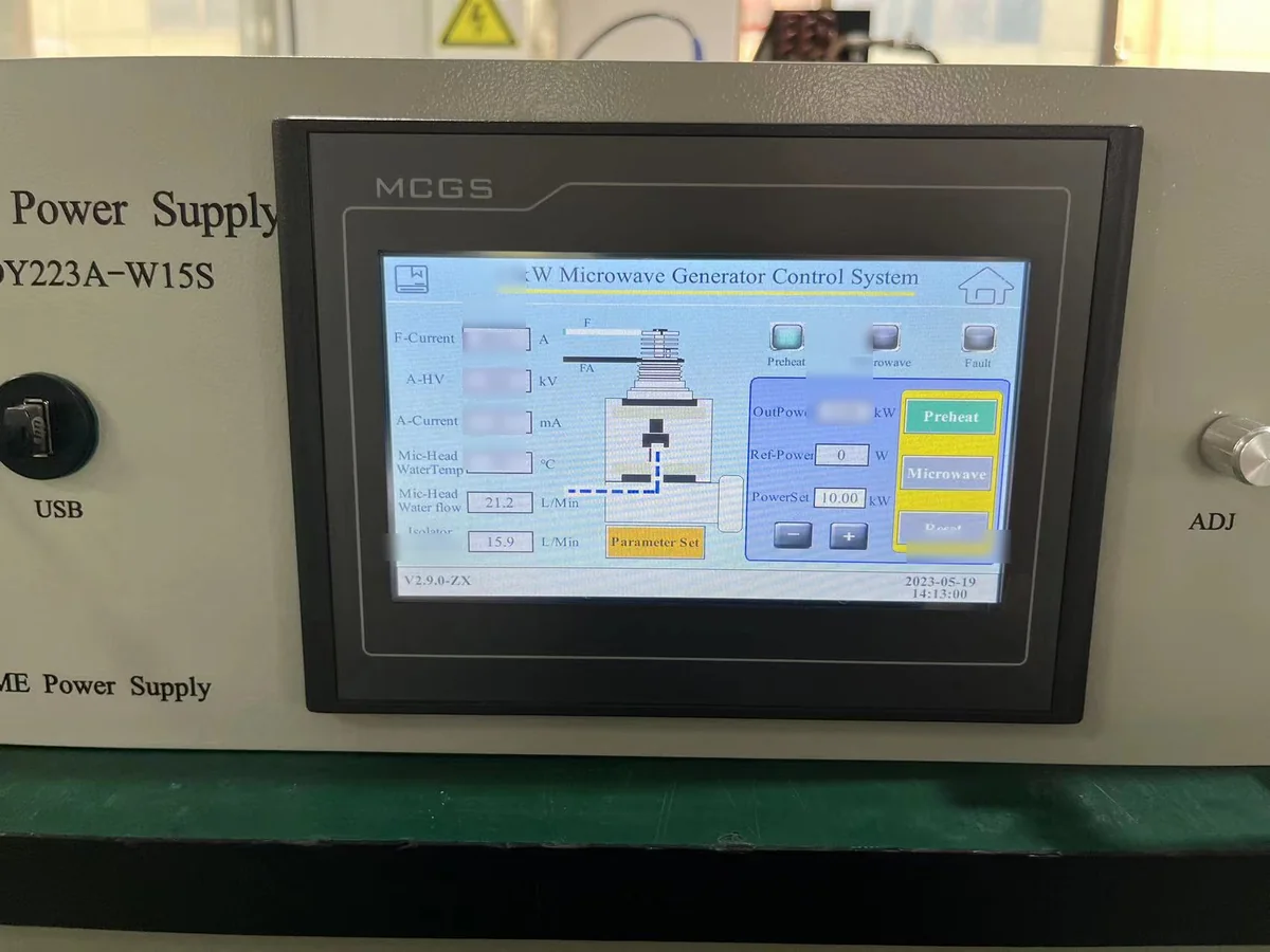
HMI control interface on a 15 kW microwave generator
Example HMI interface on a 15 kW microwave generator. Available screens and functions remain configuration-specific.
Cooling Integration

Cooling Requirements for Plasma Microwave Systems

Cooling is an important part of microwave-generator integration, particularly where the equipment is intended for sustained operation. Required circuits and operating conditions remain model-specific.
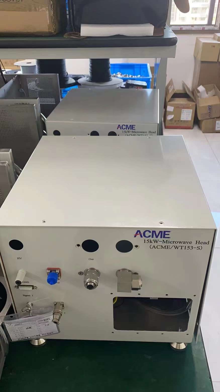
Cooling and interface connections on a 15 kW microwave head
Example cooling and interface connections on a 15 kW microwave-head assembly.
01

Generator Cooling

External cooling conditions must meet the requirements of the selected generator model.

02

Microwave Head Cooling

The microwave head and related RF components may require dedicated cooling connections.

03

Water Conditions

Flow, temperature, pressure and circuit arrangement are confirmed against the selected configuration.

04

Equipment Layout

Cooling connections and service access should be considered during machine layout rather than after installation.

RFQ Engineering Inputs

What We Need for a Plasma / PCVD Project

Provide the project information you already have. These inputs help us select the microwave source, define the integration boundary and identify any missing technical information before quotation.

01

Application

Plasma generation, PCVD or another relevant plasma process.

02

Microwave Frequency

Required frequency or existing equipment frequency.

03

Microwave Power

Required operating range and maximum microwave power.

04

Chamber Information

Chamber type, installation arrangement and process interface.

05

Waveguide / Flange

Existing or required microwave transmission interface.

06

Vacuum & Gas

Basic process-side operating conditions relevant to system integration.

07

Cooling

Available cooling-water conditions and equipment-layout constraints.

08

Control Requirements

Local/remote control, communication and machine interlock requirements.

09

Drawings / Photos

Existing interface drawings, installation photos or microwave-source information.

Have Only Partial Information?

Send the available drawings, equipment information or photos. We can identify the remaining inputs needed for an initial configuration review.

Send Project Data
Factory Verification

Verify the Agreed Microwave Configuration Before Delivery

Verification is defined against the selected generator, subsystem scope and agreed acceptance requirements. Factory testing demonstrates the agreed equipment functions; it is not presented as a guarantee of the customer's plasma-process result.

✓

Configuration Check

Confirm the agreed generator and subsystem components.

✓

Functional Operation

Check basic generator operation and applicable operating-state functions.

✓

Control & Monitoring

Verify agreed control, status and project-interface functions.

✓

Output-Related Verification

Perform agreed measurements under the defined test configuration.

✓

Protection / Interlock Check

Verify applicable protection and interlock functions included in the test scope.

✓

Documentation

Applicable test records, photos, video or other evidence can be prepared according to the project.
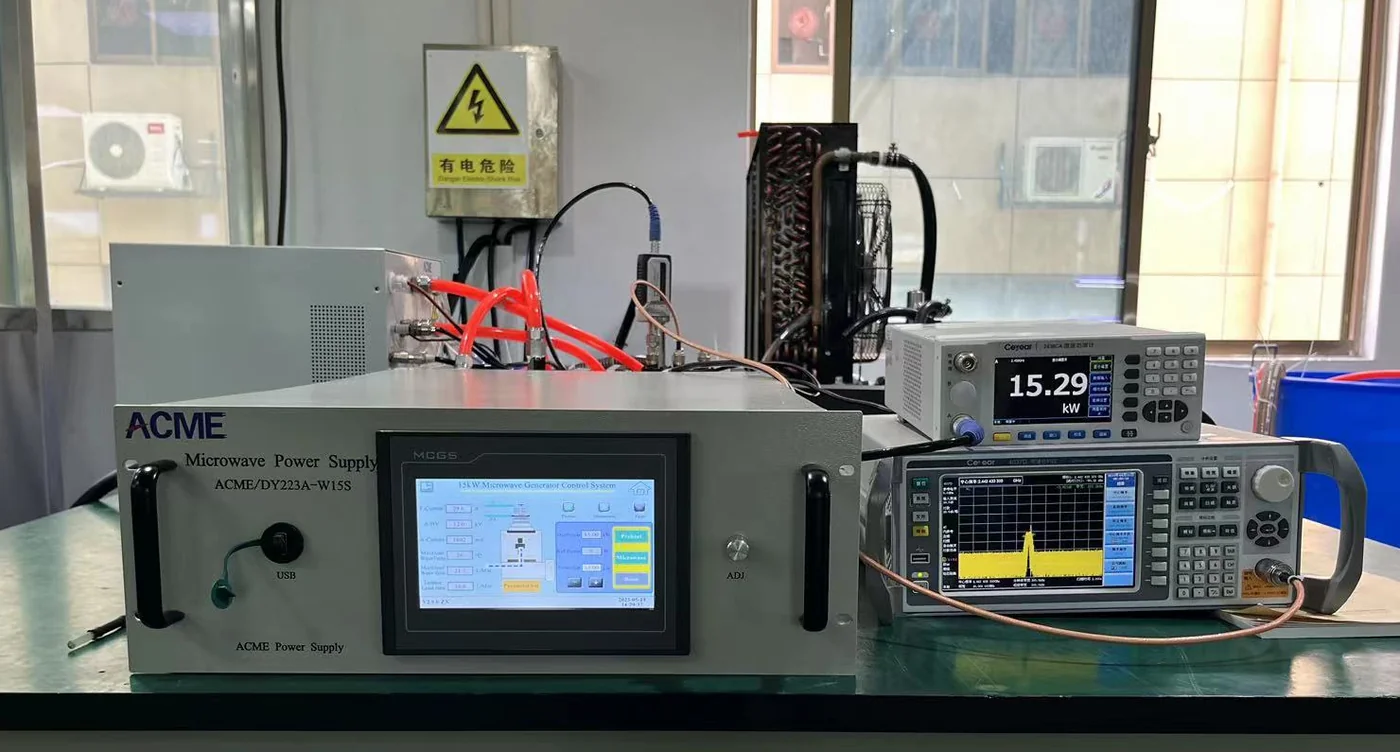
Factory functional testing of a 15 kW microwave generator
Factory functional verification on a 15 kW microwave generator.
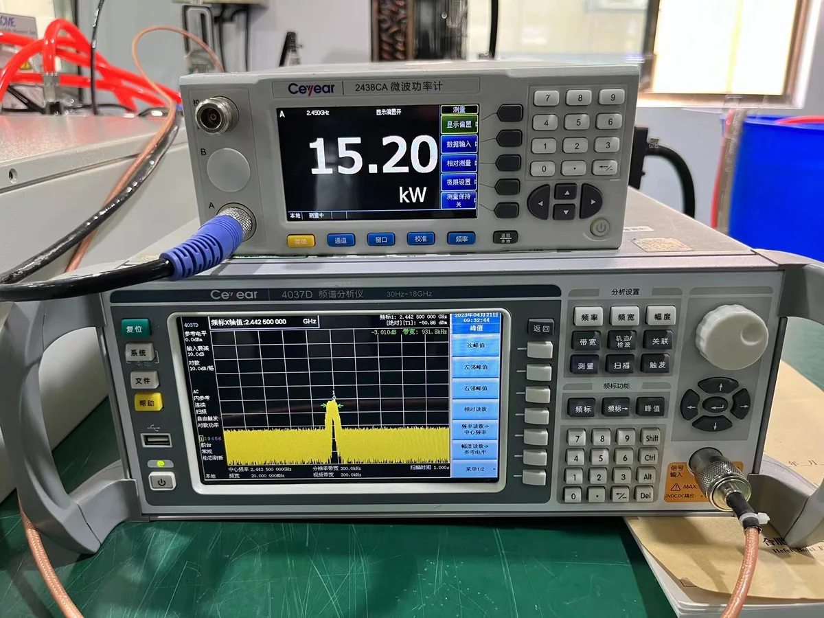
Power and spectrum testing of a 15 kW microwave generator
Example output-related measurement under a defined factory test setup.
FAT items, test conditions, acceptance criteria and records are confirmed according to the applicable generator configuration, supplied equipment and project agreement.
FAQ · GEO Direct Answers

Microwave Generators for Plasma & PCVD — Frequently Asked Questions

Direct answers to common questions from plasma-equipment manufacturers, system integrators and engineers selecting a microwave source.

What is a microwave generator for plasma?

A microwave generator supplies microwave energy to a plasma-processing system. It works together with the microwave head, transmission components, matching arrangement and process chamber rather than operating as an independent plasma process.

What power levels are available for 2.45 GHz plasma equipment?

SDACME's published 2.45 GHz microwave-generator range includes 6 kW, 10 kW and 15 kW configurations. Selection depends on microwave power, chamber interface, cooling, control and the overall equipment architecture.

Can a microwave generator be supplied for PCVD equipment?

Yes. Microwave-source and subsystem configurations can be evaluated for PCVD equipment. The final configuration should be selected according to chamber, waveguide, cooling, control, vacuum/gas and other project requirements.

Is the microwave generator the complete plasma system?

Not necessarily. The microwave generator is the microwave power source. Generator-only, microwave subsystem and broader equipment supply scopes are confirmed according to the project and technical agreement.

Why is reflected power important in a plasma system?

The plasma chamber forms part of the microwave load. Changes in that load can influence matching and reflected-power conditions, so these factors need to be considered when defining the microwave-delivery system.

What information is required before selecting a microwave generator?

Typical inputs include the application, microwave frequency and power, chamber information, waveguide or flange interface, vacuum and gas conditions, cooling conditions, control requirements and available installation drawings or photos.

Can SDACME integrate a microwave source with an existing plasma chamber?

Existing-equipment integration can be evaluated after the chamber interface, waveguide arrangement, frequency, power, cooling and equipment-control conditions are reviewed.

Does the microwave generator guarantee plasma or deposition performance?

No single microwave source determines the complete process result. Plasma stability and process performance depend on the complete equipment and process configuration, including the chamber, microwave-delivery path, matching, vacuum/gas conditions and operating parameters.

Project RFQ

Discuss Your Plasma / PCVD Microwave Project

Whether you need a standalone microwave generator or a microwave subsystem for OEM plasma equipment, the first step is to define the application and integration boundary. Send the information you already have and our team can evaluate an appropriate microwave-source configuration.

Please Include, Where Available

Plasma / PCVD application
Required frequency
Required microwave power
Chamber details
Waveguide / flange interface
Vacuum & gas conditions
Cooling-water conditions
Control / communication
Existing drawings or photos
Requested supply scope

For an existing plasma system, include the current microwave-source information, available interface drawings and equipment photos where possible.
