MICROWAVE GENERATOR SYSTEMS · OEM INTEGRATION

Microwave Generator Systems for OEM Integration

Industrial microwave source systems for 2450 MHz and 915 MHz applications, configured around power level, RF transmission, control, cooling and equipment-interface requirements.

SDACME supports microwave generator supply and project-configured subsystem integration for equipment manufacturers, research platforms and industrial microwave systems. System scope can be defined according to the selected generator, waveguide arrangement, monitoring requirements and OEM interface.
2450 MHz Systems 915 MHz High Power OEM Subsystems Project-Configured Scope
Frequency 2450 MHz / 915 MHz
System Level Generator / OEM Subsystem
Integration RF · Control · Cooling
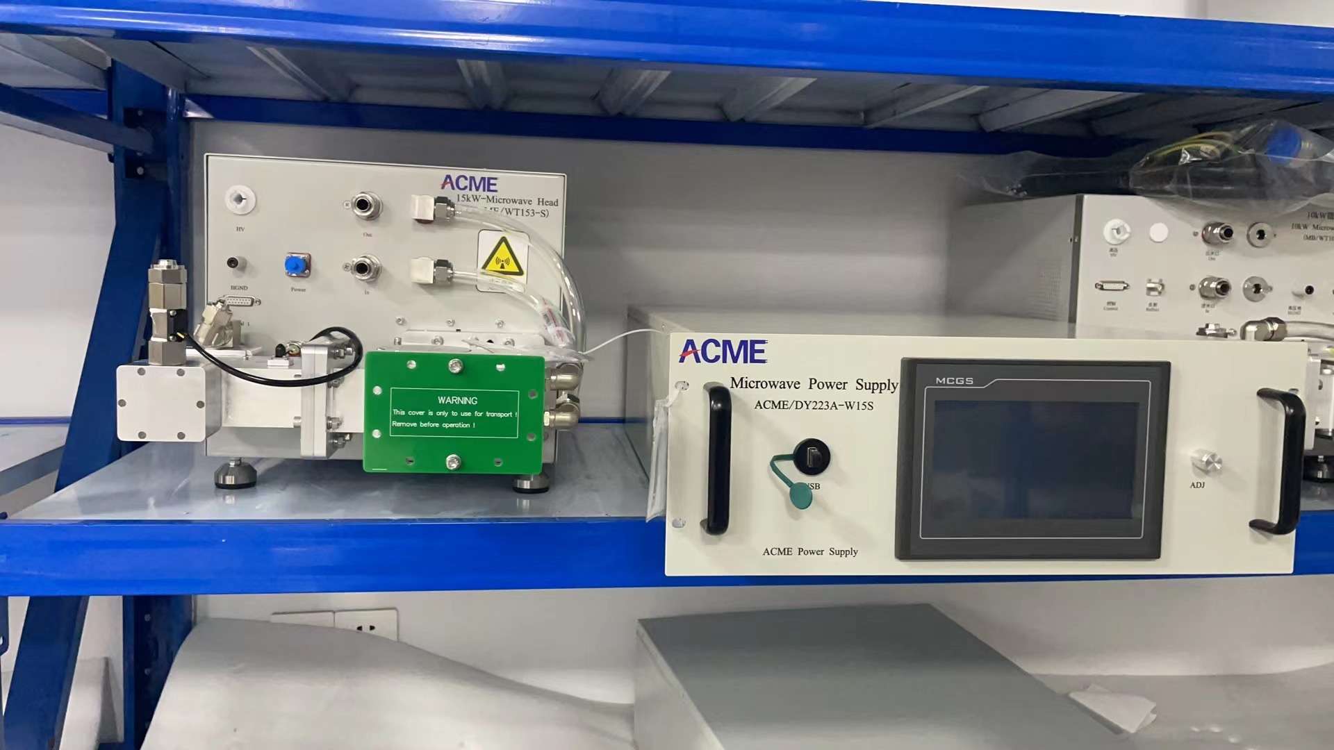
15 kW 2450 MHz industrial microwave generator system for OEM integration
2450 MHz 15 kW Microwave Generator System
System configuration shown
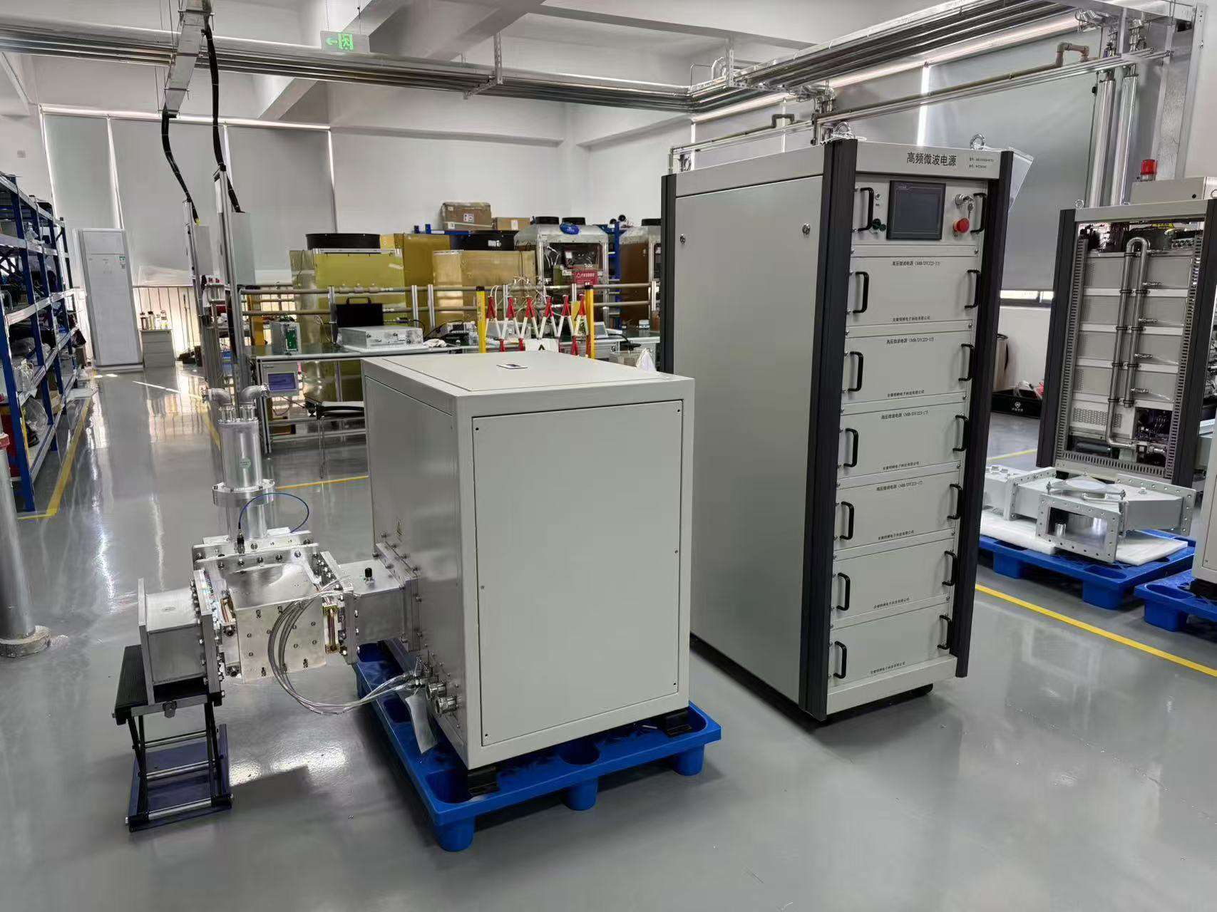
75 kW 915 MHz high power industrial microwave generator system
915 MHz
75 kW High-Power System

High-power microwave generator configuration for industrial system integration.

RF
System scope is configuration-dependent.

RF transmission, monitoring, tuning and control components are confirmed according to the selected model and project.

SYSTEM OVERVIEW

What Is a Microwave Generator System?

A microwave generator system is more than a microwave power supply. It combines the microwave source with the RF transmission, monitoring, control and equipment-interface functions required to deliver microwave energy into an industrial process or OEM machine.

Practical Definition
Microwave Generator System

A project-configured microwave source package built around the generator core and extended, where required, with RF isolation, power monitoring, tuning, waveguide transmission, control interfaces and integration components.

01 Electrical

Microwave Power Supply

Provides and regulates the electrical power required by the microwave source. Depending on the selected generator, the power section can also incorporate operating control, status monitoring and protection functions.

Primary Role Electrical power & control
02 RF Source

Microwave Head / Magnetron

The microwave head contains the RF-generating section, typically centered on the magnetron and microwave-launch structure. It converts electrical power into microwave energy at the specified operating frequency.

Primary Role Microwave generation
03 Generator Core

Microwave Generator

The generator combines the power and control section with the microwave head and the core connections required for operation. It forms the central microwave source around which the wider RF system is configured.

Typical Core Power + control + microwave head
FROM COMPONENT TO SYSTEM

Different terms describe different levels of the microwave supply.

01 Power Supply Electrical power
+
02 Microwave Head RF generation
=
03 Generator Core Microwave source
+
04 RF Integration Project configured
=
05 Generator System OEM subsystem
RF

Define the supply scope around your integration requirements.

Circulators, water loads, directional couplers, tuners, rigid or flexible waveguide and external control interfaces can be selected according to the generator configuration, RF layout and OEM equipment requirements.

SYSTEM ARCHITECTURE

From Electrical Power to Microwave Energy at the Load

An industrial microwave generator system is engineered as a complete RF energy path. The generator creates the microwave power, while isolation, monitoring, matching and waveguide components connect that source to the customer’s applicator, chamber or process load.

Generator Core Microwave source platform
Project-Configured RF Selected around the RF design
Customer Equipment Process-side interface
01 SITE
AC

Site Power

Electrical input is defined according to the selected generator configuration and installation requirements.

02 CORE
PSU

Power & Control

Supplies and regulates the electrical power required by the microwave source and supports generator operation.

03 CORE
RF

Microwave Head

The magnetron-based microwave source converts electrical power into RF energy at the selected operating frequency.

04 RF
ISO

RF Isolation

Circulator, isolator and load arrangements can be selected to manage reflected microwave power in the RF chain.

05 RF
MON

Power Monitoring

Directional coupling can support forward and reflected power measurement where required by the system design.

06 RF
TUNE

Matching & Tuning

Matching components such as a three-stub tuner can be introduced according to the load and RF integration design.

07 RF
WG

Waveguide Run

Rigid or flexible waveguide, bends, transitions and interfaces connect the microwave source to the process equipment.

08 LOAD
OEM

Applicator / Chamber / Load

The microwave system terminates at the customer’s process-side equipment, where RF energy is applied to the intended load.

ZONE A Generator Core

The power/control section and microwave head form the central microwave source platform.

Power & Control Microwave Head Magnetron Source Core Connections
ZONE B Project-Configured RF

RF transmission and integration components are selected according to power, frequency, load and equipment layout.

Isolation / Load Power Monitoring Matching / Tuning Waveguide & Interfaces
ZONE C Process Equipment

The RF system is integrated with the customer’s applicator, chamber or process load and the required site utilities.

Applicator Chamber Process Load Site Interface
RF

Design the generator as part of the complete RF path.

Frequency, power level, reflected-power conditions, waveguide route, load characteristics, control interface and cooling requirements should be evaluated together when configuring an OEM microwave generator system.

NEXT Which components can be included in the supply?
View Supply Scope →
SUPPLY SCOPE

Configure the Supply Around Your Microwave System

A microwave generator system can be supplied at different levels. The generator core provides the microwave source, while RF transmission, monitoring, tuning, controls and mechanical interfaces are selected according to the equipment architecture and project scope.

SCOPE
Define the system boundary before finalizing the configuration.

Frequency, power level, waveguide interface, reflected-power management, control method, cooling arrangement and the connection to the customer’s process equipment all influence the final microwave subsystem scope.

01
GENERATOR LEVEL

Typical Generator Core

The core microwave source platform around which the wider generator system is configured.

Power & Control Section

Electrical power conversion, regulation and generator operating functions.

Microwave Head

Magnetron-based RF generation section matched to the selected operating frequency.

Core Connections

Required connections between the power/control section and microwave head for the selected generator.

02
RF / INTEGRATION LEVEL

Project-Configured Components

Components selected according to the RF layout, power level, load characteristics and OEM equipment requirements.

RF Isolation & Load

Circulator, isolator and water-load arrangements can be configured for reflected-power management.

Power Monitoring

Directional coupling and forward / reflected power monitoring can be integrated where required.

Matching & Tuning

Tuning components can be selected according to the microwave load and RF matching strategy.

Waveguide & RF Interfaces

Rigid or flexible waveguide, transitions, bends and mechanical interfaces can be configured for the RF route.

OEM Control Interfaces

Communication and external equipment interfaces are defined according to the selected generator and project.

03
PROCESS / SITE LEVEL

Equipment & Site Interface

The microwave subsystem must be matched to the process equipment and facility conditions defined for the project.

Applicator / Chamber

RF output connects to the process-side applicator, chamber or other microwave load.

Process Load

Load geometry and operating conditions influence RF transmission and matching decisions.

Site Electrical Interface

Available electrical supply and installation conditions are confirmed during project definition.

Cooling & Utilities

Cooling connections and other facility-side utilities are coordinated with the selected equipment configuration.

Machine-Level Interlocks

Required safety and operating interlocks are defined according to the agreed OEM integration architecture.

SCOPE AT A GLANCE

One system can be supplied at different integration levels.

System Element
Generator Core
Project Configured
Process / Site Interface
Power & Control
Core
—
Electrical connection
Microwave Head
Core
—
RF load interface
Isolation / Monitoring
—
By Configuration
Load conditions
Matching / Tuning
—
By Configuration
Load / process dependent
Waveguide System
—
By Configuration
Equipment connection
Applicator / Process Equipment
—
Agreed project scope
Project Interface
TO DEFINE THE SCOPE

Provide the main system interfaces before quotation.

Early interface information helps define which parts belong in the microwave subsystem and which connect to the OEM machine.

01 Operating Frequency 2450 MHz or 915 MHz platform
02 Required Power Target microwave power level
03 Load / Chamber Process-side RF load information
04 Waveguide Interface Flange, route and mechanical layout
05 Control Interface Local, remote or machine integration
06 Site Conditions Electrical and cooling interfaces
OEM

Request the system level you actually need.

SDACME can define the microwave source and integration scope around the selected generator and OEM equipment requirements. The proposal can therefore focus on the interfaces and RF components needed for the specific machine architecture, rather than assuming the same component package for every project.

NEXT See the power supply and microwave head that form the generator core.
View Generator Core →
GENERATOR CORE

Power Supply + Microwave Head: The Core Microwave Source

The core microwave generator combines the electrical power and control section with the microwave head that generates RF energy. These two functions work together as the central source platform before project-specific transmission, monitoring and matching components are added.

10 kW 2450 MHz microwave generator power supply cabinet and microwave head
2450 MHz Example Power Supply Cabinet + Microwave Head 10 kW configuration shown
TWO CORE FUNCTIONS

Electrical conversion and RF generation are separate, but engineered as one source.

The power section provides the electrical conditions and operating control required by the microwave source. The microwave head contains the RF-generating section, centered on the magnetron and its microwave-launch structure.

For OEM integration, both sides must be reviewed together: the electrical and control interfaces on one side, and the RF, cooling and mechanical interfaces on the other.

01 Power & Control Drives and regulates the microwave source
02 Microwave Head Converts electrical input into microwave energy
03 Core Connections Electrical, control and generator-side interfaces
PSU
ELECTRICAL SIDE

Microwave Power Supply

Provides the controlled electrical power required for magnetron operation and generator management.

  • Power conversion Converts the available electrical input into the conditions required by the selected microwave source.
  • Power regulation Supports adjustment and regulation of microwave-source operation according to the generator design.
  • Operating control Provides the generator-side control functions available on the selected configuration.
  • Status & protection Monitoring and protection functions are implemented according to the selected model and system design.
RF
MICROWAVE SIDE

Microwave Head

Contains the microwave-generating section that converts controlled electrical power into RF energy.

  • Magnetron source Generates microwave energy at the operating frequency specified for the selected generator.
  • RF output structure Couples the generated microwave energy into the downstream RF transmission path.
  • Cooling interface Cooling requirements are matched to the selected microwave head and system configuration.
  • Mechanical / RF interface The downstream waveguide and equipment interface must be coordinated with the project RF layout.
CORE GENERATOR PATH

The generator core sits between site power and the RF system.

INPUT Site Electrical Power Project interface
→
CORE 01 Power & Control Electrical conversion
→
CORE 02 Microwave Head RF generation
→
OUTPUT RF Transmission System Project configured
OEM INTEGRATION CHECK

Review both sides of the generator core.

A generator cannot be selected only from its rated microwave power. The electrical, control, cooling, mechanical and RF interfaces must match the equipment into which the source will be integrated.

01 Electrical Input Site voltage, frequency and capacity
02 Control Requirement Local, remote or machine-level integration
03 Cooling Interface Generator and microwave-head cooling arrangement
04 RF Interface Frequency, waveguide and downstream load
OEM

Specify whether you need the generator core or a wider RF subsystem.

If your machine already has waveguide, matching or process-side equipment, SDACME can review the interface around the required microwave source. For a new OEM design, additional RF transmission, monitoring and integration components can be defined as part of the system proposal.

NEXT See how isolation, monitoring and tuning components extend the generator core.
View RF Components →
RF COMPONENTS

Isolation, Monitoring & Matching Around the Microwave Source

The microwave generator core creates RF power, but the downstream system must also manage how that energy travels toward the load and how reflected energy returns through the RF chain. Isolation, monitoring and tuning components are therefore selected around the generator, waveguide route and process equipment.

RF ENERGY PATH

Configure the RF chain around both forward and reflected power.

SOURCE
RF
Microwave Head RF generation
→
PROTECTION
ISO
Circulator / Isolator Reflected-energy path
→
MONITORING
MON
Directional Coupling Forward / reflected information
→
MATCHING
TUNE
Tuner RF matching adjustment
→
PROCESS
OEM
Applicator / Load Customer equipment
← REFLECTED POWER

Reflected-power conditions depend on the load, applicator, matching state and complete RF arrangement.

ISO
RF ISOLATION

Circulator / Isolator

Used in the microwave transmission chain to provide isolation and help route reflected microwave energy away from the source.

SYSTEM FUNCTION Reflected-energy management
SCOPE

Selected according to generator model, power level and RF system configuration.

LOAD
ENERGY ABSORPTION

Water Load

Provides an RF energy-absorption path in microwave systems where reflected energy is directed through the isolation chain.

SYSTEM FUNCTION Microwave energy absorption
SCOPE

Inclusion depends on the selected generator and reflected-power strategy.

MON
RF MONITORING

Directional Coupler

Supports RF monitoring by coupling a controlled portion of the microwave signal for forward- and reflected-power measurement where configured.

SYSTEM FUNCTION Forward / reflected monitoring
SCOPE

Monitoring architecture and measurement functions are confirmed by model and project.

TUNE
RF MATCHING

Three-Stub Tuner

A tuning component used to adjust the microwave transmission system for improved matching between the source, waveguide arrangement and connected load.

SYSTEM FUNCTION RF impedance matching
SCOPE

Evaluated as a project-configured component according to the RF system.
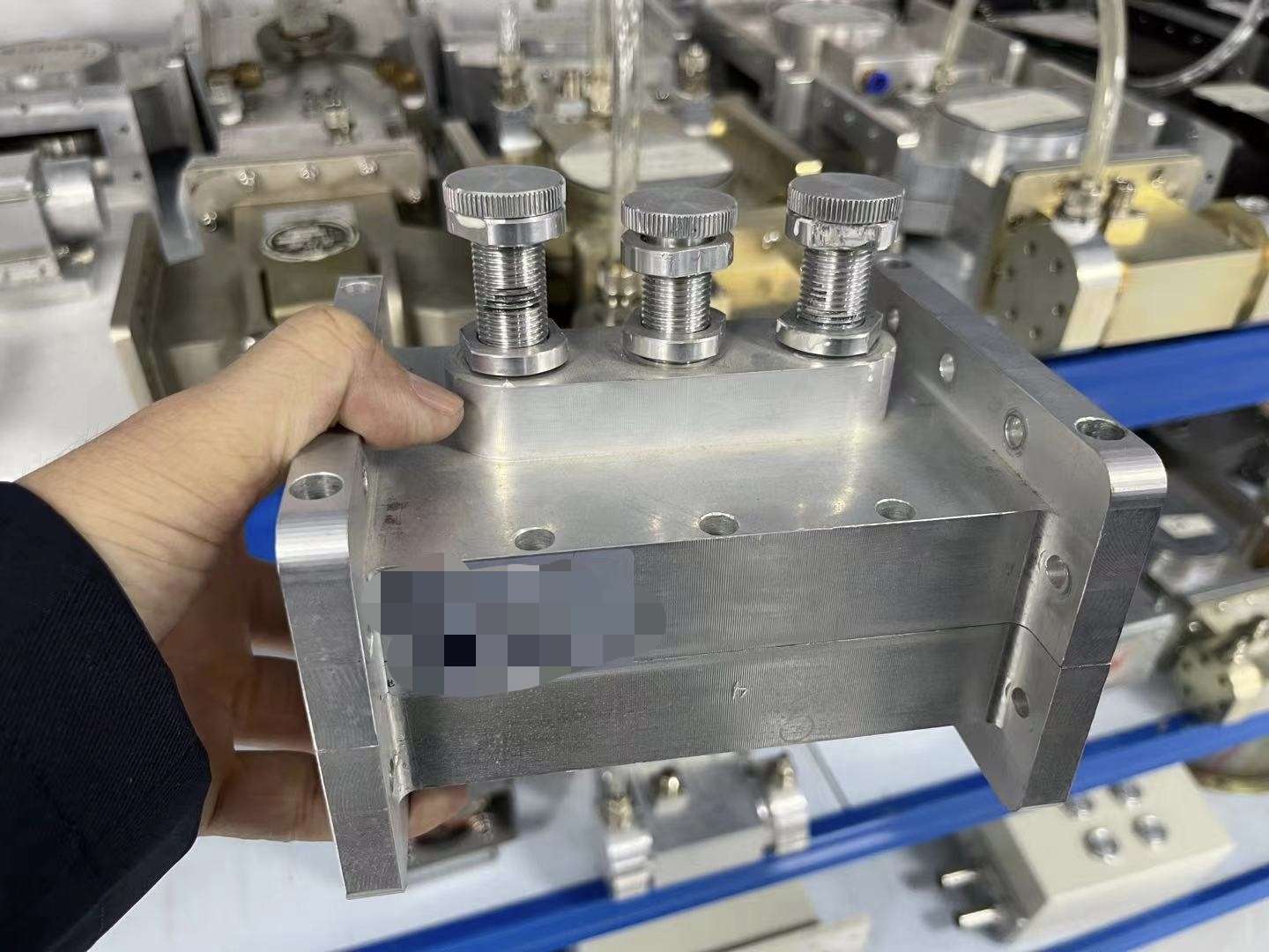
Industrial microwave waveguide three-probe impedance tuner for RF matching
RF MATCHING COMPONENT Waveguide Three-Probe Impedance Tuner
MATCHING THE RF SYSTEM

Tuning is evaluated together with the load and waveguide path.

The microwave generator, tuner and process load do not operate as independent components. The RF behavior is influenced by the waveguide route, chamber or applicator interface and the electrical characteristics of the connected load.

For new OEM equipment, matching requirements can be reviewed during system design. For an existing machine, interface drawings, waveguide dimensions and load information help determine whether additional tuning or RF changes are required.

01 Load Conditions Review the applicator, chamber or connected RF load.
02 Waveguide Geometry Route, flange and transitions affect the complete RF path.
03 Reflected Power Evaluate the expected return-energy conditions.
REFLECTED-POWER MANAGEMENT

Protection starts with the complete RF design.

Reflected-power monitoring and isolation components help manage abnormal or changing load conditions, but the RF system should still be designed around the applicator, chamber, matching condition and expected operating range.

A Generate Microwave head produces forward RF power.
B Deliver Waveguide transfers energy toward the load.
C Monitor Forward and reflected information can be monitored.
D Manage Isolation and matching are configured around the RF system.
RF CONFIGURATION INPUTS

What information helps define the RF component package?

01 Frequency 2450 MHz or 915 MHz system platform
02 Microwave Power Selected generator power class
03 Existing Waveguide Type, flange, route and dimensions
04 Applicator / Chamber Process-side RF connection
05 Load Conditions Expected operating and reflected-power conditions
06 Installation Layout Space, orientation and component arrangement
RF

Select RF components as part of the complete microwave system.

Circulators, isolators, water loads, monitoring components and tuners are matched to the selected frequency, power level, waveguide arrangement and equipment load. The required combination is defined during system configuration rather than assumed from generator power alone.

NEXT Define how the microwave source connects to your equipment.
Review Waveguide Integration →
WAVEGUIDE & RF INTEGRATION

Connect the Microwave Source to Your Equipment

Waveguide integration defines the physical RF path between the microwave generator and the applicator, chamber or process load. Frequency, flange interface, route geometry, transitions, installation space and load conditions should be reviewed together before the transmission system is finalized.

GENERATOR-TO-LOAD PATH

Treat the waveguide run as part of the complete RF system.

SOURCE
RF
Microwave Head Generator RF output
→
RF CHAIN
ISO
RF Components Isolation / monitoring / tuning
→
TRANSMISSION
WG
Waveguide Run Straight sections / bends / transitions
→
INTERFACE
FLG
Equipment Interface Flange / transition / connection
→
PROCESS
OEM
Applicator / Chamber Process-side microwave load
RF INTEGRATION CHECKS

Six interfaces should be defined before the waveguide layout is released.

01 Frequency

The waveguide system and RF components must correspond to the operating-frequency platform selected for the generator.

2450 MHz / 915 MHz
02 RF Interface

Confirm the generator-side and equipment-side connection dimensions before selecting adapters or transitions.

Flange · Transition · Adapter
03 Waveguide Route

Define the distance and physical route between the microwave source and process equipment before finalizing the RF layout.

Length · Bends · Orientation
04 Mechanical Space

Allow installation and service space for the microwave head, RF components, waveguide sections and connection hardware.

Layout · Access · Clearance
05 Process Load

Applicator, chamber and load characteristics influence the RF behavior of the complete generator-to-load transmission path.

Chamber · Applicator · Load
06 Reflected Power

Reflected-power conditions should be considered together with matching, isolation and the expected operating range of the load.

Monitor · Match · Manage
WAVEGUIDE CONFIGURATION

Build the RF route around the machine layout—not the other way around.

The appropriate waveguide arrangement depends on where the generator is installed relative to the process equipment. Straight sections, bends, flexible sections, transitions and matching components can be combined according to the mechanical and RF requirements of the project.

For OEM equipment, reviewing the machine layout early helps reduce unnecessary transitions and makes space available for service, cooling connections and RF components.

A
Straight Run Direct transmission where equipment geometry permits.
B
Bend / Direction Change Routes RF around the equipment structure.
C
Flexible Section Can support selected installation and alignment requirements.
D
Equipment Interface Final connection to the chamber or applicator.
INTEGRATION PATH

New OEM machine or existing equipment?

The required engineering information is different depending on whether the RF system is being designed from the beginning or connected to an existing machine.

NEW DESIGN

OEM Equipment Integration

The generator and RF route can be coordinated with the machine layout before the equipment design is finalized.

  • Generator position
  • Microwave-head orientation
  • RF component space
  • Waveguide path
  • Applicator / chamber connection
  • Service and cooling access
OBJECTIVE Design the RF path with the machine
EXISTING MACHINE

Existing Equipment Integration

Existing RF interfaces should be documented before the replacement or additional microwave source is configured.

  • Existing frequency and power
  • Waveguide type and dimensions
  • Flange and connection details
  • Existing RF components
  • Available installation space
  • Photos / drawings of the interface
OBJECTIVE Match the new source to the existing RF interface
INTERFACE REVIEW

What should be confirmed for an OEM waveguide connection?

Interface
Information to Provide
Why It Matters
Frequency
Required operating-frequency platform
Defines the RF transmission system family
Microwave Power
Required generator power level
Influences RF component and integration selection
Flange / Connection
Drawing, dimensions or clear interface photo
Confirms mechanical RF compatibility
Waveguide Route
Length, bends, orientation and installation space
Defines the physical RF transmission path
Applicator / Load
Chamber or applicator information
Supports matching and reflected-power evaluation
Existing Components
Circulator, tuner, coupler and waveguide details
Helps define what can remain and what should be changed
SEND US YOUR RF INTERFACE

Drawings are usually more useful than a long description.

For an existing machine, interface drawings, waveguide dimensions and clear photos of the current RF connection help define the generator-to-equipment interface. For a new machine, a preliminary layout showing the generator, chamber and available installation space is enough to begin the integration review.

01 Equipment Layout Generator and chamber positions
02 Interface Drawing Flange and mechanical dimensions
03 Existing Photos Current waveguide and RF components
04 RF Requirements Frequency, power and load information
WG

Evaluate waveguide compatibility as a complete RF interface.

Matching one flange dimension is only part of the integration. The operating frequency, power level, waveguide route, existing RF components, applicator and expected load conditions should be reviewed together when connecting a microwave generator to OEM or existing equipment.

NEXT Connect generator operation to your HMI, PLC or machine controls.
Review Controls & Interface →
CONTROLS & OEM INTERFACE

Connect the Generator to Your Machine Control System

An OEM microwave generator must coordinate with the machine’s operating sequence, power command, status monitoring, safety interlocks and fault handling. Control interfaces are therefore defined around the selected generator and the customer’s PLC, HMI or supervisory control architecture.

CONTROL ARCHITECTURE

Local operation and machine-level control can work together.

The generator controller manages microwave-source operation, while the OEM machine can exchange commands, operating status, alarms and interlock conditions through the agreed interface.

Exact signal definitions, register maps, analog ranges and fault-handling logic are confirmed for the selected generator and project configuration.

LOCAL
HMI
Power SET
Status RUN
Alarm MON
Local HMI Start / stop · power setting · status
GENERATOR
CTRL
Generator Controller Power · monitoring · alarms · interlocks
OEM
PLC I/O
Machine PLC Commands · status · safety sequence
CTRL
01 · CONTROL

Generator Operation

Generator controls manage operating mode, microwave output and coordination with the connected equipment.

  • Local touchscreen / HMI operation
  • Local / remote operating mode
  • Start / stop command
  • Adjustable microwave power
  • External machine-control integration
MON
02 · MONITORING

Operating Status

Available operating information can be used by the local HMI or transferred to the machine-control system according to the selected configuration.

  • Microwave power / setpoint information
  • Forward / reflected-power information
  • Electrical operating values
  • Temperature / cooling status
  • Alarm and fault information
SAFE
03 · PROTECTION

Fault & Interlock Handling

Protection logic supervises generator and system conditions and coordinates the appropriate alarm or shutdown response.

  • Electrical input / overcurrent conditions
  • Reflected-power abnormalities
  • Arc / abnormal-load conditions
  • Temperature and cooling conditions
  • Emergency stop / external interlocks
CONTROL INTERFACES

Choose the interface around the OEM machine architecture.

The exact control package is confirmed before the technical agreement so that the generator and machine use compatible commands, signals and communication methods.

Interface
Typical Use
Configuration Approach
Local HMI
Start / stop, power setting, operating status and alarms
Generator Control
RS485 / Modbus RTU
Machine communication and operating-data exchange
Supported Platform
0–10 V / 4–20 mA
Analog power command or feedback where required
By Configuration
Dry Contact / Digital I/O
Run, fault, start / stop and interlock signals
Optional / Project
Ethernet / Network Control
Supervisory or machine-network communication
Confirm by Project
External PLC Integration
Machine sequence, interlocks and coordinated operating logic
OEM Integration
OEM SIGNAL FLOW

Define what the machine sends—and what the generator returns.

A useful OEM control specification separates commands, operating feedback, alarms and safety interlocks instead of treating the communication interface as a single connection.

MACHINE → GENERATOR
Start / Stop
Power Command
Enable / Interlock
⇄ OEM
Interface
GENERATOR → MACHINE
Run / Ready
Power / Status
Alarm / Fault
PROTECTION LOGIC

Fault handling should match the complete machine sequence.

01 Detect Electrical, RF, temperature, cooling or interlock condition
→
02 Evaluate Generator controller evaluates the configured fault condition
→
03 Respond Alarm, power reduction or output shutdown as configured
→
04 Report Fault information is presented to the operator or machine control
CONTROL REQUIREMENTS

Tell us how your machine should communicate with the generator.

01 Operating Mode Local, remote or combined operation
02 Power Command HMI, communication or external signal
03 Communication RS485, Modbus or required machine interface
04 Status Signals Ready, run, power, alarm and fault information
05 Interlock Chain Machine safety and generator enable conditions
06 Fault Handling Required machine response after generator faults
PLC

Confirm the control interface before releasing the OEM electrical design.

For PLC integration, provide the required command method, run and fault signals, communication protocol, interlock sequence and emergency-stop logic. SDACME can then define the generator-side interface for the selected configuration and provide the corresponding signal or communication information for integration.

NEXT Prepare the cooling, electrical and installation conditions for the system.
Review Site Requirements →
COOLING & SITE INTEGRATION

Prepare the Utilities Around the Microwave Generator System

Reliable OEM integration depends on more than the microwave source. Electrical capacity, cooling conditions, grounding, equipment position, waveguide routing and maintenance access should be defined before the generator configuration and installation layout are finalized.

PRE-INSTALLATION OVERVIEW

Four site interfaces surround the microwave source.

01
AC
Electrical Voltage · frequency · capacity · protection · grounding
→
02
H₂O
Cooling Capacity · circuits · flow · temperature · water quality
→
03
LOC
Installation Cabinet · microwave head · clearance · route
→
04
SAFE
Interlocks Cooling · equipment · emergency-stop coordination
COOLING SYSTEM

Size the cooling system for the selected generator configuration.

Microwave generator systems require cooling conditions matched to the selected power level and equipment architecture. The number of cooling circuits, connection points, required flow, temperature, pressure and water quality are confirmed by model and project.

Cooling capacity should be reviewed together with ambient conditions, piping length, pressure losses, condensation margin and the operating duty of the equipment.

Cooling data belongs to the selected configuration. Do not size the chiller from a generic generator-family flow value.
SITE
CHILLER

Cooling-Water Source

Capacity matched to configuration
SUPPLY →
SYSTEM

Cooling Distribution

Circuit arrangement by model / project
→ EQUIPMENT
LOAD
MW
RF

Generator / Head

Required cooling connections
← RETURN WATER
COOLING DATA TO CONFIRM

Review the complete cooling loop before installation.

01 Cooling Capacity

Available chiller or plant cooling capacity for the selected generator configuration.

02 Circuit Arrangement

Number of cooling circuits and required generator-side connection points.

03 Water Flow

Required flow is confirmed from the selected model and cooling architecture.

04 Temperature

Supply-water temperature and condensation margin should suit the site conditions.

05 Pressure

Available pressure should account for piping, fittings and pressure loss.

06 Water Quality

Water-quality requirements are specified according to the equipment configuration.

AC
ELECTRICAL INTERFACE

Site Power & Grounding

Confirm the available electrical supply before the generator power section and upstream distribution are finalized.

  • Voltage & frequency Confirm the site supply available for the selected configuration.
  • Electrical capacity Verify sufficient upstream capacity for generator operation.
  • Protective devices Coordinate the generator with the agreed upstream protection.
  • Grounding Define the protective grounding and equipment-bonding arrangement.
LOC
MECHANICAL INTERFACE

Equipment Position & Access

Cabinet position, microwave-head location and RF route should leave enough space for installation, operation and maintenance.

  • Cabinet location Confirm available floor or mounting space and cable access.
  • Microwave-head position Coordinate orientation with the RF and cooling interfaces.
  • Waveguide / cable route Define routing before finalizing the equipment arrangement.
  • Maintenance clearance Preserve access for inspection, service and connection work.
INSTALLATION LAYOUT

Plan the equipment positions before releasing the final RF layout.

The power cabinet, microwave head, RF transmission line, process equipment and cooling connections form one installation layout. Their relative positions affect cable lengths, waveguide routing, access and utility connections.

01 Power Cabinet Site power + control
CABLE
02 Microwave Head RF + cooling interface
WG
03 Process Equipment Applicator / chamber / load
External Cooling Cooling-water supply and return connect according to the selected equipment configuration.
SITE CONDITIONS

Include ambient and piping conditions in the installation review.

TEMP Ambient Conditions

Review room conditions and their effect on equipment cooling and condensation risk.

AIR Ventilation & Clearance

Keep equipment areas accessible and provide appropriate surrounding clearance.

PIPE Pipe Routing

Plan supply and return lines, fittings and connection points around the machine layout.

DRAIN Drainage

Consider drainage and service requirements associated with the cooling installation.

COOLING INTERLOCK

Coordinate abnormal cooling conditions with generator operation.

Cooling status can form part of the machine and generator interlock chain. The final logic should reflect the selected generator, cooling arrangement and OEM equipment sequence.

01 Cooling Available
→
02 Interlock Healthy
→
03 Microwave Enable
PRE-INSTALLATION DATA

Send these site conditions with your system inquiry.

This information helps define the generator interfaces, cooling arrangement and installation scope before quotation.

01 Site Voltage Available voltage and frequency
02 Electrical Capacity Available upstream power capacity
03 Cooling Source Chiller or plant-water information
04 Cooling Conditions Flow, temperature, pressure and water quality
05 Equipment Layout Cabinet, head and chamber locations
06 Waveguide Route Distance, orientation and installation path
07 Ambient Conditions Room environment and condensation considerations
08 Maintenance Access Required equipment service clearance
SITE

Confirm which site utilities are included in the project scope.

External chillers, plant cooling-water piping, facility electrical distribution and process equipment should be listed explicitly in the quotation or technical agreement when they are part of the required supply. This keeps the generator interfaces and site-preparation responsibilities clear before installation.

NEXT Turn your application and interface data into an OEM system configuration.
View OEM Integration Process →
OEM INTEGRATION PROCESS

From Application Requirements to an Integration-Ready Microwave System

OEM microwave integration is most efficient when the generator, RF path, controls, cooling and equipment interfaces are defined together. SDACME uses the project requirements to establish the microwave source configuration and the interfaces needed for integration with the customer’s machine.

OEM
SYSTEM ENGINEERING PRINCIPLE

Start with the machine interface—not only the generator power.

The required microwave power is only one part of the selection. Frequency, RF connection, control architecture, cooling conditions, installation space and the intended supply boundary should be reviewed before the final system configuration is released.

8-STEP OEM WORKFLOW

Define the interfaces before the system is built.

Each stage reduces uncertainty between the microwave source and the OEM machine.

01 REQUIREMENTS
APP

Application Requirements

Define the machine, process load, required microwave function, operating conditions and expected system duty.

OUTPUT Initial system requirement
→
02 SOURCE
RF

Frequency & Power

Select the microwave-source platform around the required operating frequency and microwave power level.

OUTPUT Generator platform
→
03 RF PATH
WG

RF Interface

Review waveguide, flange, RF components, route geometry and the interface to the applicator or chamber.

OUTPUT RF integration concept
→
04 CONTROL
PLC

Controls & Interlocks

Define local / remote operation, machine commands, communication, operating feedback and safety interlocks.

OUTPUT OEM control interface
05 UTILITIES
H₂O

Cooling & Site Conditions

Confirm electrical supply, cooling arrangement, installation environment and equipment locations.

OUTPUT Site interface requirements
→
06 SCOPE
SOW

Scope Review

Confirm which generator, RF, control and integration components are included in the agreed project supply.

OUTPUT Defined supply boundary
→
07 VERIFICATION
FAT

Testing & Verification

The agreed generator and subsystem functions are checked according to the selected configuration and project requirements.

OUTPUT Verified system configuration
→
08 HANDOFF
OEM

Delivery & Integration

The microwave subsystem is delivered with the agreed interfaces for connection to the OEM machine and site utilities.

OUTPUT Integration-ready subsystem
STARTING INFORMATION

You do not need a finished machine design to start the discussion.

A preliminary machine layout and the main microwave requirements are usually enough for an initial OEM review. More detailed electrical, control, cooling and RF-interface information can then be confirmed as the project develops.

01 Application What the microwave source must do
02 Frequency & Power Required platform and microwave output
03 Equipment Layout Generator, chamber and available space
04 RF Interface Waveguide, flange or existing connection
05 Control Requirement HMI, PLC, signals or communication
06 Site Utilities Electrical and cooling conditions
SCOPE REVIEW

Convert the machine requirements into a clear supply boundary.

The final proposal should make it clear which elements belong to the microwave subsystem and which interfaces connect to the customer’s equipment or site.

A

Microwave Source

Generator power/control section, microwave head and associated core connections.

Core generator
B

RF Integration

Isolation, monitoring, tuning, waveguide and RF interfaces selected according to the project.

Project configured
C

OEM Controls

Required commands, communication, operating feedback and machine interlock interfaces.

Interface defined
D

Machine & Site

Process equipment, facility power, cooling utilities and external installation scope as agreed for the project.

Project boundary
TESTING & VERIFICATION

Verify the agreed configuration before system handoff.

Testing should reflect the selected generator and the functions included in the project. The verification scope can cover generator operation, control functions, monitoring, protection and other agreed subsystem interfaces.

01 Generator Operation Startup, operation and adjustable power functions
02 Control Functions HMI and agreed external control interfaces
03 Monitoring Operating information included in the configuration
04 Protection Agreed fault and interlock functions
PROJECT ENTRY POINT

The same system-engineering process can start from two situations.

NEW OEM MACHINE

Design the microwave subsystem together with the equipment.

Generator location, RF route, controls and utilities can be coordinated while the machine architecture is still being developed.

Best input: preliminary machine layout
EXISTING EQUIPMENT

Start from the interfaces already installed on the machine.

Existing generator information, waveguide dimensions, controls, cooling connections and interface photos help define compatibility requirements.

Best input: drawings + existing interface data
OEM

Freeze the interfaces before manufacturing the final subsystem.

Confirm the generator configuration, RF connection, controls, cooling requirements, mechanical interfaces and supply scope in the project documentation. This provides a clear technical basis for both SDACME and the OEM equipment team.

READY FOR SYSTEM REVIEW?

Send your application, power requirement and equipment interface.

SDACME can review the information and define the microwave generator system configuration for your OEM project.

Request an OEM System Proposal
MICROWAVE GENERATOR SYSTEM FAQ

Questions About Microwave Generator Systems & OEM Integration

These questions cover system scope, generator architecture, RF components, waveguide interfaces, controls, cooling and the information needed to configure a microwave subsystem for new or existing industrial equipment.

SYS
QUICK DEFINITION

A microwave generator system extends the microwave source into an equipment-ready RF subsystem.

The generator core combines the power/control section and microwave head. Depending on the selected configuration, the wider system can also include RF isolation, monitoring, matching, waveguide transmission and OEM control interfaces required to connect the source to the customer’s equipment.

01 What is included in a microwave generator system?

A microwave generator system is built around the generator core, which typically consists of the power/control section, microwave head and the required core connections between them.

Depending on the selected generator and OEM project, the system can also be configured with RF isolation, reflected-power handling, directional monitoring, tuning, waveguide transmission and external control interfaces. The final supply scope is confirmed for the specific project.

02 What is the difference between a microwave power supply and a microwave generator?

The microwave power supply provides and regulates the electrical power required by the microwave source. It is one part of the generator architecture.

The microwave generator combines the electrical power/control section with the microwave head that produces RF energy. A complete microwave generator system can then extend this core with the RF and equipment interfaces required by the application.

03 Can SDACME supply only the generator core or an OEM microwave subsystem?

Yes. The required supply level can be defined around the customer’s equipment architecture.

A project may require the microwave generator core only, or a wider OEM subsystem that includes selected RF transmission, monitoring, tuning, control and integration components. The boundary is agreed before the final configuration and quotation are released.

04 Are the circulator, water load, directional coupler, tuner and waveguide always included?

No. These components should not be treated as one universal standard package for every microwave generator.

Their selection depends on the generator model, operating frequency, microwave power, reflected-power strategy, waveguide arrangement, load characteristics and the required OEM supply scope. The quotation or technical agreement should identify which RF components are included.

05 How do I choose between a 2450 MHz and 915 MHz microwave generator system?

Frequency selection should be evaluated together with the required microwave power, RF architecture, process load, equipment dimensions and the interfaces already used by the customer’s machine.

For an existing installation, the current frequency, waveguide system and RF interface are especially important. For a new OEM design, SDACME can review the system requirements before the generator platform is finalized.

06 Can the microwave generator be integrated with a PLC or machine control system?

Yes. Generator operation can be coordinated with an external machine-control system when the required interfaces are defined for the selected configuration.

Available control architecture can include local HMI operation, Local/Remote control, RS485 and Modbus RTU, while additional signals or communication methods can be configured according to the project. Command methods, status signals, interlocks and communication details should be confirmed before the OEM electrical design is finalized.

07 What information is needed for waveguide and RF integration?

Useful information includes operating frequency, microwave power, waveguide type, flange or connection dimensions, route length, bends, equipment orientation and the location of the applicator or chamber.

For existing equipment, drawings and clear photos of the current waveguide, tuner, circulator, coupler and equipment interface can significantly improve the initial compatibility review.

08 What cooling and site information should be provided?

Provide the available electrical supply, cooling source, equipment layout and relevant installation conditions.

Cooling requirements such as circuit arrangement, flow, supply-water temperature, pressure and water quality are confirmed according to the selected generator configuration. Cabinet position, microwave-head location, waveguide route, grounding and maintenance clearance should also be considered during site planning.

09 Can a microwave generator system be connected to existing equipment?

It can be evaluated for existing equipment, but compatibility should be reviewed at the system-interface level rather than from generator power alone.

The existing frequency, microwave power, waveguide dimensions, flange, RF components, cooling connections, control interface and available installation space should be documented before the replacement or additional microwave source is configured.

10 What information should I send to request an OEM microwave system proposal?

Start with the application, required frequency, microwave power, quantity and basic equipment layout.

If available, also provide the applicator or chamber information, waveguide and flange interface, site electrical supply, control or PLC requirements, cooling conditions and the required supply scope. Existing-equipment projects should include drawings, photos and current generator information whenever possible.

SYSTEM SELECTION SUMMARY

The correct microwave generator system is defined by its interfaces.

Generator power is important, but an OEM system also depends on frequency, RF transmission, reflected-power conditions, controls, cooling and the connection to the process equipment. Defining these interfaces early creates a clearer supply scope and a more useful technical proposal.

01 Frequency & Power
02 RF Interface
03 Controls
04 Cooling
05 Machine Layout
06 Supply Scope
NEXT

Have a generator-system requirement?

Send the main application and interface information for an initial OEM system review.

Prepare Your System RFQ →
OEM MICROWAVE SYSTEM RFQ

Tell Us What Your Microwave System Needs to Connect To

A useful microwave generator system proposal starts with the application, frequency, power and equipment interfaces. Send the information you already have—drawings and preliminary layouts are welcome even if the machine design is not yet complete.

REQUEST AN OEM SYSTEM PROPOSAL

Start with the engineering information that affects system selection.

You do not need to complete every item before contacting SDACME. The information below helps identify the generator platform, RF transmission requirements, control interface, cooling conditions and expected supply scope.

MINIMUM STARTING INFORMATION Application + Frequency + Power + Equipment Interface
Request an OEM System Proposal →
RFQ CHECK Useful project information
01 Application
02 Frequency
03 Microwave Power
04 Quantity
05 RF Interface
06 Machine Layout
07 Controls
08 Cooling
SYSTEM REQUIREMENTS

What information should be included in the RFQ?

Provide what is already known. Missing interface details can be reviewed during the OEM integration process.

01 PROJECT

Application

Describe what the microwave source will be used for and the equipment or process into which it will be integrated.

Process · Machine · Load
02 RF

Operating Frequency

Specify the required frequency platform or provide the existing equipment frequency for interface review.

2450 MHz · 915 MHz
03 SOURCE

Microwave Power

Provide the required microwave output or information about the generator currently used by the equipment.

Required power level
04 PROJECT

Quantity

Indicate the number of microwave generators or subsystems required for the machine or project.

Prototype · Single unit · Multiple units
05 PROCESS

Applicator / Chamber / Load

Provide information about the process-side microwave load, chamber or applicator connected to the RF system.

Drawing · Dimensions · Description
06 RF

Waveguide & Flange

For an existing machine, provide waveguide type, dimensions, flange information and the current RF route.

Flange · Route · Existing RF components
07 SITE

Electrical Input

Provide the available site voltage, frequency and relevant electrical conditions for the generator installation.

Voltage · Frequency · Capacity
08 CONTROL

Control / PLC Interface

Describe how the OEM machine should command the generator and what status, alarms or communication are required.

HMI · PLC · RS485 · Modbus · I/O
09 COOLING

Cooling Conditions

Provide information about the available cooling source and site cooling-water conditions where available.

Chiller · Flow · Temperature · Pressure
10 MECHANICAL

Equipment Layout

Show the intended locations of the power cabinet, microwave head and process equipment.

Layout · Available space · Installation route
11 SCOPE

Required Supply Scope

Indicate whether you need the generator core or a wider microwave subsystem with RF and OEM integration components.

Generator · RF subsystem · OEM integration
12 FILES

Drawings & Existing Data

Existing-equipment projects should include drawings, current generator information and clear interface photos whenever possible.

Drawings · Photos · Existing specifications
PROJECT TYPE

Choose the information path that matches your project.

NEW OEM MACHINE

The machine is still being designed.

Send the preliminary equipment layout and main microwave requirements. Generator position, RF route, control interfaces and utilities can then be reviewed together with the machine design.

Best starting package Application + power + preliminary layout
EXISTING EQUIPMENT

The microwave system already has installed interfaces.

Send the existing generator information, RF connection, waveguide and flange dimensions, control interface, cooling connections and photographs or drawings of the installed system.

Best starting package Existing specifications + drawings + photos
ENGINEERING FILES

Drawings and interface photos can shorten the initial review.

For OEM integration, a simple layout often communicates more than a long written description. Mark the microwave-generator position, chamber or applicator, waveguide path and available utility connections where possible.

01 Machine Layout Main equipment positions
+
02 RF Interface Waveguide / flange details
+
03 Site Data Electrical / cooling
=
REVIEW System Configuration Initial OEM engineering review
WHAT HAPPENS NEXT

From RFQ information to system proposal.

01
Requirement Review

Review the application, microwave-source requirement and available interface information.

02
Interface Definition

Identify RF, control, cooling, electrical and mechanical interfaces that require confirmation.

03
Proposed System Scope

Define the generator platform and the project-configured components required for the OEM subsystem.

04
Technical & Commercial Proposal

Confirm the agreed configuration and supply boundary for quotation and further engineering.

MICROWAVE GENERATOR SYSTEM

Ready to Discuss Your OEM Microwave System?

Send the application, required microwave power and the equipment interface information you already have. SDACME can review the requirements and define the next engineering steps for the project.

Request an OEM System Proposal → Drawings, specifications and interface photos can be included with your inquiry.