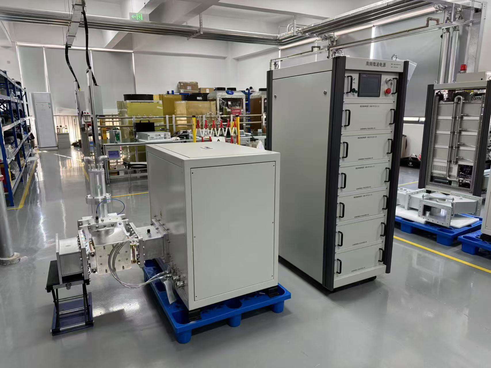
microwave-generator

INDUSTRIAL MICROWAVE POWER FOR OEM AND PROCESS EQUIPMENT

Industrial Microwave Generators

SDACME supplies magnetron-based industrial microwave generators for equipment manufacturers, system integrators and industrial users. The current standard range covers 2450 MHz models at 6, 10 and 15 kW, plus 915 MHz high-power options at 25, 30, 75 and 100 kW. Each configuration is selected from the required power, application load, waveguide interface, control method, cooling conditions and final scope of supply.

2450 MHz Product Family
6 / 10 / 15 kW

For compact and medium-power equipment integration, plasma, MPCVD and selected research systems.

915 MHz High-Power Family
25 / 30 / 75 / 100 kW

For high-power industrial heating, plasma and OEM equipment projects. The 30 kW option is project-configured.

  • Continuous-wave magnetron microwave source architecture
  • Local HMI and communication control on confirmed models
  • External water cooling with model-specific circuits
  • OEM integration and replacement review based on actual interfaces

Provide the application, target power, quantity and destination country for an initial review.
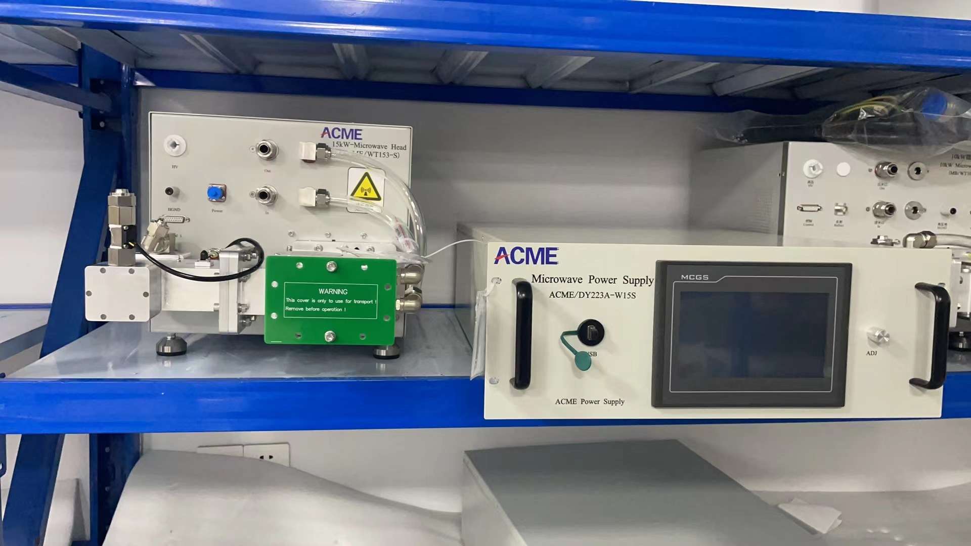
15 kW 2450 MHz microwave generator power supply and microwave head
2450 MHz Family Example 15 kW Microwave Generator
75 kW 915 MHz high-power microwave generator system in a test area
915 MHz High-Power Family Example 75 kW Microwave Generator
PRODUCT RANGE

Select the Right Microwave Generator Family

The SDACME microwave generator range is divided by frequency family and rated power. The current standard line uses continuous-wave magnetron technology and external water cooling. Product cards and the comparison tables below are for initial screening only; exact dimensions, adjustable range, cooling circuits, protection logic and communication details remain model-specific.

COMPACT & MEDIUM POWER

2450 MHz Product Family

2450 MHz

The 2450 MHz family includes 6, 10 and 15 kW industrial microwave generators. These models are typically evaluated for compact or medium-power OEM equipment, plasma and PCVD systems, MPCVD and diamond-growth equipment, laboratory systems and other projects that require a controllable industrial microwave source.
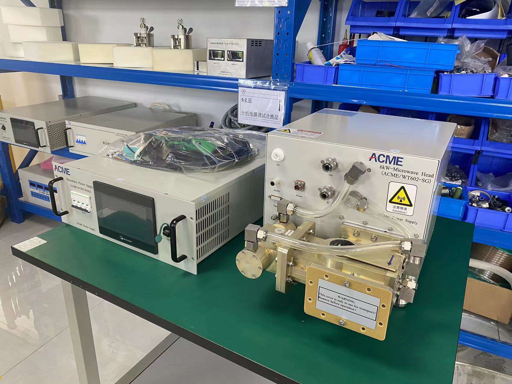
6 kW 2450 MHz microwave generator power supply and microwave head
2450 MHz Magnetron

6 kW Microwave Generator

Entry point for lower-power industrial, laboratory and OEM microwave-source integration.

View 6 kW Model
10 kW 2450 MHz microwave generator power supply and microwave head
2450 MHz Magnetron

10 kW Microwave Generator

A medium-power route for industrial equipment, plasma systems and application-specific microwave integration.

View 10 kW Model
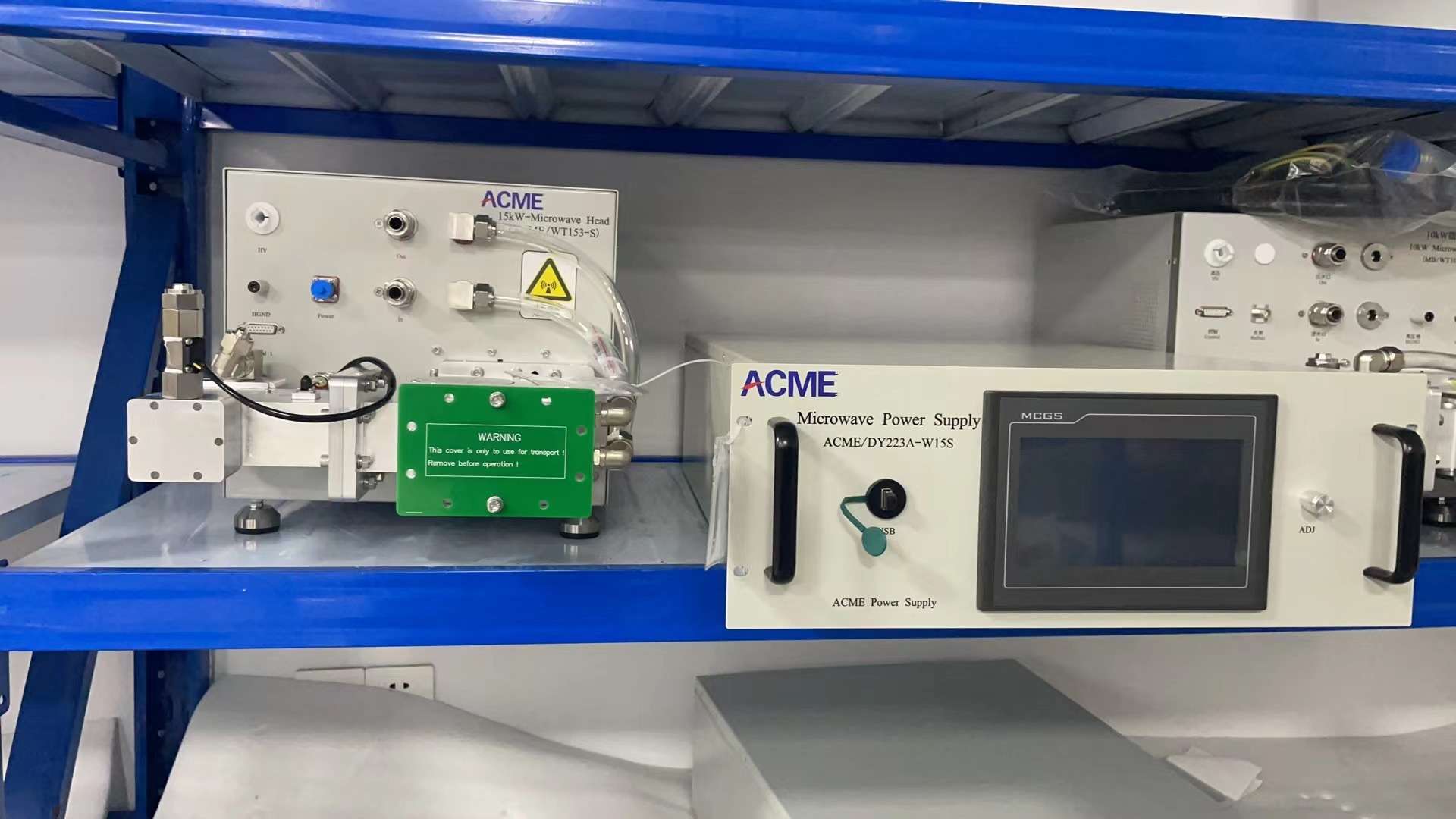
15 kW 2450 MHz industrial microwave generator system
2450 MHz Magnetron

15 kW Microwave Generator

Higher-output 2450 MHz configuration for OEM equipment, plasma, PCVD and MPCVD-related microwave-source requirements.

View 15 kW Model
HIGH-POWER INDUSTRIAL RANGE

915 MHz High-Power Product Family

915 MHz

The 915 MHz family includes 25, 30, 75 and 100 kW options for project-based high-power integration. The 30 kW option is retained as an engineering-confirmed configuration and is routed through the 915 MHz series or technical inquiry process rather than an independent model page. Destination-country spectrum requirements must be checked before a final configuration is confirmed.
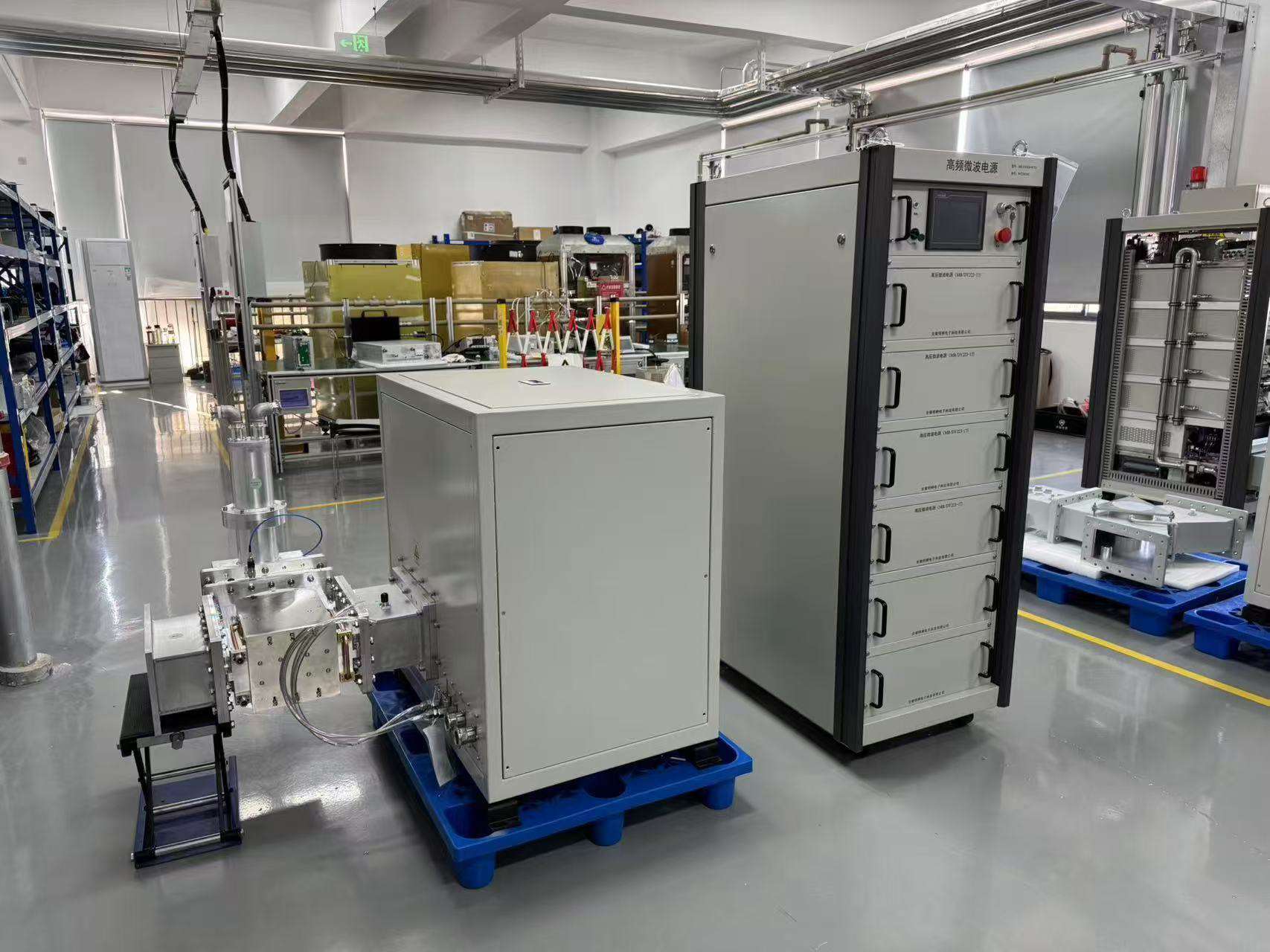
75 kW 915 MHz high-power microwave generator system
915 MHz Family Example 75 kW High-Power Microwave Generator
25 kW

25 kW Microwave Generator

High-power 915 MHz configuration for project-based industrial integration.

View Model
30 kW
Project Configuration

30 kW Microwave Generator

Engineering-confirmed 915 MHz option supplied through project-specific configuration review.

Discuss 30 kW Configuration
75 kW

75 kW Microwave Generator

High-power 915 MHz generator configuration for industrial and equipment-integration projects.

View Model
100 kW

100 kW Microwave Generator

Project-oriented high-power microwave source for system-level integration requirements.

View Model

Rated Power Is Only the First Selection Step

A rated-power match is only the first filter. Final selection must also review the application load, chamber or applicator, reflected-power conditions, waveguide connection, site electrical supply, cooling capacity, control interface and required system components.

Continue to Frequency Selection
FREQUENCY SELECTION

Choose Frequency by the Complete Application, Not Power Alone

Frequency selection is a system decision. A 2450 MHz microwave source and a 915 MHz high-power microwave generator should not be treated as interchangeable products simply because the rated power appears similar. The correct direction depends on the required power level, load or reactor geometry, applicator and waveguide design, available cooling, installation footprint, existing equipment interfaces and the rules that apply in the destination country.

2450 MHz
Compact & Medium Power

2450 MHz Direction

Current Standard Range 6 / 10 / 15 kW

Typically evaluated for compact and medium-power equipment integration where the generator must match the chamber, applicator, waveguide connection and process load.

  • Compact and medium-power OEM integration
  • BJ26 and project-specific connection review
  • External water cooling with model-specific circuits
915 MHz
High-Power Industrial Range

915 MHz Direction

Current Standard Range 25 / 30 / 75 / 100 kW

Typically evaluated for high-power industrial and OEM equipment projects where load behavior, site utilities, protection, cooling capacity and regulatory route require complete review.

  • High-power industrial and OEM integration
  • BJ9-class and project-specific interface review
  • Site power and cooling capacity must be planned
ENGINEERING COMPARISON

What Should Be Compared Before Frequency Selection?

The frequency decision should be reviewed together with the generator, process equipment and installation environment.

Selection Factor
2450 MHz Direction
915 MHz Direction
Current Standard Power Options
6 / 10 / 15 kW
25 / 30 / 75 / 100 kW
Typical Project Scale
Compact and medium-power equipment integration
High-power industrial and OEM equipment integration
Interface Review
BJ26 and project-specific connection details
BJ9-class and project-specific high-power connection details
Load and Applicator
Coupling, chamber geometry and reflected power must be reviewed
High-power load, protection, applicator and site utilities require a complete review
Cooling and Installation
External water cooling; model-specific circuits and clearance
Higher site power and cooling capacity; model-specific circuits and installation planning
Spectrum Note
Confirm intended market and equipment classification
Confirm the destination-country band and regulatory route before final selection
BEFORE WE RECOMMEND A FREQUENCY

Prepare the Main Application Inputs

A useful frequency recommendation starts with the actual equipment and load rather than a requested power number alone.

01
Application & Load

Material, plasma or reactor load and the intended operating purpose.

02
Target Power

Required operating power and whether the project is new equipment or an existing-system replacement.

03
Applicator or Chamber

Chamber geometry, applicator arrangement, cavity information or existing machine drawings.

04
Waveguide Interface

Existing flange, waveguide route, mechanical connection and available installation space.

05
Power & Cooling

Site electrical supply, available cooling water and utility conditions.

06
Destination Country

Final market and equipment route for frequency and regulatory review.

Engineering Note

Neither Frequency Is Universally Better

Neither frequency is universally more efficient or better for every material. Penetration, uniformity, coupling and process results depend on the full microwave system and the customer's application equipment. SDACME reviews the generator interface and supply scope; the final process result remains a function of the complete machine and process conditions.

NEED HELP WITH THE FREQUENCY DECISION?

Send the Application Before Finalizing Power and Frequency

Share the application, target power, chamber or applicator, electrical supply, cooling conditions and destination country for an initial engineering review.

SYSTEM SCOPE

What Is Included in an Industrial Microwave Generator?

The term “microwave generator” is often used for several different supply levels. For technical evaluation and quotation, the power supply, microwave head, waveguide components, control system, cooling utilities and customer process equipment should be defined separately. This prevents an incomplete component quotation from being mistaken for a complete microwave processing system.
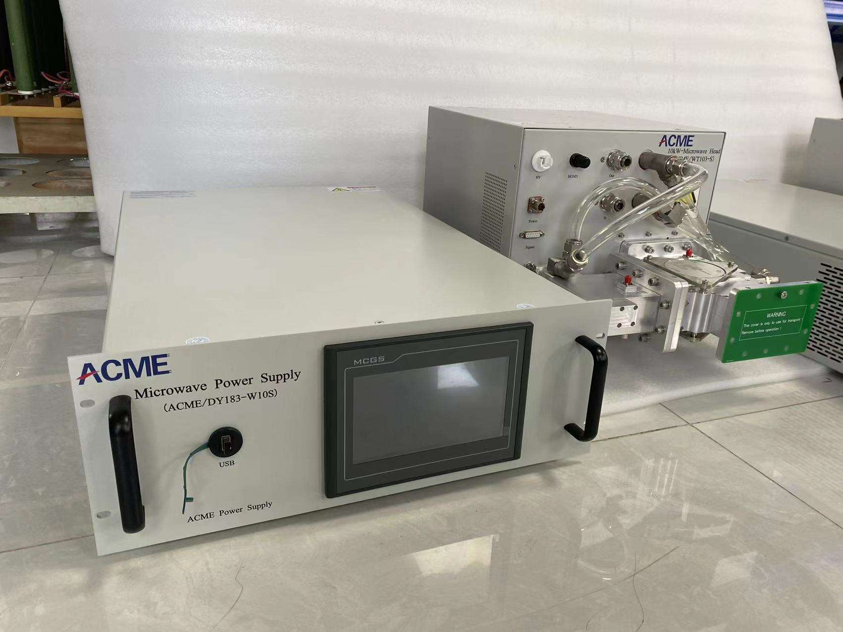
Industrial microwave generator power supply cabinet and microwave head
Representative Hardware Microwave Power Supply + Microwave Head
01

Microwave Power Supply

The electrical power-conversion and control section that supplies the magnetron assembly and manages operating conditions according to the selected model.

02

Microwave Head

The microwave-source assembly containing the magnetron and associated microwave-output structure. Mechanical, cooling and waveguide connections are model-specific.

03

Microwave Generator Package

A project supply package built around the power supply and microwave head, with additional control, protection or microwave-transmission components defined by the application.

04

Complete Processing System

The complete machine may also include the applicator, cavity, chamber, material-handling equipment, process controls, utilities and other equipment outside the microwave-generator supply scope.

FUNCTIONAL BOUNDARY

From Electrical Input to the Customer Load

A typical project can be understood as an energy and interface chain. The exact components between the microwave head and the process load depend on the equipment design.

AC
Site Electrical Supply
PSU
Microwave Power Supply
MW
Microwave Head
RF
Waveguide / Protection Components
LOAD
Applicator / Chamber / Process Load
Core generator hardware Project-defined components Customer/process equipment
SCOPE OF SUPPLY

Define the Supply Boundary Before Quotation

The following items may appear in an industrial microwave project, but they should not be assumed to be standard on every model.

Core Hardware

Generator-Level Equipment

  • Microwave power supply
  • Microwave head / magnetron source assembly
  • Model-specific electrical and cooling interfaces
  • Operating control according to confirmed configuration
Project Configuration

Microwave Transmission & Protection

  • Circulator or isolator
  • Water load
  • Manual or automatic tuner
  • Waveguide sections and transition components
  • Additional monitoring or project controls
Often Customer / Machine Scope

Process Equipment & Site Utilities

  • Microwave applicator or cavity
  • Vacuum or process chamber
  • Material-handling equipment
  • Site cooling-water system
  • Main machine PLC and process control
PROJECT-DEPENDENT COMPONENTS

Additional Components Are Selected from the Actual Load

Reflection behavior, chamber geometry, operating power and the required protection strategy determine whether additional microwave-line components are needed.

C
Circulator / Isolator

Used in selected systems to help manage reflected microwave energy and protect the source path.

W
Water Load

May be used with a protection arrangement to absorb diverted microwave energy.

T
Tuning Components

Matching or tuning elements can be evaluated according to the cavity, applicator and load behavior.

WG
Waveguide & Transitions

Mechanical routing, flange type and installation geometry must match the actual equipment.

FOR AN ACCURATE SCOPE OF SUPPLY

Tell Us What You Already Have and What You Need Supplied

For a new system or replacement project, send the existing equipment information and identify which parts must be included in the quotation.

01 Required frequency and power 02 Existing waveguide or flange 03 Chamber or applicator drawings 04 Control and communication requirements 05 Cooling-water conditions 06 Components already supplied by your machine
Define Your Required Supply Scope
CONTROLS, MONITORING & PROTECTION

Control the Microwave Source and Protect the Equipment

Industrial microwave generators require more than power adjustment. The control architecture must coordinate operating commands, generator status, alarm handling, forward and reflected power, cooling conditions and the interlocks required by the machine. Available interfaces and monitoring functions vary by model and project configuration.
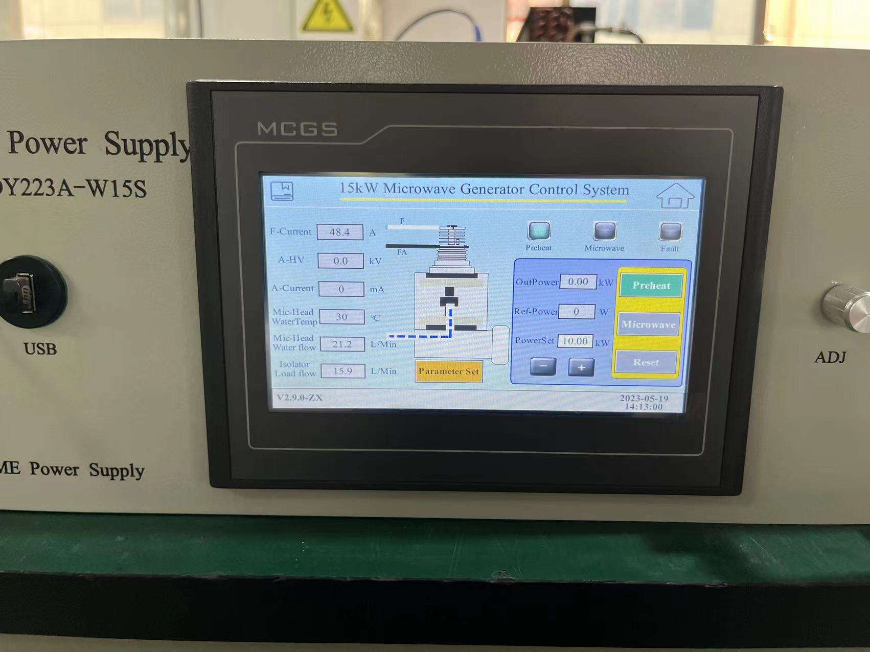
HMI control interface on a 15 kW microwave generator
Control Interface Example 15 kW Microwave Generator HMI
LOCAL OPERATION

HMI-Based Local Control on Confirmed Configurations

Confirmed models can use an HMI for local operation, parameter setting, operating-status display and alarm review. The exact screen layout, adjustable parameters and available functions are defined by the selected generator configuration.

P
Power Setting

Set or adjust microwave output within the operating range confirmed for the selected model.

S
Status Monitoring

Review generator operating state and available equipment feedback on the configured interface.

A
Alarm Information

Display configured fault and protection information for troubleshooting and machine integration.

I/O
External Interface

Communication and external control are selected according to model capability and project requirements.

HIGH-POWER CONTROL EXAMPLE

Control Architecture Scales with the Generator System

Higher-power microwave systems also require coordinated control, protection and utility monitoring. The actual signal list, communication interface and protection logic should be confirmed during technical review rather than assumed from the rated power alone.

  • Generator start / stop and operating-state coordination
  • Power command and model-specific operating feedback
  • Cooling and machine interlock coordination
  • Alarm and shutdown logic based on the confirmed configuration
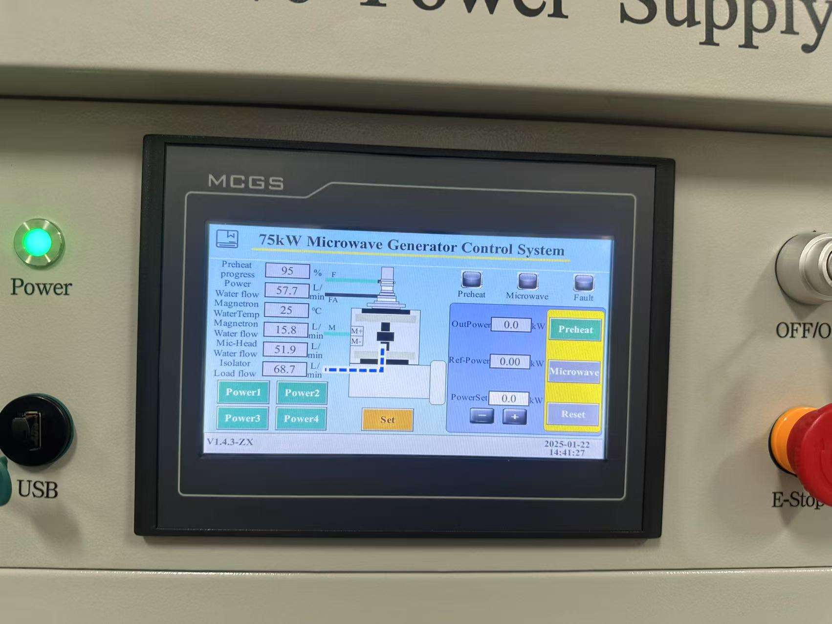
HMI control interface on a 75 kW microwave generator
High-Power Control Example 75 kW Microwave Generator HMI
CONTROL INTERFACES

Interface Options Are Confirmed by Model and Project

Different equipment projects may require local control, communication with a machine PLC, external analog commands or status signals. These functions should be confirmed against the specific generator rather than treated as universal standard features.

Local

HMI / Local Operation

Local operating control and status display can be provided on confirmed models and configurations.

Serial

RS485 Communication

RS485 is supported on confirmed models. Protocol and register details should be checked before PLC integration.

Protocol

Modbus RTU

Available on specified configurations where confirmed by the model documentation and project interface requirements.

Analog

Analog Control Signals

Analog input or output signals may be evaluated when the machine-control architecture requires them.

Discrete

Dry Contact / Digital I/O

Start, stop, status or interlock signals can be reviewed as part of the project signal definition.

OEM

Machine PLC Integration

OEM projects can define the required command, feedback, alarm and safety-handshake signals before final configuration.

PROTECTION LOGIC

Protection Must Cover the Source, Utilities and Machine State

Protection functions depend on model and system design, but industrial microwave equipment normally requires coordinated monitoring of source conditions, reflected energy, cooling, electrical conditions and external machine interlocks.

RF
Reflected Power

Reflected microwave energy can be monitored and incorporated into the protection strategy on confirmed configurations.

H₂O
Cooling Conditions

Cooling-water status and related interlocks are coordinated with the specific generator and cooling circuit design.

HV
Electrical Faults

Electrical protection is integrated with the power-supply and generator-control architecture.

INT
External Interlocks

Door, chamber, process or machine-permission signals can be included in the system interlock review.

TMP
Temperature Conditions

Applicable thermal conditions and alarm points are determined by the selected equipment and project design.

E
Emergency Shutdown

Emergency-stop and machine shutdown logic should be integrated with the complete equipment safety architecture.

OEM INTEGRATION

Define the Signal List Before Equipment Integration

For an OEM machine, replacement project or PLC-controlled system, the interface should be reviewed before production so that the generator and machine control logic are compatible.

Machine / PLC Command Signals Start / stop · power command · enable · reset
Microwave Generator Control & Monitoring Generator logic · protection · operating feedback
Machine / PLC Feedback Signals Ready · running · alarm · fault · status
Configuration Note

Do Not Assume Every Interface Is Standard on Every Model

HMI, RS485, Modbus, analog I/O, dry-contact signals, remote control and data-related functions are confirmed according to the actual model and project configuration. Send your machine-control requirements before the final generator configuration is selected.

PLANNING PLC OR OEM INTEGRATION?

Send Your Required Control Interface and Signal List

Include the generator model or target power, control method, required communication protocol, external interlocks and available machine PLC information.

Review Control Requirements
COOLING & INSTALLATION

Plan Cooling and Installation Together with Generator Selection

Industrial microwave generators use external cooling and require model-specific electrical, mechanical and microwave interfaces. Cooling capacity, connection points, cabinet position, waveguide routing and machine interlocks should therefore be reviewed before the generator is installed in new or existing equipment.
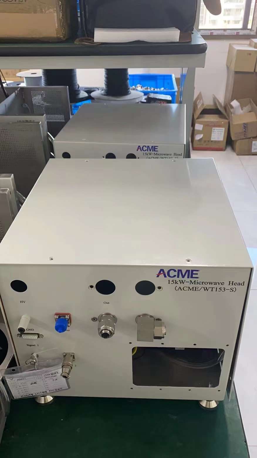
15 kW microwave head showing cooling and connection interfaces
Interface Example 15 kW Microwave Head Connections
MICROWAVE HEAD INTERFACES

Cooling, Waveguide and Mechanical Connections Must Match the Machine

The microwave head is not an isolated component. Its cooling connections, microwave-output interface, mounting position and service access must fit the surrounding machine. Existing equipment projects should provide interface photos or drawings before a replacement or retrofit configuration is finalized.

01
Cooling Connections

Connection arrangement and cooling circuits are confirmed for the selected model.

02
Waveguide Interface

Flange type, connection direction and waveguide route must match the equipment layout.

03
Mechanical Position

Mounting space and orientation should allow installation, inspection and maintenance.

04
Cable Routing

Power, control and interlock connections should be planned together with cabinet and microwave-head positions.

COOLING SYSTEM

Cooling Requirements Are Model-Specific

Cooling must be treated as part of the generator installation. The final water circuit, operating conditions and connection arrangement are confirmed against the selected microwave source and project environment.

SITE Cooling-Water Supply

Customer or machine cooling-water source.

GENERATOR Model-Specific Cooling Circuits

Cooling arrangement depends on the confirmed generator design.

RETURN Cooling-Water Return

Return route is coordinated with the machine utility system.

01 Water Temperature

Confirm available inlet conditions for the selected model.

02 Flow Capacity

Confirm that the external cooling system can support the required circuit.

03 Water Pressure

Match the site supply with the model-specific cooling requirement.

04 Water Quality

Review water condition and cooling-system compatibility before operation.

HIGH-POWER COOLING EXAMPLE

High-Power Systems Require Utility Planning Before Installation

High-power microwave generators involve larger electrical and thermal loads, so cooling, site power, piping, installation space and service access should be evaluated as a complete package. The photograph shows an actual 75 kW microwave-head cooling arrangement and should be treated as a model example rather than a universal configuration for every 915 MHz system.

Confirm site cooling capacity before final equipment selection.

Reserve access for piping, electrical connections and maintenance.

Review generator cabinet and microwave-head placement together.

Coordinate cooling and protection interlocks with the machine control.
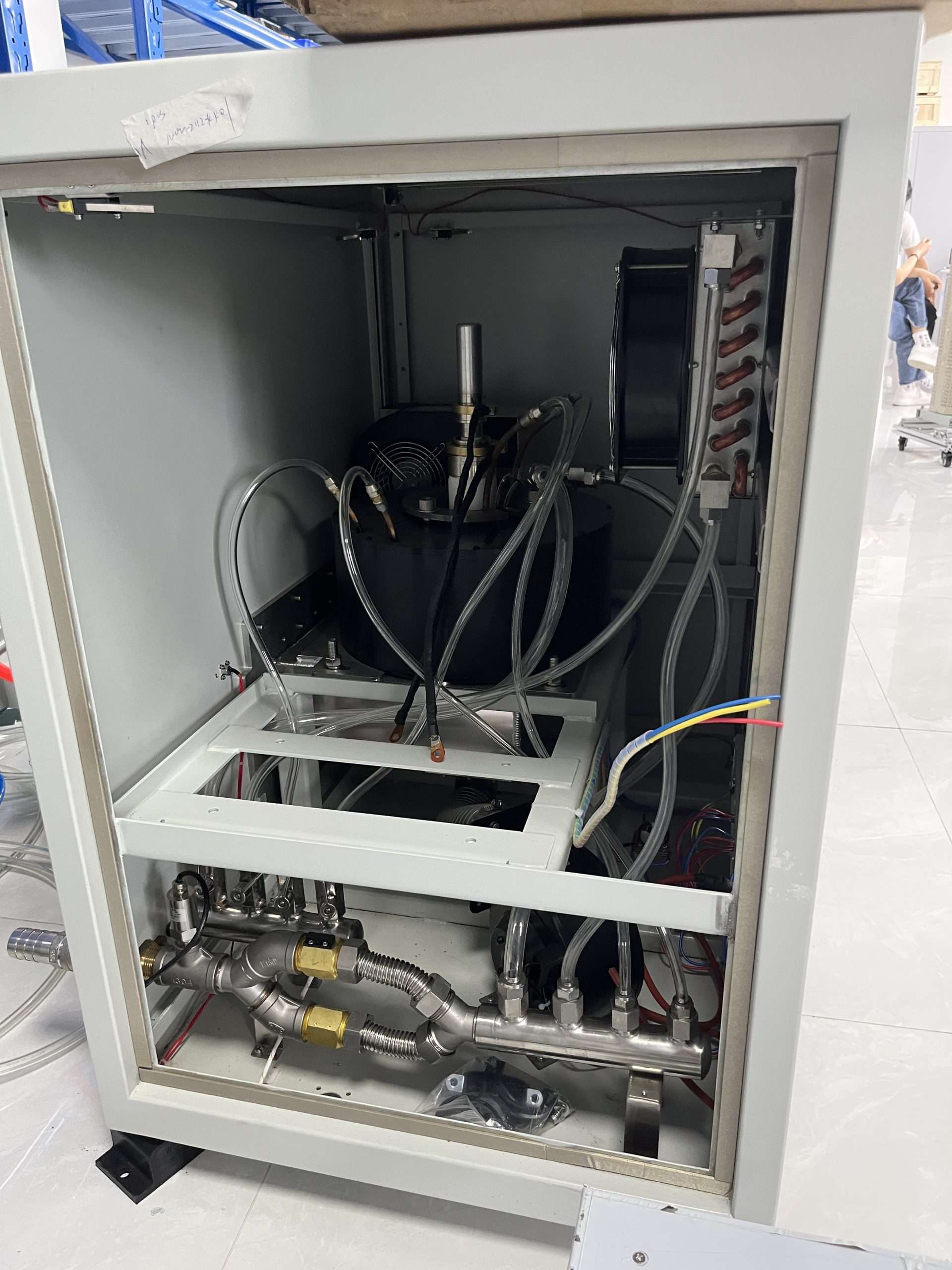
Internal piping and cooling structure of a 75 kW microwave head
75 kW Hardware Example Internal Cooling and Piping Arrangement
INSTALLATION CHECKLIST

Confirm the Site Conditions Before Production or Retrofit

A short installation review before manufacturing reduces the risk of mismatched electrical, cooling, mechanical or waveguide interfaces during commissioning.

AC

Electrical Supply

Confirm site voltage, frequency, available capacity and electrical connection requirements.

H₂O

Cooling Utilities

Provide available cooling-water conditions so the model-specific circuit can be checked.

WG

Waveguide Route

Confirm flange type, waveguide orientation, distance and required transition components.

DIM

Installation Space

Reserve enough space for the cabinet, microwave head, connections and service access.

I/O

Control & Interlocks

Define start, stop, status, alarm and safety-handshake requirements with the machine control.

ENV

Installation Environment

Provide relevant site and operating conditions that may affect equipment layout or utility planning.

NEW EQUIPMENT

New Machine Integration

When the generator is integrated into new equipment, the cabinet, microwave head, waveguide route, cooling connections and control architecture can be planned together from the beginning.

Machine layout Applicator design Available utilities Control architecture
EXISTING EQUIPMENT

Replacement or Retrofit

Existing systems require a compatibility review because the original electrical, mechanical, waveguide, cooling and control interfaces may differ from a new generator configuration.

Existing nameplate Interface photos Waveguide dimensions Current cooling circuit
Installation Note

Do Not Size the Cooling System from Rated Power Alone

Required cooling conditions should be taken from the confirmed generator configuration and technical documentation. Rated microwave output alone is not enough to define water flow, pressure, piping or the final site cooling arrangement.

PLANNING A NEW INSTALLATION OR REPLACEMENT?

Send the Site Utilities and Interface Information

Provide the required power and frequency, site electrical supply, cooling-water conditions, available space, waveguide interface and photos or drawings of the existing equipment.

Review Installation Requirements
APPLICATIONS

Industrial Microwave Generators for Process and OEM Equipment

SDACME microwave generators can be evaluated as microwave-source modules for industrial heating, plasma, deposition, materials research and OEM equipment. The correct generator is selected from the process load, required power, frequency, applicator or chamber, reflected-power conditions, cooling utilities and control requirements rather than from the application name alone.

THERMAL PROCESS

Industrial Heating & Drying

Microwave generators can be evaluated for process equipment that uses microwave energy for heating, drying or related thermal treatment. Final performance depends on the material, moisture content, load geometry, applicator design and process conditions.

Review before selection
  • Material and batch or continuous load
  • Target throughput and process objective
  • Applicator or cavity configuration
  • Required microwave power range
Discuss Heating Application
PLASMA PROCESS

Plasma & PCVD Equipment

Microwave sources can be integrated into plasma and PCVD equipment where the generator must match the resonant structure, chamber, waveguide path, protection arrangement and machine control architecture.

Review before selection
  • Plasma chamber or resonator design
  • Frequency and target operating power
  • Waveguide and coupling interface
  • Reflected-power protection strategy
Discuss Plasma Integration
ADVANCED MATERIALS

Semiconductor & Materials Equipment

Microwave generators can be considered for advanced-material and semiconductor-related equipment where a controlled microwave source is required. Suitability depends on the specific reactor, plasma architecture and process-equipment design.

Review before selection
  • Equipment architecture and process route
  • Reactor or chamber interface
  • Required microwave power and control
  • Integration and utility requirements
Discuss Materials Equipment
RESEARCH EQUIPMENT

Laboratory & R&D Systems

Research systems often require flexible microwave-source integration with custom chambers, experimental applicators, measurement equipment or externally controlled test platforms.

Review before selection
  • Experimental setup and load
  • Required power-adjustment range
  • Measurement and control interface
  • Mechanical and waveguide configuration
Discuss R&D Configuration
MACHINE INTEGRATION

OEM Industrial Equipment

Equipment manufacturers can integrate a microwave generator into a larger machine when the electrical, mechanical, microwave, cooling and control interfaces are defined during the equipment design stage.

Review before selection
  • Machine layout and installation space
  • Electrical and cooling utilities
  • PLC and machine interlocks
  • Supply scope and interface drawings
Discuss OEM Integration
APPLICATION ENGINEERING

The Generator Is One Part of the Microwave Process

The same generator rating can behave differently when the load, cavity, applicator, waveguide, matching conditions or operating process changes. Application review therefore looks beyond the generator nameplate.

01 Microwave Generator

Frequency, power, control and protection configuration.

02 Microwave Delivery

Waveguide, transitions, protection and matching components.

03 Applicator / Reactor

Chamber geometry, resonator, cavity or process applicator.

04 Process Load

Material, plasma, gas environment or other application load.

SYSTEM Final Process Performance

Determined by the complete machine and operating conditions.

INITIAL APPLICATION SCREENING

What Information Changes the Generator Recommendation?

LOAD Material or Process Load

The dielectric, plasma or reactor load affects coupling and reflected-power behavior.

POWER Required Operating Power

Target power helps narrow the 2450 MHz or 915 MHz product family but does not determine the full configuration alone.

CHAMBER Chamber or Applicator

Geometry and coupling architecture affect the generator and microwave-delivery design.

CONTROL Machine Control

OEM and process equipment may require specific commands, interlocks and communication interfaces.

UTILITY Electrical & Cooling Utilities

Available site power and cooling conditions must support the selected generator.

MARKET Destination Country

Frequency selection and the final equipment route should be checked for the intended market.

Application Note

Application Suitability Does Not Mean a Guaranteed Process Result

Microwave output power is only one variable in an industrial process. Heating rate, temperature uniformity, plasma behavior, deposition performance, material quality and production output depend on the complete equipment and process conditions. Generator selection should therefore be reviewed together with the customer's applicator, reactor or machine design.

START AN APPLICATION REVIEW

Send Six Inputs for an Initial Generator Recommendation

01 Application What process or equipment will use the microwave source?
02 Load Material, plasma, reactor or other operating load.
03 Target Power Required power or existing generator rating.
04 Equipment Interface Chamber, applicator, waveguide, drawings or existing photos.
05 Site Conditions Electrical supply, cooling water and installation environment.
06 Destination Country and quantity for project evaluation.
HAVE A SPECIFIC MICROWAVE APPLICATION?

Start with the Process and Equipment Requirements

Send the application, target power, load information, chamber or applicator details, available utilities and destination country. We can then review the appropriate microwave-generator direction and required supply scope.

OEM INTEGRATION & REPLACEMENT

Integrate a Microwave Generator into New or Existing Equipment

SDACME supports microwave-generator projects for equipment manufacturers, system integrators and users replacing an existing microwave source. The correct configuration is determined from the electrical, microwave, mechanical, cooling and control interfaces of the complete machine. For replacement projects, compatibility should be reviewed before a substitute generator is selected.
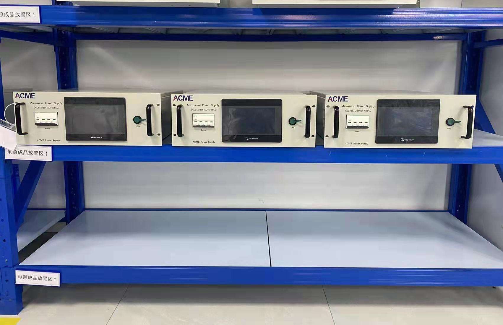
Multiple industrial microwave power supply units arranged on a production rack
Equipment Supply Example Multiple Industrial Microwave Power Supply Units
OEM SUPPLY

Generator Configuration Should Follow the Machine Architecture

OEM integration starts from the machine rather than from a generator model alone. Power rating is only one part of the selection. The generator must also fit the intended waveguide connection, cooling system, installation space, control method and machine safety logic.

01
Model Selection

Select frequency and rated power from the process and machine requirements.

02
Interface Definition

Confirm electrical, waveguide, cooling, mounting and control connections.

03
Supply Scope

Define whether the project requires only the source hardware or additional microwave-line components.

04
Machine Integration

Coordinate generator commands, feedback and interlocks with the complete equipment.

NEW EQUIPMENT

OEM Machine Integration

For new machines, the microwave generator can be selected while the equipment layout and control architecture are still being defined. This allows the electrical cabinet, microwave head, waveguide route, cooling connections and signal interface to be coordinated before production.

  • Equipment layout or concept drawing
  • Required microwave frequency and power
  • Chamber or applicator interface
  • Available electrical and cooling utilities
  • PLC and control-interface requirements
Discuss OEM Integration
EXISTING EQUIPMENT

Microwave Generator Replacement

For an existing machine, the replacement generator must be compared with the original source and the surrounding equipment. Differences in waveguide interface, cooling, electrical supply, dimensions or control logic may require engineering adaptation.

  • Original generator nameplate
  • Existing power and frequency
  • Power-supply and microwave-head photos
  • Waveguide and mechanical dimensions
  • Electrical, cooling and control information
Check Replacement Compatibility
REPLACEMENT COMPATIBILITY

Six Interfaces Should Be Checked Before Replacement

Matching only the rated power is not enough. A replacement review should compare the existing equipment with the proposed microwave generator across the main system interfaces.

01

Frequency & Power

Confirm the existing operating frequency, rated power and required adjustment range.

02

Electrical Input

Compare site voltage, frequency, capacity, wiring and electrical-connection requirements.

03

Waveguide Interface

Check flange type, waveguide size, direction, location and transition requirements.

04

Mechanical Installation

Compare cabinet dimensions, microwave-head position, mounting arrangement and available service space.

05

Cooling System

Confirm cooling connections and whether the existing utility system can support the proposed configuration.

06

Control & Interlocks

Compare start, stop, power command, status, alarm, communication and machine-safety signals.

COMPATIBILITY MATRIX

What Can Be Matched and What May Require Adaptation?

Interface
What We Review
Possible Outcome
Microwave Output
Frequency, rated power and operating requirement
Equivalent direction or revised configuration
Waveguide
Flange, size, orientation and existing route
Direct connection or transition component
Mechanical
Cabinet and microwave-head dimensions
Existing position or mounting adaptation
Cooling
Existing piping and cooling utility
Reuse, modification or revised cooling route
Control
Existing PLC commands, feedback and communication
Direct interface or signal adaptation
Protection
Machine interlocks and microwave protection arrangement
Retained logic or revised integration
REPLACEMENT REVIEW PROCESS

From Existing Generator Information to a Replacement Proposal

STEP 01 Identify Existing Equipment

Send the nameplate, manufacturer/model information and clear photos of the original microwave equipment.

STEP 02 Compare Interfaces

Review frequency, power, electrical input, waveguide, cooling, dimensions and machine-control signals.

STEP 03 Define Adaptation

Identify any required transition, mounting, piping or control-interface changes.

STEP 04 Confirm Supply Scope

Finalize the generator package and the components included in the project quotation.

SPEED UP THE REVIEW

What Should You Send for a Replacement Project?

Photos and interface information are usually more useful than a model name alone, especially when the original generator is no longer available or the machine has been modified.

01 Original generator nameplate
02 Power-supply cabinet photos
03 Microwave-head photos
04 Waveguide and flange dimensions
05 Electrical-input information
06 Cooling-water connections
07 PLC / control wiring information
08 Available installation dimensions
Compatibility Note

Replacement Does Not Automatically Mean Drop-In Replacement

Even when frequency and rated power are similar, different microwave generators may use different electrical inputs, dimensions, waveguide interfaces, cooling circuits, control signals or protection logic. Compatibility should therefore be confirmed from the actual existing equipment before installation.

REPLACING AN EXISTING MICROWAVE GENERATOR?

Send the Nameplate, Photos and Interface Information

We can review the existing frequency, power, electrical supply, waveguide connection, cooling system, mechanical dimensions and control interface before proposing a replacement direction.

FUNCTIONAL TESTING & DOCUMENTS

Verify the Microwave Generator Before Shipment

Functional verification helps confirm that the selected microwave generator operates according to the agreed configuration before it is integrated into the customer's equipment. Test items can cover generator operation, HMI functions, microwave output, spectrum, alarms, protection logic and required interfaces. The final test scope depends on the model and project requirements.
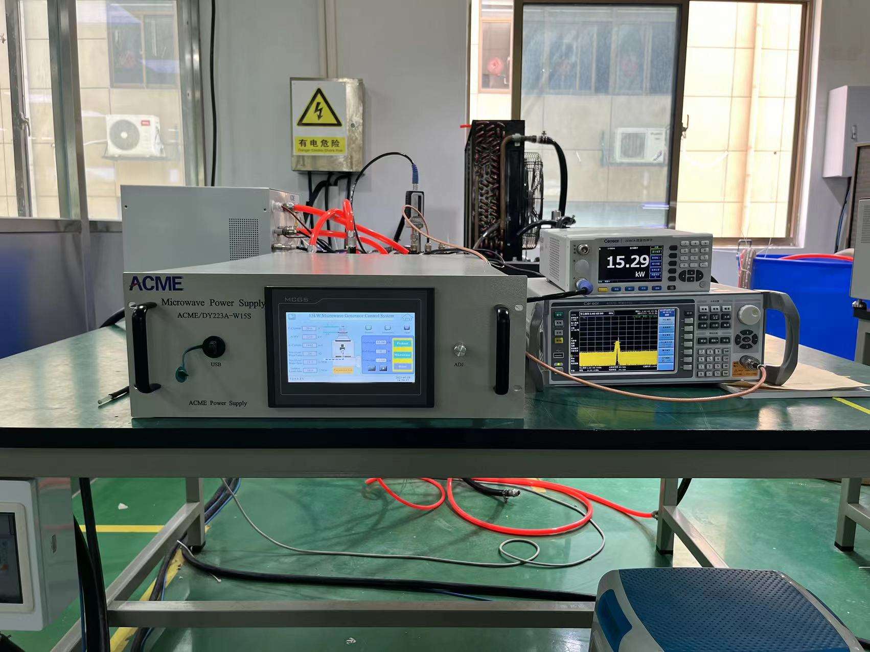
15 kW microwave generator connected to HMI and measurement instruments during functional testing
Functional Test Example 15 kW Microwave Generator with HMI and Measurement Instruments
PRE-SHIPMENT VERIFICATION

Test the Generator as an Operating Equipment Package

A useful test is not limited to checking whether the cabinet can power on. The generator should be operated with the relevant control and measurement equipment so that operating status, microwave output and configured protection functions can be reviewed before shipment.

01
Start / Stop Operation

Confirm normal operating sequence and basic generator response.

02
HMI Functions

Review the configured operating screens, settings and status information.

03
Microwave Output

Verify output behavior using the applicable test arrangement and measurement equipment.

04
Alarm & Protection

Check the protection and alarm functions included in the confirmed configuration.

TEST EVIDENCE

Examples of Control, Power and Spectrum Verification

The following images show actual test scenes from 15 kW and 6 kW microwave-generator configurations. Instrument readings shown in individual photographs relate to those specific test conditions.
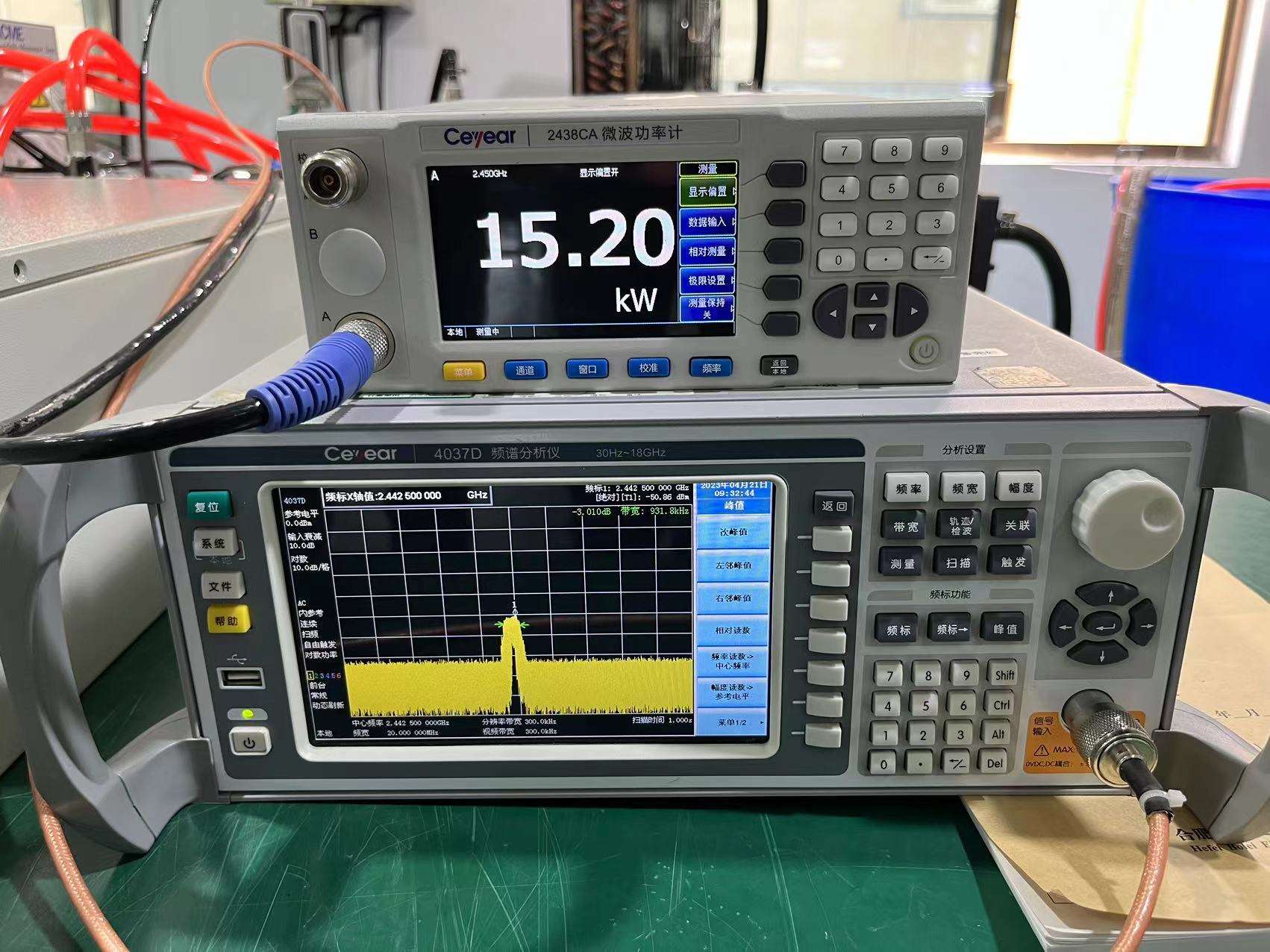
Power meter and spectrum analyzer used during a 15 kW microwave generator test
15 kW TEST EXAMPLE Power & Spectrum Measurement

Measurement instruments are used to review microwave output under the applicable test setup.
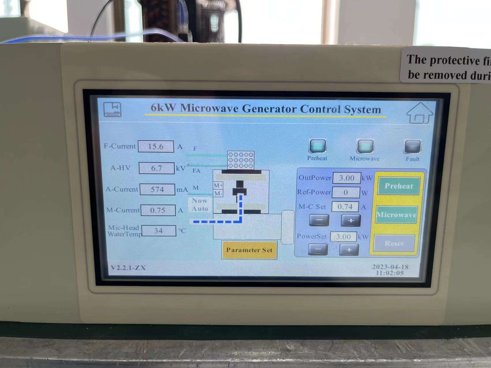
HMI control interface displayed during a 6 kW microwave generator test
6 kW TEST EXAMPLE HMI Operating Interface

The control interface provides an operating view of the confirmed generator configuration.
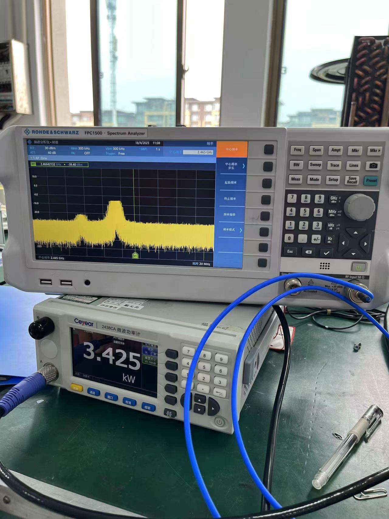
Spectrum and power measurement instruments used during a 6 kW microwave generator test
6 kW TEST EXAMPLE Spectrum & Power Verification

Test instruments can be used to review microwave-source behavior before equipment delivery.

FUNCTIONAL TEST ITEMS

What Can Be Included in a Generator Test?

Test content should follow the confirmed equipment configuration. Not every item below applies to every model or project.

RUN

Operating Sequence

Start, stop, enable, reset and other configured operating functions.

PWR

Microwave Output

Review output under the defined test condition using appropriate measurement equipment.

RF

Spectrum

Frequency-domain behavior can be reviewed where applicable to the confirmed test scope.

HMI

HMI & Control

Check configured operating screens, settings and equipment feedback.

I/O

External Interfaces

Verify communication or control interfaces included in the agreed project configuration.

ALM

Alarm Functions

Review applicable alarm indications and configured fault responses.

INT

Interlocks

Confirm relevant cooling, machine or safety-permission interlocks where included.

VIS

Visual Inspection

Check equipment condition, connections, labels and agreed external configuration before packing.

TEST WORKFLOW

From Configuration Confirmation to Test Record

STEP 01 Confirm Configuration

Lock the generator model, interfaces and project-specific functions that require verification.

STEP 02 Prepare Test Setup

Connect the generator with the applicable load, controls and measurement equipment.

STEP 03 Functional Verification

Run the agreed operating, control, measurement and protection checks.

STEP 04 Record & Release

Complete the agreed test record and prepare the equipment for the next delivery stage.

TECHNICAL DOCUMENTS

Define Required Documents with the Project

Documentation requirements vary between standalone generator purchases, OEM integration and replacement projects. Required documents should therefore be confirmed as part of the supply scope.

DOC
Product Specification

Model-specific technical data and main equipment information.

MAN
Operation Documentation

Available operating and maintenance information for the confirmed equipment.

I/O
Interface Information

Electrical, control, communication or connection information required for integration.

DWG
Drawings

Applicable equipment or interface drawings can be defined according to project requirements.

TEST
Test Records

Agreed functional-test information can be included according to the project scope.

FAT
Project Test Protocol

If a formal FAT or customer-defined test procedure is required, the test scope should be agreed before execution.

Test Scope Note

Generator Testing Is Different from Final Process Validation

Generator-level functional testing can verify the microwave source, controls and configured interfaces under the agreed test conditions. Final heating, plasma, deposition or material-process performance depends on the customer's complete chamber, applicator, machine and operating process.

NEED SPECIFIC TEST OR DOCUMENT REQUIREMENTS?

Define the Acceptance Scope Before the Generator Is Prepared

Send the target model, application, required interfaces and any customer-specific test or documentation requirements so they can be reviewed with the project scope.

SUPPLIER EVALUATION & PROJECT WORKFLOW

Evaluate the Generator, Interfaces and Project Process Together

Selecting an industrial microwave generator supplier involves more than comparing rated power and price. A practical evaluation should also review the frequency family, system scope, control interfaces, cooling requirements, replacement compatibility, functional testing, technical documents and the information required before production and shipment.
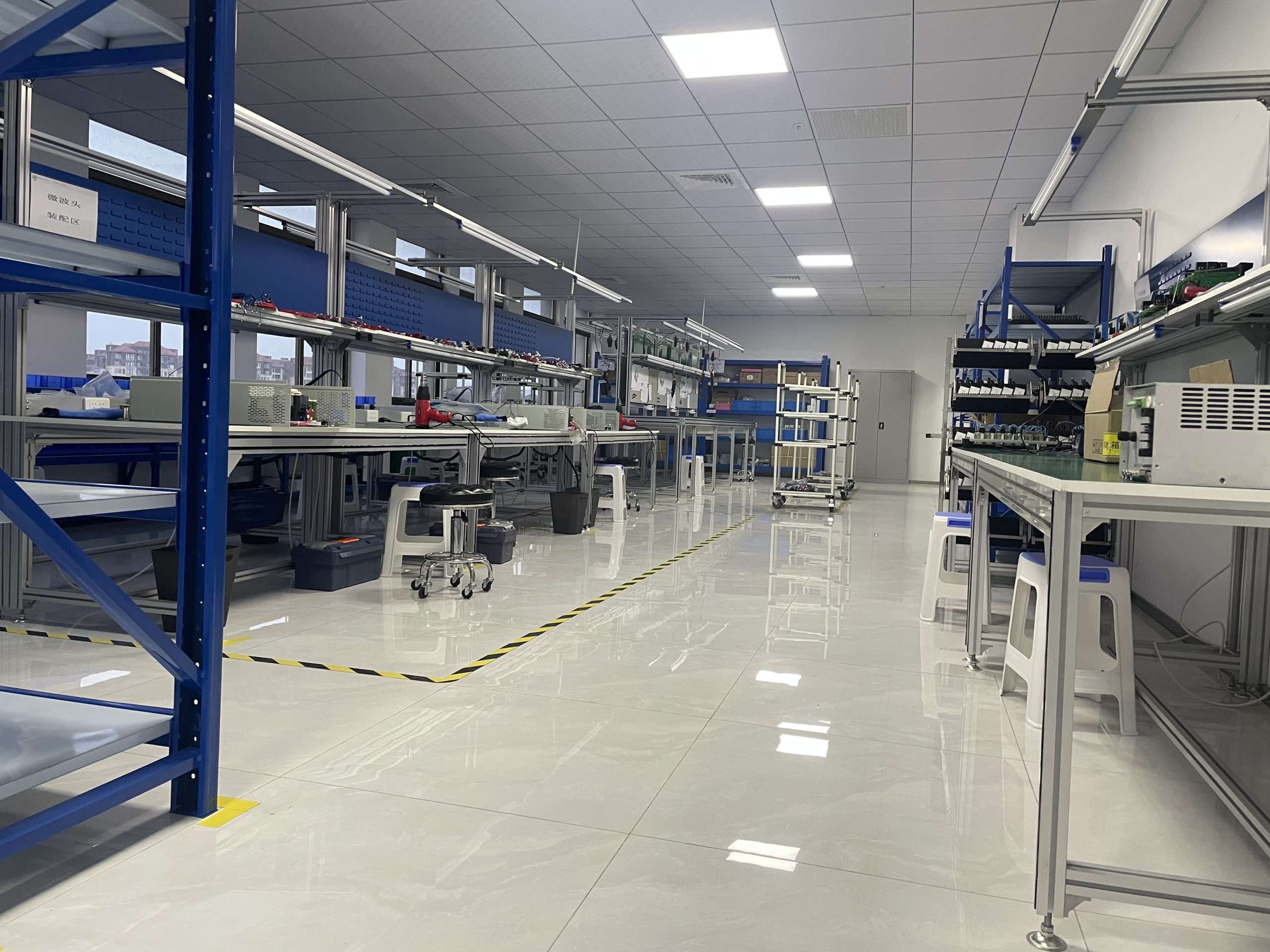
Production and testing area used for microwave generator assembly and verification
Production & Test Environment Microwave Generator Assembly and Verification Area
SUPPLIER EVALUATION

Look Beyond the Product Nameplate

For OEM, replacement and project-based microwave equipment, supplier evaluation should include the ability to review the technical interfaces and prepare the generator according to the agreed configuration. The objective is to reduce integration problems before the equipment reaches the installation site.

01
Product Range

Confirm that the required power and frequency fall within the available generator families.

02
Engineering Review

Review the electrical, waveguide, cooling, mechanical and control requirements before final selection.

03
Functional Verification

Define the operating and test items required for the confirmed configuration.

04
Technical Documentation

Confirm the specification, interface information, drawings and test documents required for the project.

PROJECT WORKFLOW

From Application Requirements to Delivery Preparation

A clear project sequence helps separate the initial product selection from the final engineering configuration.

01
REQUIREMENTS

Application Review

Identify the application, target microwave power, frequency, quantity and destination market.

02
INTERFACES

Technical Definition

Review electrical input, waveguide connection, cooling, dimensions, controls and required protection.

03
SCOPE

Configuration & Quotation

Confirm the generator model and define which power-supply, microwave-head and project components are included.

04
PREPARATION

Equipment Preparation

Prepare the equipment according to the confirmed model, interfaces and project requirements.

05
VERIFICATION

Functional Testing

Perform the agreed generator-level operating, control, measurement and protection checks.

06
DELIVERY

Packing & Documentation

Prepare the confirmed technical documents and equipment for the agreed shipping stage.

BEFORE QUOTATION

Information That Makes a Technical Proposal More Accurate

The more complete the initial information is, the easier it is to distinguish a simple generator purchase from an OEM, retrofit or system-level project.

01
Application

Heating, plasma, MPCVD, materials equipment, R&D or another microwave process.

02
Required Power

Target microwave output or existing generator rating.

03
Frequency

Existing or preferred 2450 MHz / 915 MHz direction where known.

04
Chamber / Applicator

Drawings, dimensions or equipment information that affects microwave coupling.

05
Waveguide Interface

Existing flange, waveguide size, orientation and connection route where applicable.

06
Site Utilities

Electrical supply and available cooling-water conditions.

07
Control Requirements

Local HMI, PLC integration, communication, interlocks or other required signals.

08
Project Type

New equipment, OEM integration or replacement of an existing microwave source.

09
Destination & Quantity

Destination country and required quantity for commercial and frequency-route review.

DELIVERY PREPARATION

Protect High-Power Components for the Shipping Stage

After the agreed functional verification is completed, equipment can move into packing and delivery preparation. Packaging should protect the generator components and connection areas during handling and transportation. Final packing depends on the equipment configuration and shipment requirements.

Confirm equipment configuration before packing.

Protect external interfaces and vulnerable connection areas.

Prepare the agreed project documents with the delivery stage.

Coordinate packing with equipment size and shipping method.
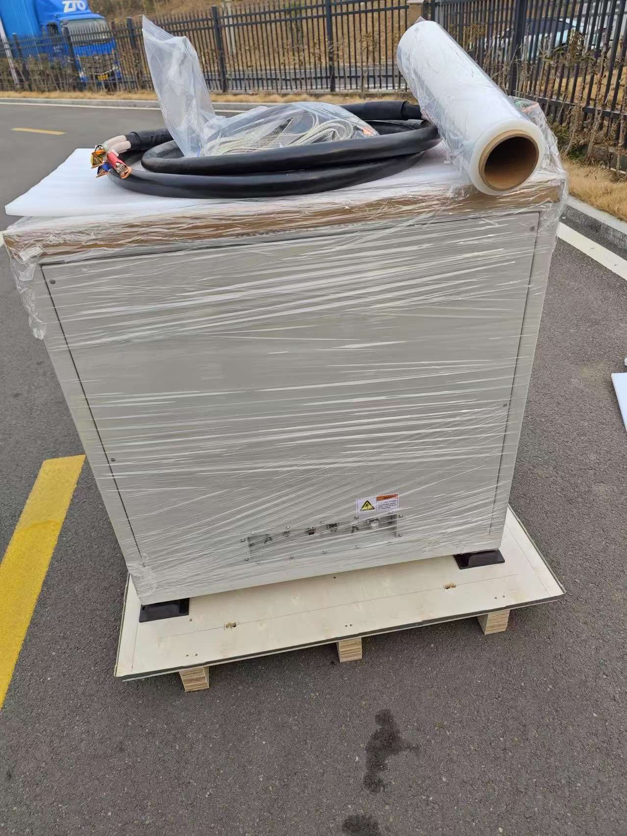
Packaged high-power microwave generator component prepared for shipment
High-Power Equipment Example 75 kW Microwave Generator Component Packaging
PROCUREMENT CHECKLIST

Questions to Ask When Comparing Microwave Generator Suppliers

Evaluation Area
What to Confirm
Why It Matters
Frequency & Power
Available 2450 MHz / 915 MHz models and actual project route
Prevents selecting a generator outside the suitable product family
Interface Review
Electrical, mechanical, waveguide, cooling and control interfaces
Reduces equipment-integration and replacement risk
Supply Scope
Power supply, microwave head and project-dependent components
Prevents component quotations from being mistaken for complete systems
Testing
Functional-test items and any customer-defined acceptance requirements
Clarifies what will actually be verified before shipment
Documents
Specifications, drawings, interface information and agreed records
Supports installation, integration and equipment maintenance
Replacement Support
Existing-equipment compatibility review before final selection
Avoids assuming that similar rated power means direct interchangeability
Procurement Note

Compare the Confirmed Configuration, Not Only the Quoted kW

Two quotations with the same frequency and rated microwave power may still differ in generator architecture, interfaces, controls, protection, cooling requirements, included components, testing and documentation. These items should be compared before the final supplier decision.

READY FOR TECHNICAL REVIEW?

Start with the Application and Interface Requirements

Send your application, target power, frequency, chamber or applicator information, waveguide interface, electrical supply, cooling conditions, control requirements, quantity and destination country for an initial project review.

FREQUENTLY ASKED QUESTIONS

Industrial Microwave Generator FAQs

The following questions cover the main technical points that equipment manufacturers, system integrators and industrial users typically need to clarify before selecting or replacing a microwave generator.

01 What industrial microwave generator power range does SDACME supply?

The current standard range includes 2450 MHz microwave generators at 6, 10 and 15 kW, plus 915 MHz high-power options at 25, 30, 75 and 100 kW. The 30 kW option is handled as a project configuration within the 915 MHz family rather than as a separate standalone model page.

02 How do I choose between 2450 MHz and 915 MHz?

Frequency should be selected from the complete application rather than rated power alone. The review should consider the required microwave power, process load, chamber or applicator geometry, waveguide interface, cooling capacity, installation space and the destination market. Neither frequency is universally better for every industrial process.

Review Frequency Selection
03 What is the difference between a microwave power supply, microwave head and microwave generator?

The microwave power supply provides and controls the electrical power required by the magnetron assembly. The microwave head is the microwave-source assembly that generates microwave energy. A microwave generator package can combine these core components with project-defined control, protection or microwave-transmission components.

A complete industrial microwave processing system may also require an applicator, chamber, cavity, waveguide system, process controls, utilities and material-handling equipment.

Review System Scope
04 Can the microwave generator be integrated into OEM equipment?

Yes. OEM integration can be reviewed when the machine manufacturer provides the required frequency and power, electrical supply, waveguide connection, installation dimensions, cooling conditions, control method and machine interlocks.

Defining these interfaces before equipment production helps reduce mechanical, electrical and control-integration problems later in the project.

Review OEM Integration
05 Can SDACME replace an existing industrial microwave generator?

Replacement projects can be evaluated, but compatibility should be checked before a substitute generator is selected. Matching rated power alone is not sufficient.

The existing frequency, electrical input, waveguide interface, cabinet and microwave-head dimensions, cooling connections, control signals and protection logic should be compared with the proposed configuration.

Review Replacement Compatibility
06 Is a replacement microwave generator a direct drop-in replacement?

Not automatically. Two microwave generators with similar frequency and power may still use different electrical connections, waveguide flanges, cooling circuits, dimensions, control signals or protection logic.

A direct replacement should only be confirmed after the actual interfaces of the existing equipment have been reviewed.

07 What control interfaces are available for microwave generators?

Confirmed configurations can include local HMI operation and external machine-control interfaces. Depending on the selected model and project, interfaces may include RS485, Modbus RTU, analog signals, digital I/O or dry-contact signals.

The required protocol, commands, feedback signals and machine interlocks should be confirmed before final configuration.

Review Controls & Protection
08 Do industrial microwave generators require water cooling?

The current generator configurations use external water cooling with model-specific cooling circuits. The required water temperature, flow, pressure, connection arrangement and cooling capacity should be taken from the confirmed model documentation.

Rated microwave power alone should not be used to size the final cooling system.

Review Cooling & Installation
09 What applications can use an industrial microwave generator?

Microwave generators can be evaluated as microwave-source modules for industrial heating and drying, plasma and PCVD equipment, MPCVD and diamond-growth equipment, advanced-material and semiconductor-related equipment, laboratory systems and other OEM industrial machines.

Application suitability depends on the complete microwave system, including the load, chamber, applicator, waveguide, coupling and operating conditions.

Review Application Routes
10 How is a microwave generator tested before shipment?

Functional verification can include operating sequence, HMI functions, microwave output, spectrum, alarm functions, protection logic and required external interfaces. The exact test scope depends on the model and agreed project configuration.

If a formal FAT or customer-defined acceptance procedure is required, the test items should be agreed before execution.

Review Testing & Documents
11 Does generator testing guarantee the final heating, plasma or deposition result?

No. Generator-level testing verifies the microwave source and the agreed equipment functions under the defined test conditions. Final heating, plasma, deposition or material performance also depends on the chamber, applicator, coupling system, process load, utilities and operating parameters of the complete machine.

12 What information should I send for a microwave generator quotation?

Start with the application, target microwave power, preferred or existing frequency, quantity and destination country. For OEM or replacement projects, also provide chamber or applicator information, waveguide interface, electrical supply, cooling conditions, installation dimensions and control requirements.

Prepare Your RFQ
STILL COMPARING CONFIGURATIONS?

Send the Application Instead of Guessing the Generator Model

The application, required power, existing interfaces and site conditions usually provide more useful selection information than a model number alone.

Go to Technical RFQ
REQUEST A TECHNICAL PROPOSAL

Tell Us What Your Microwave Generator Needs to Do

You do not need to determine the exact generator model before contacting us. Start with the application, target power and basic project information. SDACME can then review the appropriate frequency, generator configuration, interfaces and required scope of supply.

QUICK START

Four Items Are Enough for an Initial Review

If your project is still at the concept stage, send these basic details first. More technical information can be confirmed during the next review.

01
Application What will the microwave source be used for?
02
Target Power Required kW or existing generator rating.
03
Quantity Prototype, one unit or multiple units.
04
Destination Country Required for project and frequency review.
TECHNICAL INFORMATION

Information That Helps Us Select the Right Configuration

Provide whatever information is already available. A simple generator inquiry may only require the basic project details, while OEM and replacement projects normally require additional interface information.

01
Application

Industrial heating, drying, plasma, PCVD, MPCVD, materials equipment, R&D or another microwave process.

02
Target Microwave Power

Required operating power or the rated power of an existing microwave generator.

03
Frequency

2450 MHz, 915 MHz or the existing equipment frequency if already known.

04
Chamber / Applicator

Equipment drawings, reactor information, dimensions or clear photographs where available.

05
Waveguide Interface

Waveguide size, flange type, connection orientation and existing route where applicable.

06
Electrical Supply

Available site voltage, frequency and relevant electrical conditions.

07
Cooling Conditions

Available external cooling-water information and existing connection conditions.

08
Control Requirements

Local HMI, PLC integration, communication, external signals or machine interlocks.

09
Project Type

New generator selection, OEM machine integration or replacement of an existing microwave source.

10
Quantity & Destination

Required quantity and destination country for initial project evaluation.

WHAT HAPPENS NEXT

Technical Review Before Final Configuration

The objective of the first review is to determine the correct generator direction and identify any interfaces that still need to be confirmed.

01 Review Requirements

Check the application, required power, frequency direction and project type.

02 Confirm Interfaces

Review waveguide, electrical, cooling, mechanical and control requirements where applicable.

03 Define Supply Scope

Confirm the microwave-generator hardware and required project-dependent components.

04 Prepare Proposal

Prepare the technical and commercial proposal for the confirmed project direction.

CURRENT MICROWAVE GENERATOR RANGE

2450 MHz

6 / 10 / 15 kW
HIGH-POWER RANGE

915 MHz

25 / 30 / 75 / 100 kW
INDUSTRIAL MICROWAVE GENERATOR PROJECTS

Select the Generator from the Application and Interfaces

Final frequency, power, configuration and supply scope are confirmed from the actual application and equipment requirements.

Request a Technical Proposal