915 MHz High-Power Microwave Systems

Microwave Power Supply for Semiconductor Equipment

SDACME provides 915 MHz high-power microwave generators and project-configured microwave subsystems for semiconductor, wafer and related advanced-material equipment. The MW-P16 application scope focuses on 25 kW, 75 kW and 100 kW configurations, with generator selection and system integration reviewed against the equipment, load, interface, cooling and control requirements.
25 / 75 / 100 kW
915 MHz high-power configurations
OEM Integration
Generator and microwave subsystem integration
Engineering Review
Interface · cooling · control · waveguide
915 MHz High-Power Platform Semiconductor / Wafer Equipment
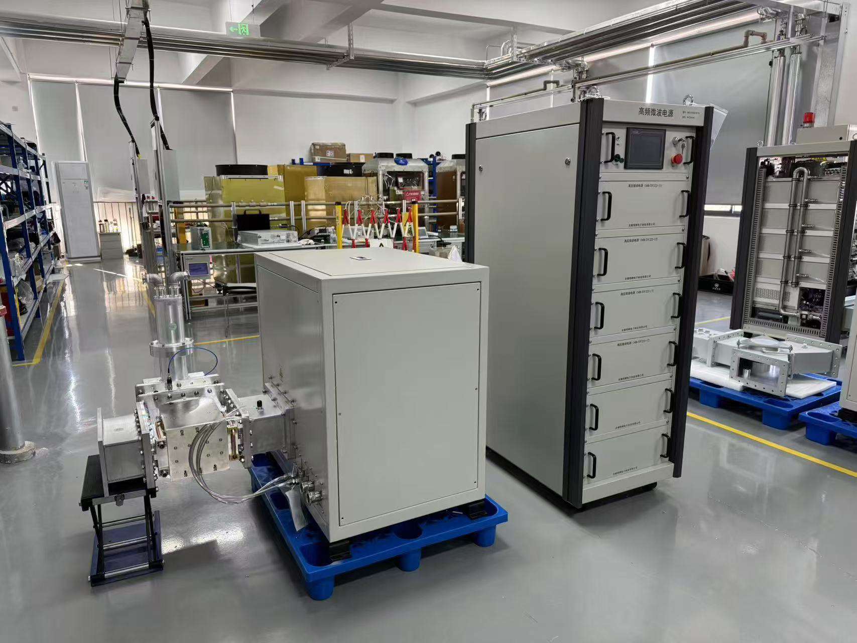
75 kW 915 MHz high-power microwave generator system

High-Power Microwave Source for Equipment Integration

Generator and subsystem configuration are selected around the complete equipment conditions rather than microwave power alone.

Frequency 915 MHz
Power Options 25 / 75 / 100 kW
Cooling Water-Cooled
Integration Project-Configured
Final power level, interfaces and supply scope are defined through project engineering review.
915 MHz High-power microwave platform
25–100 kW Published MW-P16 power scope
OEM / Subsystem Equipment integration support
Project Review Load · cooling · control · interface
Application Overview

What Does a Microwave Power Supply Do in Semiconductor Equipment?

A microwave generator is the microwave-energy source integrated into semiconductor, wafer or related advanced-material equipment. Depending on the agreed supply scope, the microwave system may also include the microwave head, isolation and monitoring components, waveguide transmission, matching components and control interfaces.

Core Function

Generate, control and deliver microwave energy

The generator provides the controlled microwave power required by the equipment. The final system configuration is selected around the application, required power, load behavior, microwave transmission path, cooling and equipment-control requirements.

Important System Boundary Microwave power is one part of the complete equipment.

Chamber design, load conditions, microwave coupling, vacuum, process control and other equipment conditions can all influence the final operating result.

From Microwave Source to Complete Equipment

The exact component set depends on the selected generator and project supply boundary.

1
Microwave Source

Microwave Generator / Power Source

Produces and controls the microwave energy supplied to the equipment.

  • Microwave power generation
  • Power control
  • Operating status
  • Equipment-level integration
2
Microwave Subsystem

Transmission, Monitoring & Matching

Project-configured components support microwave transmission, monitoring, protection and load-interface requirements.

  • Isolation / monitoring
  • Waveguide transmission
  • Matching components
  • Cooling / control interfaces
3
Complete Equipment

Semiconductor / Wafer Equipment

The microwave source operates as part of the complete equipment and process environment.

  • Process chamber / load
  • Vacuum / gas conditions
  • Wafer or material handling
  • Process-side control
Required Power Power level is selected from the complete equipment requirement.
Load Conditions Load behavior and microwave coupling affect system selection.
Cooling Cooling-water conditions are reviewed at the project level.
Equipment Control Control and communication interfaces depend on the project scope.
Direct Answer

The microwave source supplies controlled microwave energy to the equipment. It does not by itself define wafer yield, material quality or final process performance; those results depend on the complete equipment and process conditions.

915 MHz Power Selection

25 kW, 75 kW and 100 kW Microwave Power Options

SDACME's MW-P16 application scope focuses on 915 MHz high-power configurations for semiconductor, wafer and related equipment. The correct power class should be selected from the complete equipment requirement rather than nominal microwave power alone.

25 kW
915 MHz

Project-Configured Power Option

  • 915 MHz high-power platform
  • BJ9 waveguide output interface
  • Water-cooled configuration
  • OEM and subsystem integration review
25 kW Application Scope
75 kW
915 MHz

High-Power Equipment Integration

  • 915 MHz high-power platform
  • BJ9 waveguide output interface
  • Water-cooled configuration
  • Semiconductor / wafer equipment application scope
75 kW Application Scope
100 kW
915 MHz

Higher-Power Project Systems

  • 915 MHz high-power platform
  • BJ9 waveguide output interface
  • Water-cooled configuration
  • Project-specific semiconductor equipment integration
100 kW Application Scope
Power selection is an engineering decision. Final configuration depends on the equipment load, operating conditions, waveguide interface, reflected-power conditions, cooling, control requirements and agreed supply scope.
OEM Microwave Subsystem

915 MHz Microwave Power System Architecture for Semiconductor Equipment

A semiconductor-equipment microwave source normally operates as part of a larger power-delivery and machine-control architecture. The exact component set and supply boundary are confirmed at project level.

01

Microwave Generator

Generates and controls 915 MHz microwave energy for the selected equipment configuration.

25 / 75 / 100 kW
02

Microwave Head

Provides the microwave-output interface between generator hardware and the transmission path.

BJ9 interface
03

Isolation & Monitoring

Supports generator protection and forward/reflected-power monitoring according to the selected configuration.

Configuration dependent
04

Waveguide Transmission

Transfers microwave power toward the chamber or equipment load interface.

Project geometry
05

Impedance Matching

Supports load matching and management of reflected-power conditions where required.

Project option
06

Semiconductor Equipment

Process chamber, load, vacuum, gas, material handling and process-side conditions form the complete equipment environment.

Complete equipment

Control & Interlocks

HMI, remote operation, status, alarms and project interlocks are coordinated with the equipment architecture.

Cooling

Generator, microwave-head and external cooling-water conditions are reviewed for the selected configuration.

Process Conditions

Load, chamber, vacuum, gas and process conditions are project inputs because they influence the complete system design.

Typical supply boundary: generator-only, microwave subsystem and broader equipment scope can be defined according to the quotation and technical agreement. Final process performance depends on the complete equipment and process conditions, not the microwave generator alone.
OEM Integration Interfaces

Interfaces to Review Before OEM Integration

A high-power microwave source should be integrated from the equipment interfaces outward. Exact dimensions, connection details and project documents are confirmed after the selected configuration and supply scope are defined.
Electrical InputSite power conditions, electrical interface and project power-distribution requirements.
Microwave OutputBJ9 waveguide output interface for the published 915 MHz high-power range.
Waveguide PathWaveguide arrangement, routing, support and connection to the equipment load interface.
Mechanical InstallationEquipment footprint, installation space, service access and integration arrangement.
Control InterfaceLocal operation, remote-control requirements, alarms and project interlocks.
CommunicationRS485 / Modbus RTU capability on applicable configurations; other requirements are reviewed by project.
Cooling InterfaceCooling-water conditions and generator / microwave-head cooling requirements.
Safety InterlocksEquipment-level interlock categories are coordinated without exposing internal protection logic.
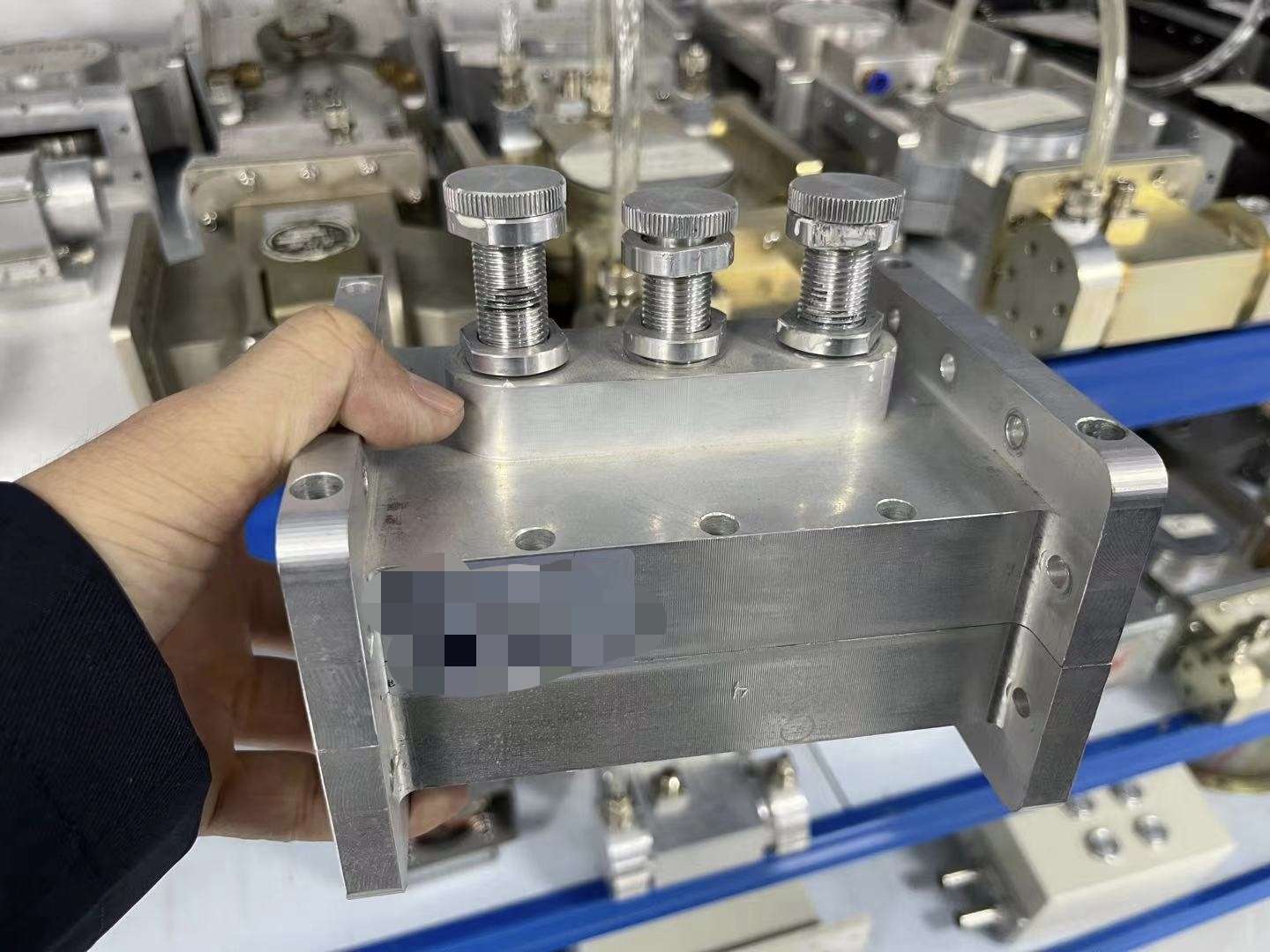
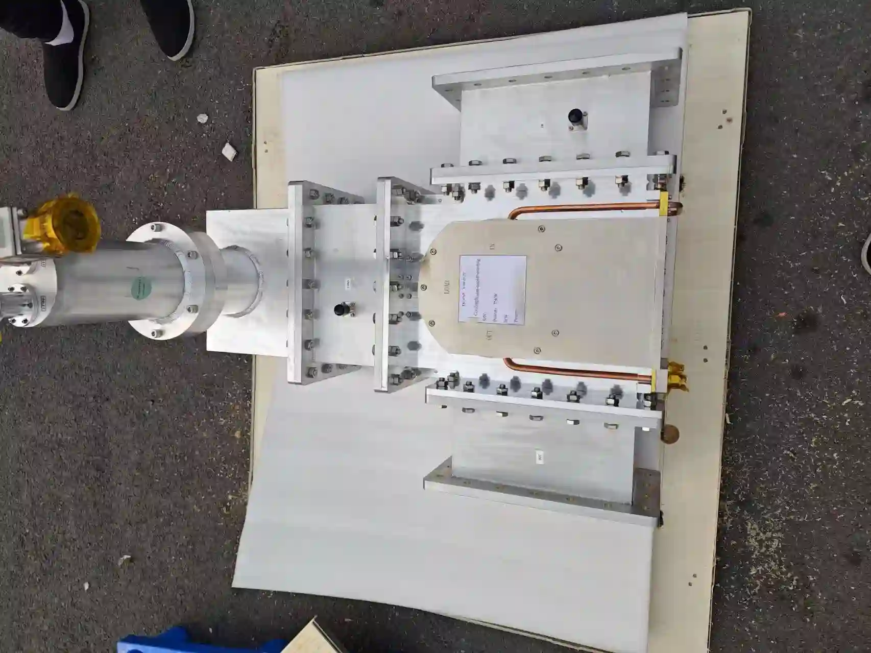
Waveguide output components for a 75 kW 915 MHz microwave generator
Representative 75 kW / 915 MHz waveguide-output hardware. Exact interface arrangement is confirmed for the selected project configuration.
Detailed interface definitions, drawings and project-specific connection information are provided during the engineering and technical-agreement process.
Cooling & Load Conditions

Key Conditions That Influence Microwave System Design

High-power microwave integration depends on more than rated output. Cooling, load behavior, reflected-power conditions, transmission geometry and operating duty should be reviewed together.

Cooling Capacity

Generator and microwave-head cooling requirements are reviewed for the selected power configuration.

Load Variation

Changes in the process load can influence microwave coupling and reflected-power conditions.

Reflected Power

Isolation, monitoring and matching components support operation under project-specific reflected-power conditions.

Waveguide & Matching

Transmission geometry and matching arrangements are reviewed with the equipment load interface.

Operating Duty

Required operating mode and duty conditions form part of generator and cooling selection.

Installation Environment

Site conditions, ambient environment and equipment arrangement should be included in project review.
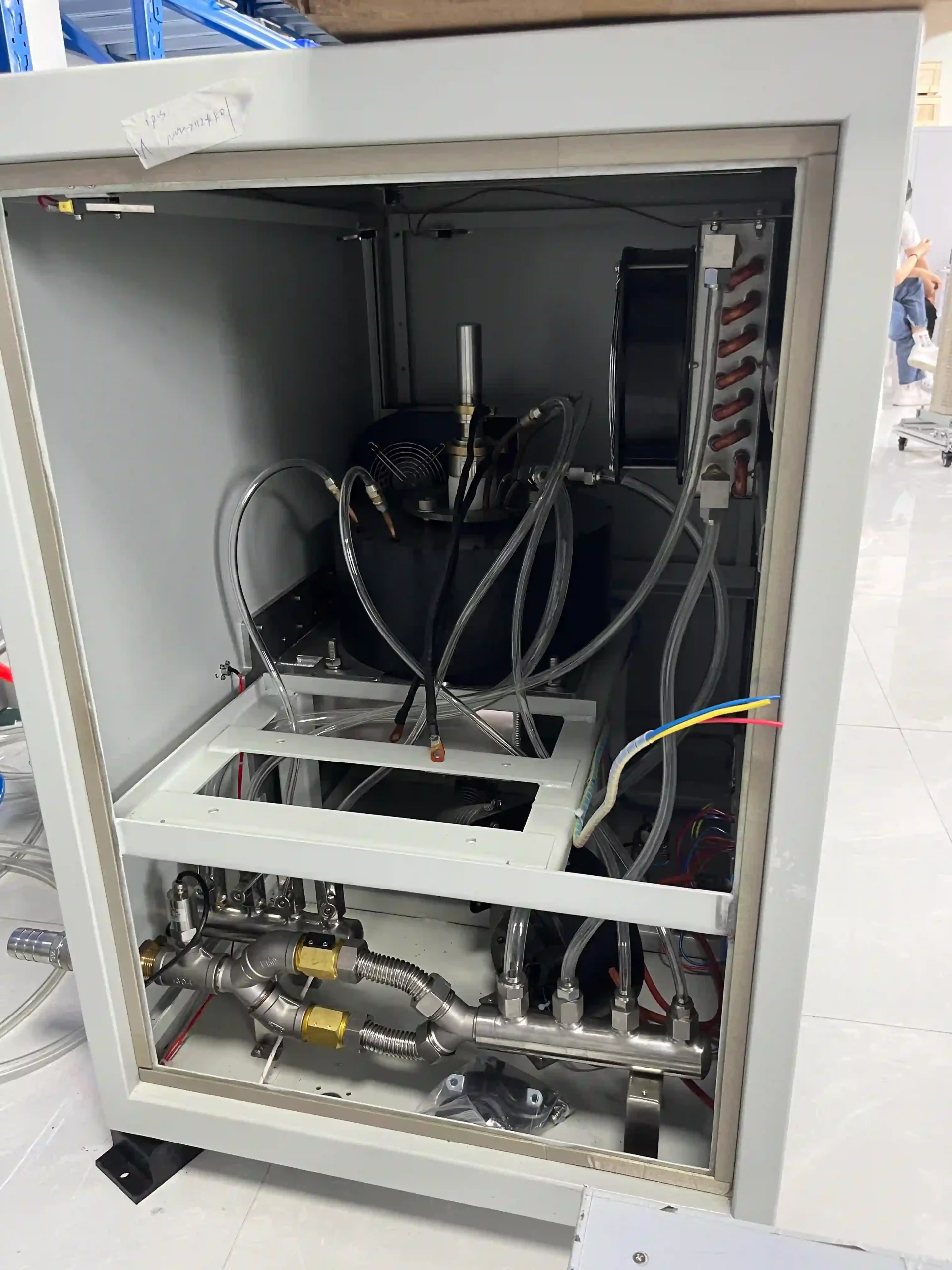
Internal cooling piping in a 75 kW 915 MHz microwave generator
75 kW / 915 MHz generator cooling hardware. External cooling-water conditions and the final cooling supply boundary are reviewed by project.
Public-page boundary: actual operating limits, protection thresholds and internal control logic are model- and project-level technical information.
Control & Equipment Integration

Integrate the Microwave Source with Your Equipment Control System

The microwave generator can operate as part of a larger OEM machine-control architecture. Applicable control functions and communication interfaces depend on the selected generator and project scope.

Local HMI Operation

Local operating and status visibility are available on applicable generator configurations.

Remote Equipment Control

Remote-control requirements can be reviewed for OEM equipment integration.

Communication

RS485 and Modbus RTU are documented for applicable models. Other interface requirements are confirmed by project.

PLC Integration

External PLC integration can be reviewed according to the equipment-control architecture.

Alarms & Status

Operating status, alarms and system feedback can support equipment-level monitoring.

Safety Interlocks

Project interlocks coordinate microwave operation with relevant machine conditions.
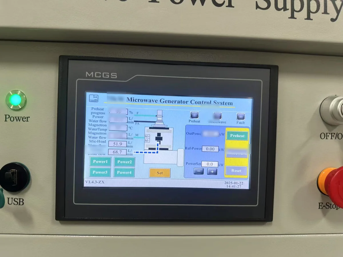
Public information describes control categories and integration capability. Register maps, I/O details, internal thresholds, terminal assignments and control sequences remain project-level technical information.
HMI control interface on a 75 kW microwave generator
75 kW microwave-generator HMI used as real equipment-control evidence. Final remote-control and communication scope depends on the selected project configuration.
Project Responsibility Boundary

Typical Microwave Supply Scope and Complete-Equipment Boundary

The microwave system can be supplied at different integration levels. The final boundary is defined by the quotation, technical agreement and complete equipment requirement.

Typical Microwave Supply Scope
  • 915 MHz microwave generator
  • Microwave head
  • Isolation and monitoring components
  • Waveguide components
  • Matching components where required
  • Control-system integration
  • Cooling-interface review
  • Generator / subsystem FAT and documentation
  • OEM engineering support
Complete Equipment / Process-Side Scope
  • Process chamber and microwave load
  • Vacuum-system requirements
  • Process-gas delivery and conditions
  • Wafer or material handling
  • Process recipe and process parameters
  • Process-side control system
  • Overall machine architecture
  • Final material and process performance
Final project boundary: process-side equipment may be included in a broader project scope where agreed. Wafer yield, material quality and final process performance depend on the complete equipment and process conditions and are not determined by microwave-generator rated power alone.
OEM Project Checklist

Information Required for Engineering Review

Providing the main equipment conditions allows the applicable generator, integration interfaces and project supply scope to be reviewed more efficiently.

01

Equipment / Application Type

Describe the semiconductor, wafer or advanced-material equipment.

02

Required Microwave Power

Provide target power or existing operating range where known.

03

Existing Frequency

State the current or required microwave frequency.

04

Chamber / Load Information

Describe the microwave load and relevant chamber conditions.

05

Waveguide / Flange Interface

Provide existing connection information where available.

06

Electrical Supply

State available site power and relevant electrical conditions.

07

Cooling-Water Conditions

Provide available cooling arrangement and site conditions.

08

Control / Communication

Define local, remote, PLC or communication requirements.

09

Operating Duty

Describe expected operating mode and duty conditions.

10

Quantity

Indicate prototype, single-unit or production quantity.

11

Destination Country

Required for project, logistics and site-condition review.

12

FAT / Documentation Requirements

List requested test, acceptance and technical-document requirements.

Engineering input: these conditions help define the applicable generator, interfaces and project supply boundary.
Engineering Verification

Generator and Subsystem Verification Before Equipment Integration

Factory testing and project documentation support generator and microwave-subsystem verification before integration into the customer's complete semiconductor equipment.
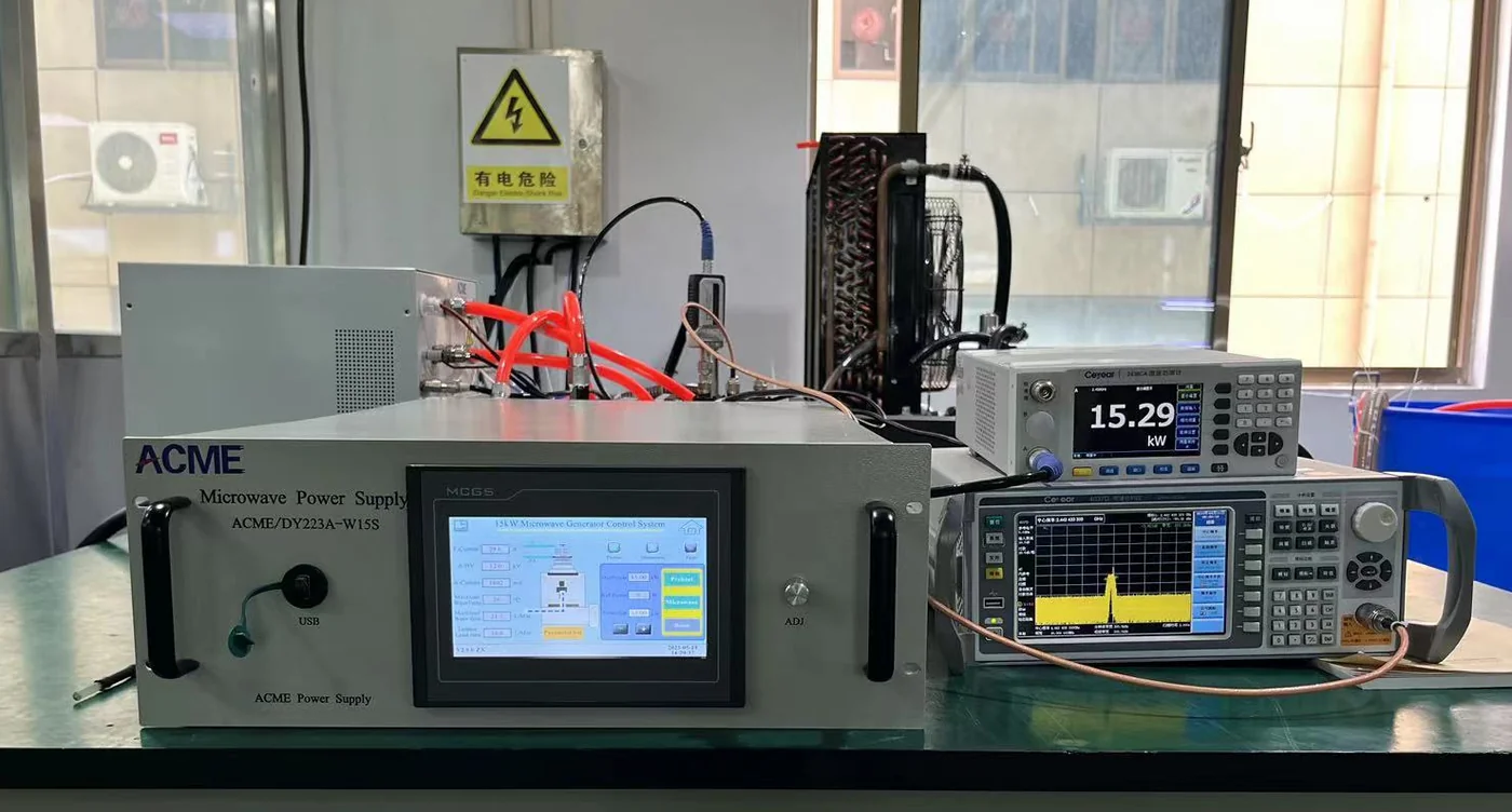
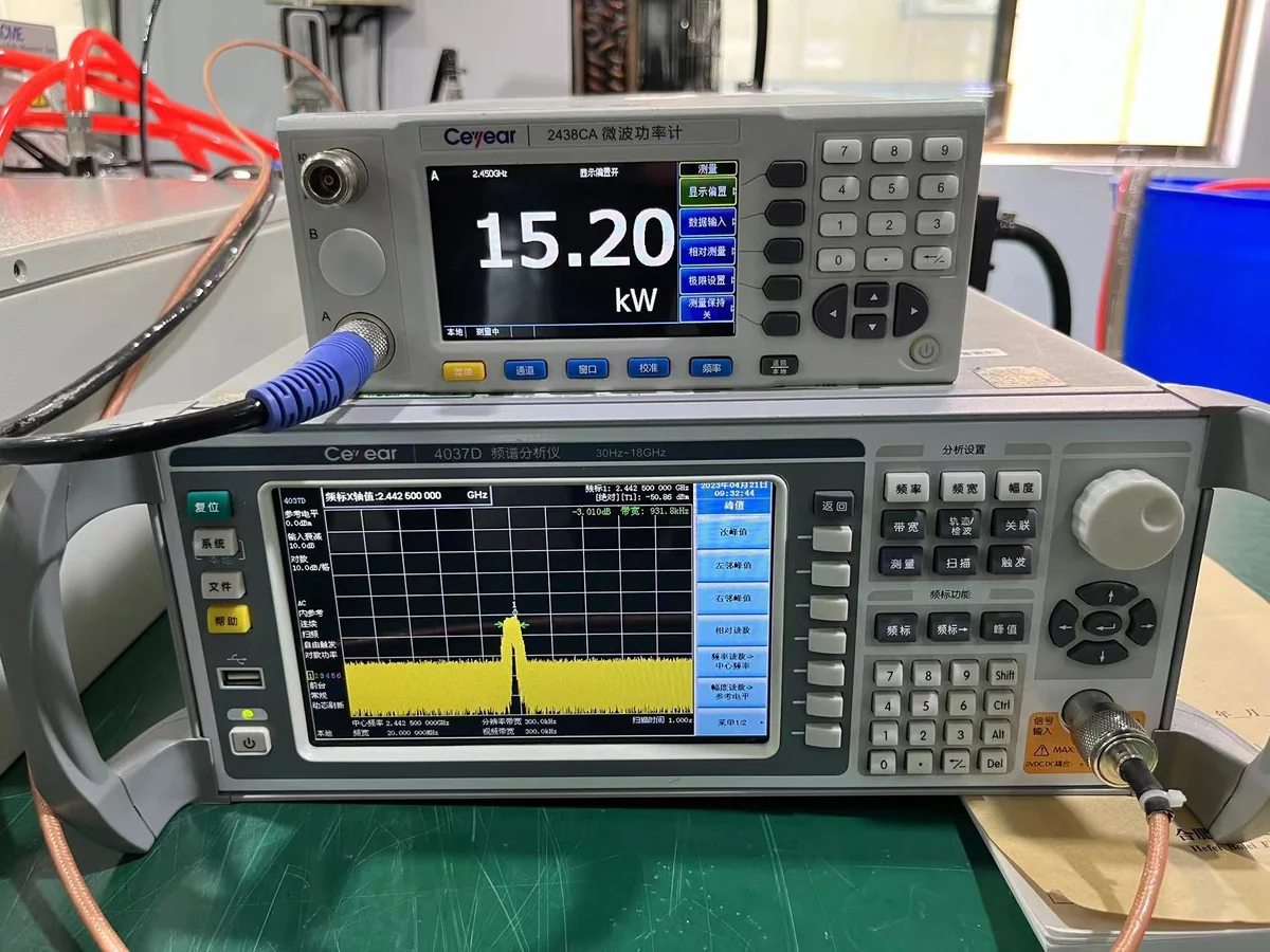
FAT boundary: test scope, test conditions, acceptance criteria and required records are defined according to the selected generator, project requirements and technical agreement. Generator-level tests do not by themselves represent wafer-process or production-yield validation.
FAQ / GEO Direct Answers

Frequently Asked Questions About Microwave Power for Semiconductor Equipment

These answers explain the main selection and integration questions before a semiconductor-equipment microwave project enters detailed engineering review.

What microwave frequency is used for SDACME semiconductor equipment projects?
For the current MW-P16 high-power application scope, the primary published direction is 915 MHz. The page focuses on 25 kW, 75 kW and 100 kW configurations. Final frequency and power selection should still be reviewed against the complete equipment conditions.
Can a 915 MHz microwave generator be integrated into wafer equipment?
Yes, 915 MHz high-power microwave generators can be reviewed for semiconductor and wafer-equipment integration. The project should confirm the required power, chamber or load conditions, waveguide interface, cooling, control and overall machine architecture.
What power levels are available for MW-P16 semiconductor applications?
The MW-P16 published application scope focuses on 25 kW, 75 kW and 100 kW at 915 MHz. Final selection depends on the equipment requirement rather than power rating alone.
How do I choose between 25 kW, 75 kW and 100 kW?
Selection should consider required microwave power, load behavior, chamber interface, reflected-power conditions, waveguide configuration, cooling, operating duty and equipment-control requirements. SDACME reviews these conditions before confirming the applicable configuration.
Can SDACME supply more than the microwave generator?
Yes. Depending on project scope, supply can extend from generator-only to a microwave subsystem including microwave-head, monitoring, waveguide, matching, control-integration and related engineering support. The final supply boundary is defined by quotation and technical agreement.
What information is required for OEM integration?
Useful project inputs include equipment type, required microwave power, existing frequency, chamber or load information, waveguide or flange interface, electrical supply, cooling conditions, control and communication requirements, operating duty, quantity, destination and FAT/documentation requirements.
Can an existing microwave generator be replaced in semiconductor equipment?
Replacement can be evaluated when the existing generator, frequency, power level, waveguide interface, electrical conditions, cooling and control requirements are known. Compatibility should be confirmed before treating a replacement as drop-in.
Does higher microwave power improve wafer yield or process results?
Not by itself. Rated microwave power alone does not determine wafer yield, material quality or process performance. Final results depend on the complete equipment, chamber or load, microwave coupling, cooling, control and process conditions.
Direct answer: a microwave generator is the microwave-energy source within a larger semiconductor-equipment system. Selecting the correct generator requires matching frequency, power and system interfaces to the complete equipment rather than assuming that higher microwave power alone produces a better process result.
Project RFQ

Discuss Your Semiconductor Equipment Microwave Requirements

Share the main equipment conditions and SDACME can review the applicable 915 MHz microwave generator, subsystem interfaces and project supply scope.

Application / Equipment
Required Microwave Power
Existing Generator / Frequency
Waveguide / Flange Interface
Chamber / Load Information
Cooling Conditions
Control / Communication
Operating Duty
Quantity
Destination Country
FAT Requirements
Technical Documents

Final generator selection, interfaces, supply scope and acceptance requirements are confirmed according to the project quotation and technical agreement.

75 kW 915 MHz high-power microwave generator for equipment integration
915 MHz High-Power Microwave Platform 25 kW, 75 kW and 100 kW MW-P16 application configurations are reviewed according to the complete semiconductor-equipment requirement.