MARINE STATIC FREQUENCY CONVERTER

Marine Frequency Converter for 50Hz and 60Hz Vessel Power

Convert the available shore-side electrical supply to the voltage, frequency and phase sequence required by the vessel.

SDACME supplies project-specific marine frequency converters for ports, shipyards, dry docks, vessel maintenance and electrical testing. Each converter is configured around the available grid, vessel load, required output and selected equipment scope.

50Hz to 60Hz / 60Hz to 50Hz

Configure frequency conversion for different shore-grid and vessel electrical standards.

Low- and High-Voltage Configurations

300–3000kVA low-voltage reference range and project-engineered MVA-class high-voltage systems.

Voltage and Phase Matching

Configure output voltage and phase sequence for the required vessel connection.

Flexible Supply Scope

Select a standalone marine converter or an integrated shore power conversion package.
PROJECT-CONFIGURED EQUIPMENT Static Frequency Conversion for Vessel Power
Marine static frequency converter cabinet for vessel power conversion
FREQUENCY 50Hz ↔ 60Hz
VOLTAGE CLASS LV and HV
INSTALLATION Indoor / Outdoor / Containerized
INITIAL PROJECT INFORMATION Provide the input voltage and frequency, required vessel output, estimated capacity and main load information.
Prepare Your Inquiry
PRODUCT OVERVIEW

What Is a Marine Frequency Converter?

A marine frequency converter matches the available shore-side electrical supply to the power required by a vessel electrical system.

A marine frequency converter is a static power-conversion device that receives an available three-phase AC supply and delivers the voltage, frequency and phase sequence required by the vessel.

In shore power applications, it is used when the local port or shipyard grid and the vessel distribution system operate with different electrical parameters. A common application is converting 50Hz shore power into the 60Hz supply required by the vessel.

Frequency conversion is completed by the converter. Voltage matching can be achieved through converter output control, transformer configuration or a coordinated combination of both.

The converter can be supplied as core equipment or incorporated into a larger shore power package with transformers, switchgear, monitoring, protection and vessel connection equipment.

RELATED PRODUCT FAMILY Explore Commercial Shore Power Systems
CONVERSION PURPOSE Match the Shore Supply to the Vessel
AVAILABLE INPUT Shore Grid Voltage · Frequency · Capacity
POWER CONVERSION Marine Frequency Converter Frequency · Voltage · Phase Sequence
REQUIRED OUTPUT Vessel Power Matched electrical supply
01

Frequency Conversion

Configure 50Hz-to-60Hz or 60Hz-to-50Hz operation according to the shore grid and vessel electrical system.

02

Voltage Matching

Match the vessel voltage through converter control, transformer configuration or a coordinated combination.

03

Phase-Sequence Adjustment

Configure the output phase sequence for vessel connection and commissioning requirements.

04

Flexible Equipment Scope

Supply the converter alone or combine it with transformers, switchgear, protection, monitoring and connection equipment.

IN SIMPLE TERMS

The converter matches the available shore grid to the electrical power required by the vessel.

50HZ / 60HZ CONVERSION

Match the Shore Grid to the Vessel Power System

Shore power projects frequently involve differences in frequency, voltage, phase sequence and available grid capacity. The converter is configured around the actual shore input and vessel output requirements.

COMMON MARINE APPLICATION 50Hz → 60Hz

50Hz to 60Hz Shore Power Converter

A 50Hz to 60Hz shore power converter allows a vessel designed for 60Hz operation to use power from a 50Hz port or shipyard grid. This is one of the most common applications for a marine frequency converter in international ports and vessel-service facilities.

SHORE INPUT 50Hz Port or shipyard grid
VESSEL OUTPUT 60Hz Required vessel operation
REVERSE FREQUENCY CONVERSION 60Hz → 50Hz

60Hz to 50Hz Shore Power Converter

A 60Hz to 50Hz shore power converter is configured when the available shore supply is 60Hz and the vessel requires 50Hz power. The same project review covers output voltage, phase sequence, load behaviour and connection requirements.

SHORE INPUT 60Hz Available shore supply
VESSEL OUTPUT 50Hz Required vessel power
01

Frequency Conversion

Configure 50Hz-to-60Hz or 60Hz-to-50Hz output for the vessel electrical system.

02

Voltage Matching

Match output voltage through converter control, transformer configuration or a coordinated combination.

03

Phase-Sequence Adjustment

Adjust the output phase sequence through the control system for vessel connection and commissioning.

04

Load-Based Rating

Select converter capacity from rated load, rated voltage, rated current, inrush current and simultaneous operating loads.

CONFIGURATION PRINCIPLE The correct solution is selected from the complete electrical requirement, not from rated kVA alone.
HOW IT WORKS

How a Shore Power Static Frequency Converter Works

The shore frequency converter transforms the incoming AC supply through a controlled power-conversion process.

POWER FLOW From Shore Input to Vessel Load
STATIC POWER CONVERSION
01 Shore Input Available AC power
02 Input Protection Switching and protection
03 Rectifier AC converted to DC
04 DC Link Intermediate power stage
05 IGBT Inverter Controlled AC output
06 Output Matching Voltage and filtering
07 Output Protection Controlled vessel supply
08 Vessel Load Required marine power

The rectifier converts the incoming AC supply into DC power. The DC link stabilizes the intermediate power stage, and the IGBT inverter produces a controlled AC output at the required frequency and voltage.

LOW-VOLTAGE CONVERSION

IGBT Static Frequency-Conversion Cabinet

Low-voltage shore power converters generally use an IGBT static frequency-conversion cabinet. The converter, HMI, protection, cooling and communication functions are integrated according to the selected capacity and enclosure design.

IGBT Conversion HMI Control Protection Cooling
HIGH-VOLTAGE CONVERSION

Coordinated Multi-Cabinet System

High-voltage shore power conversion is engineered as a coordinated multi-cabinet system. A typical configuration can include input and output switchgear, phase-shifting transformers, converter power-unit cabinets, isolation transformers, protection panels, neutral-grounding equipment and auxiliary control systems.

In a ship frequency converter application, modular power units, phase-shifting rectification and multi-level output technology can be used to support MVA-class capacity and high-voltage waveform performance.
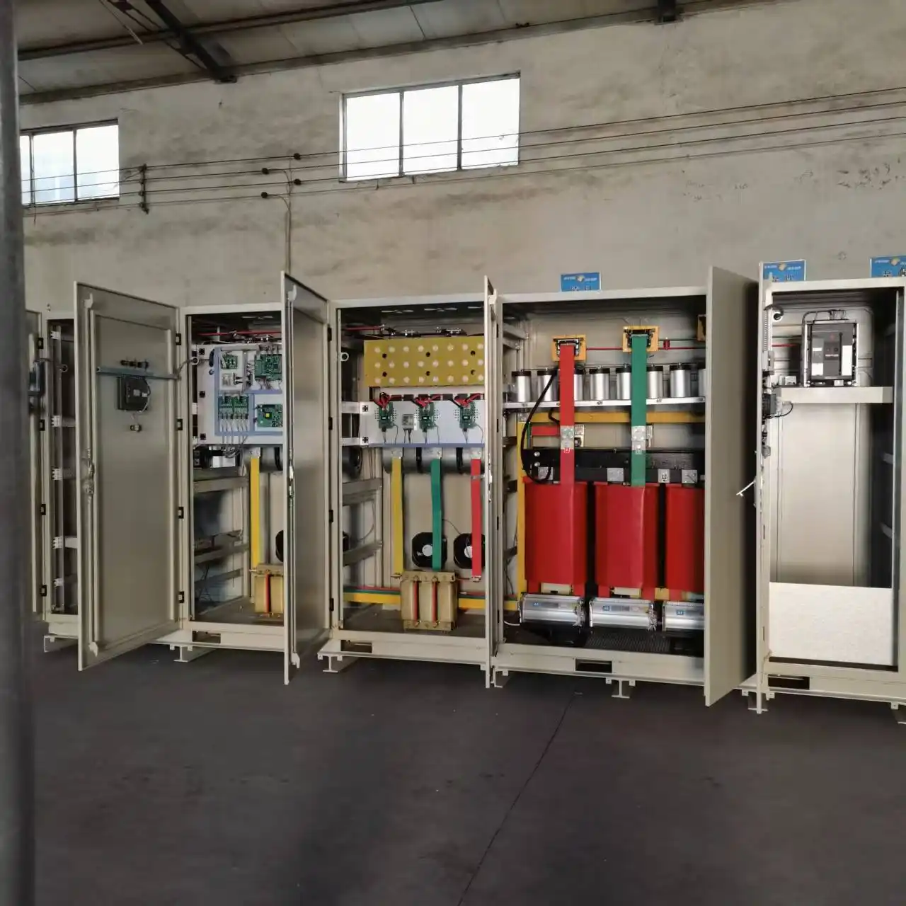
CONFIGURATION APPROACH Power topology and cabinet arrangement are selected according to the required voltage class and capacity.
INPUT & OUTPUT

Typical Shore Power Conversion Configurations

Input voltage, output voltage and frequency are configured according to the available shore grid and the vessel electrical system. The examples below show common project directions.

CONFIGURATION PATH Shore Input → Power Conversion → Vessel Output
PROJECT-SPECIFIC
SHORE-SIDE INPUT Available Grid Supply
  • Low voltage: 380–440V
  • High voltage: 10kV
  • 50Hz or 60Hz input
POWER CONVERSION Converter & Transformer
  • 50Hz ↔ 60Hz conversion
  • Output-voltage matching
  • Phase-sequence adjustment
VESSEL OUTPUT Required Marine Supply
  • 380–480V low voltage
  • 6kV, 6.6kV or 11kV
  • 50Hz or 60Hz output
REFERENCE CONFIGURATIONS

Common Input and Output Directions

Each row represents a typical project direction rather than a fixed standard model.

Typical shore power frequency converter input and output configurations
Voltage ClassShore-Side InputRequired Vessel OutputTypical Configuration
LV 380V / 50Hz 380–480V / 60Hz Low-voltage frequency conversion; 300–3000kVA reference range
LV 400V or 415V / 50Hz 440V / 60Hz Voltage and frequency conversion
LV 440V / 60Hz 400V or 415V / 50Hz Reverse-frequency conversion
HV 10kV / 50Hz 6kV / 50Hz or 6.6kV / 60Hz High-voltage shore power conversion
HV 10kV / 50Hz 6.6kV or 11kV / 60Hz High-voltage converter with isolation transformer
HV–LV 10kV / 50Hz 400V / 50Hz or 440V / 60Hz Converter and transformer package
FINAL CONFIGURATION

The Electrical Conditions Are Reviewed as One System

The final configuration is selected from capacity, grid conditions, vessel voltage, earthing method, transformer arrangement, cable system, protection requirements and the required operating sequence.

01 Capacity
02 Grid Conditions
03 Vessel Voltage
04 Earthing Method
05 Transformer Arrangement
06 Cable System
07 Protection Requirements
08 Operating Sequence
TECHNICAL SPECIFICATIONS

Typical Technical Specifications

Shore power frequency converters are configured for the electrical conditions, capacity and installation requirements of each project.

AVAILABLE CONFIGURATION

Shore Power Converter Technical Range

LV & HV
Typical shore power frequency converter technical specifications
ParameterAvailable Direction
Frequency Conversion 50Hz to 60Hz; 60Hz to 50Hz
Low-Voltage Input / Output Typical project voltages include 380V, 400V, 415V, 440V, 450V and 480V
High-Voltage Classes Typical project voltage classes include 6kV, 6.6kV, 10kV and 11kV
Low-Voltage Capacity 300–3000kVA reference range
High-Voltage Capacity Project-engineered MVA-class systems
Phase Three-phase; neutral arrangement configured for the project
Low-Voltage Power Conversion IGBT static frequency-conversion cabinet
High-Voltage Topology Multi-cabinet conversion system with project-configured transformers, switchgear and protection
Control Local HMI and PLC-based control
Communication RS232, RS485, CAN and Profibus; integration with PLC, HMI or SCADA systems
Installation Indoor cabinet, outdoor enclosure or containerized integration
Cooling Air cooling, HVAC or project-specific thermal management
Protection Electrical, converter, transformer and system protection configured for the selected scope
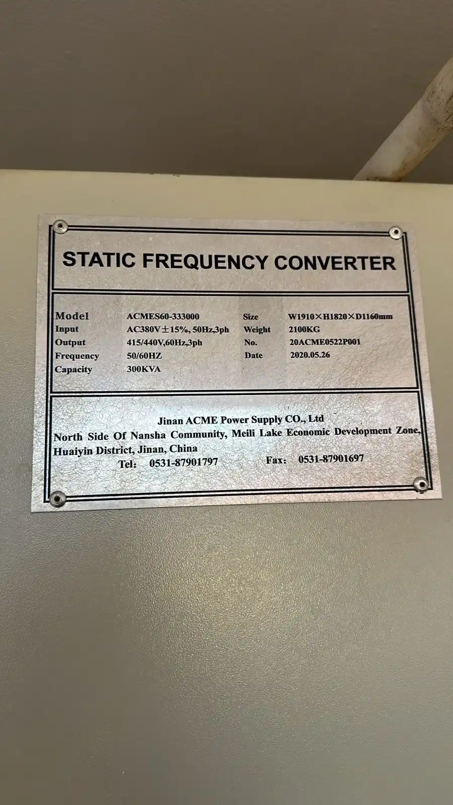
300 kVA static frequency converter nameplate
EQUIPMENT REFERENCE 300kVA Static Frequency Converter Nameplate
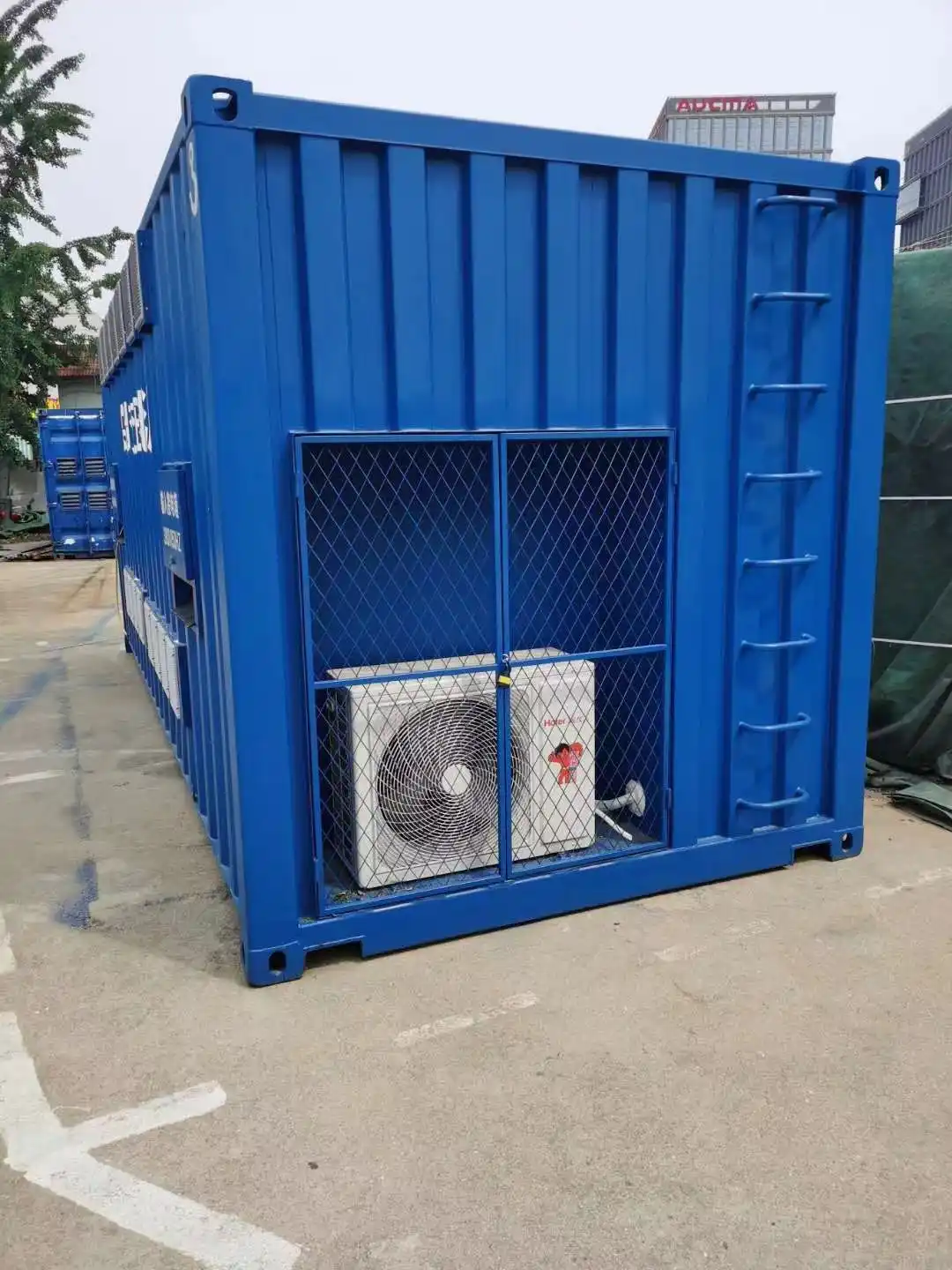
Shore power converter cooling system
THERMAL MANAGEMENT Shore Power Converter Cooling System
PROJECT CONFIGURATION Capacity, enclosure and thermal management are selected for the electrical load and installation environment.
HIGH-VOLTAGE REFERENCE

Typical High-Voltage Performance

MVA-CLASS
Typical high-voltage shore power frequency converter performance
ParameterTypical Value
Reference Input 10kV, three-phase, 50/60Hz
Input Voltage Tolerance −15% to +15%
Input Frequency Tolerance −5% to +5%
Reference Output 6.6kV / 60Hz or 11kV / 60Hz
Frequency Accuracy 0.01Hz
Three-Phase Voltage Imbalance ≤2%
Load Stability Within ±1%
No-Load Output Voltage Harmonics ≤3% without an additional filter
Input Power Factor Above 0.96 at loads above 20%
Input Current Harmonics Below 3% at rated load
Overload Capability Configured for the selected capacity, load profile and protection settings
SPECIFICATION BASIS Final equipment specifications are defined by the selected voltage class, capacity, load characteristics and project configuration.
CONTROL & PROTECTION

Control, Protection and Operating Flexibility

Stable vessel power requires coordinated converter control, vessel connection, load response, communication and electrical protection.
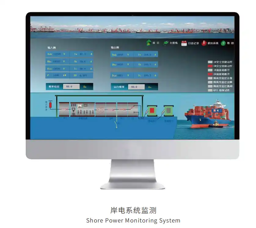
HMI control screen for a shore power frequency converter
LOCAL OPERATING INTERFACE Shore Power Frequency Converter HMI

HMI and PLC-Based Converter Control

The marine shore power converter can be operated through a local HMI with PLC-based control logic. The interface provides direct access to operating status, electrical parameters, alarms and configured control functions.

Output voltage and frequency display
Input and output current monitoring
Converter operating status
Alarm and fault information
Local start, stop and reset functions
Voltage Frequency Current Status Alarms

Output Adjustment for Vessel Connection

Output settings and operating functions are configured around the vessel electrical requirements and the commissioning sequence.

Voltage & Frequency Setting

Set the required output values through the local HMI within the configured operating range.

Output Fine Adjustment

Fine-tune the output during commissioning and vessel connection.

Phase-Sequence Adjustment

Adjust the output phase sequence through the control system without changing the external cable order.

Reverse-Power Handling

Add reverse-power detection, control or trip logic when required by the operating sequence.

OPERATING CONTROL PATH From Operator Setting to Vessel Supply
OPERATOR INPUT HMI Setting
CONTROL LOGIC PLC Processing
POWER CONVERSION Converter Output
REQUIRED SUPPLY Vessel Connection
COORDINATED PROTECTION Converter and Vessel-Supply Protection
Overcurrent
Overload
Short Circuit
Overvoltage
Undervoltage
Frequency Fault
Current Imbalance
Phase Conditions
Overtemperature

Electrical Protection and Fault Records

Protection settings are configured for the selected converter, vessel load conditions and operating sequence. The control system can respond to abnormal electrical or thermal conditions through alarms, controlled shutdown or trip logic.

Operating history, alarm records and fault information can support commissioning, maintenance and troubleshooting. Remote diagnostic access can also be included in the project scope.

01 Operating History
02 Alarm Records
03 Fault Information
04 Remote Diagnostics

Connect the Converter to the Shore Power Control System

Communication interfaces can be configured for integration with PLC, HMI or SCADA systems. Available communication options include RS232, RS485, CAN and Profibus.

Remote monitoring, operating permissions, interlocks and data exchange are defined according to the selected shore power architecture and project scope.

RS232 RS485 CAN Profibus
SYSTEM INTEGRATION Converter Communication Architecture
FIELD EQUIPMENT Frequency Converter Electrical parameters and operating status
LOCAL CONTROL PLC and HMI Control logic, interlocks and local operation
SUPERVISORY SYSTEM SCADA Monitoring, records and remote supervision
PROJECT-SPECIFIC CONTROL Protection thresholds, interlocks, communication interfaces and remote-control permissions are configured for the required operating conditions.
Discuss Your Requirements
SUPPLY SCOPE

Standalone Converter or Integrated Shore Power Package

SDACME can configure the supply around the customer’s existing infrastructure and required project scope.

01
CORE EQUIPMENT SUPPLY Standalone Frequency Converter

For projects where transformers, switchgear, cables and shore connection equipment are already available.

02
COORDINATED SYSTEM SUPPLY Integrated Power-Conversion Package

For projects requiring coordinated conversion, transformation, switching, protection and monitoring.

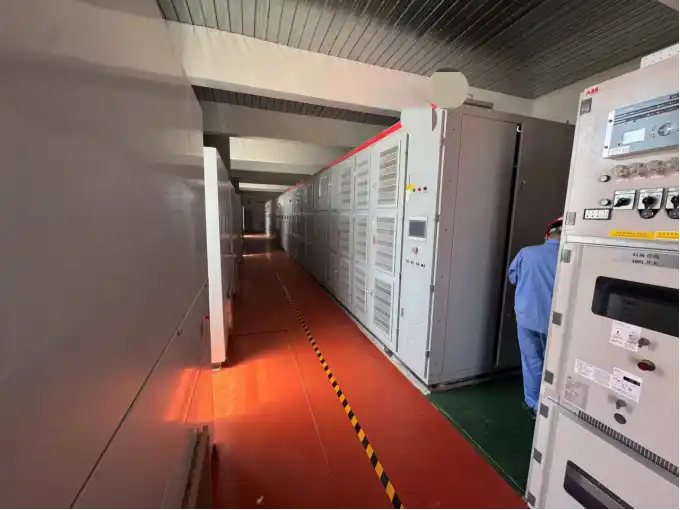
High-voltage shore power converter cabinet lineup
INTEGRATED HIGH-VOLTAGE CONFIGURATION Shore Power Converter Cabinet Lineup

Integrated Power-Conversion Package

An integrated shore power package is suitable when frequency conversion must be coordinated with voltage transformation, switching, protection, grounding, monitoring or shore connection equipment.

The system can be supplied as an indoor installation, outdoor enclosure or containerized shore power package, according to the project environment and connection requirements.

Coordinated converter and transformer configuration
Low-voltage or high-voltage switchgear integration
Protection, grounding and monitoring equipment
Indoor, outdoor or containerized enclosure

Standalone Frequency Converter

Standalone supply is suitable when transformers, switchgear, cables and shore connection equipment are already included in the customer’s infrastructure or local project scope.

The converter is supplied as the core frequency-conversion equipment with its operating, protection and cooling functions.
01 Frequency converter cabinet
02 Rectifier and inverter power stage
03 Local HMI and PLC control
04 Converter protection and cooling
05 Basic communication interface
06 Technical documentation
STANDALONE SUPPLY SCOPE Core Frequency-Conversion Equipment
MAIN EQUIPMENT Converter Cabinet
POWER STAGE Rectifier + IGBT Inverter
OPERATION HMI + PLC Control
Protection Cooling Communication Documentation
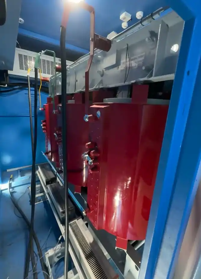
Input or output transformer for shore power conversion
VOLTAGE TRANSFORMATION Input or Output Transformer

Voltage Transformation and Electrical Isolation

Transformer equipment can be coordinated with the frequency converter when the shore grid voltage and vessel distribution voltage are different.

The selected transformer arrangement depends on the voltage class, converter topology, isolation requirements, grounding method and required output.

Input or Phase-Shifting Transformer
Isolation or Output Transformer
Neutral-Grounding Equipment
Harmonic-Filtering Equipment

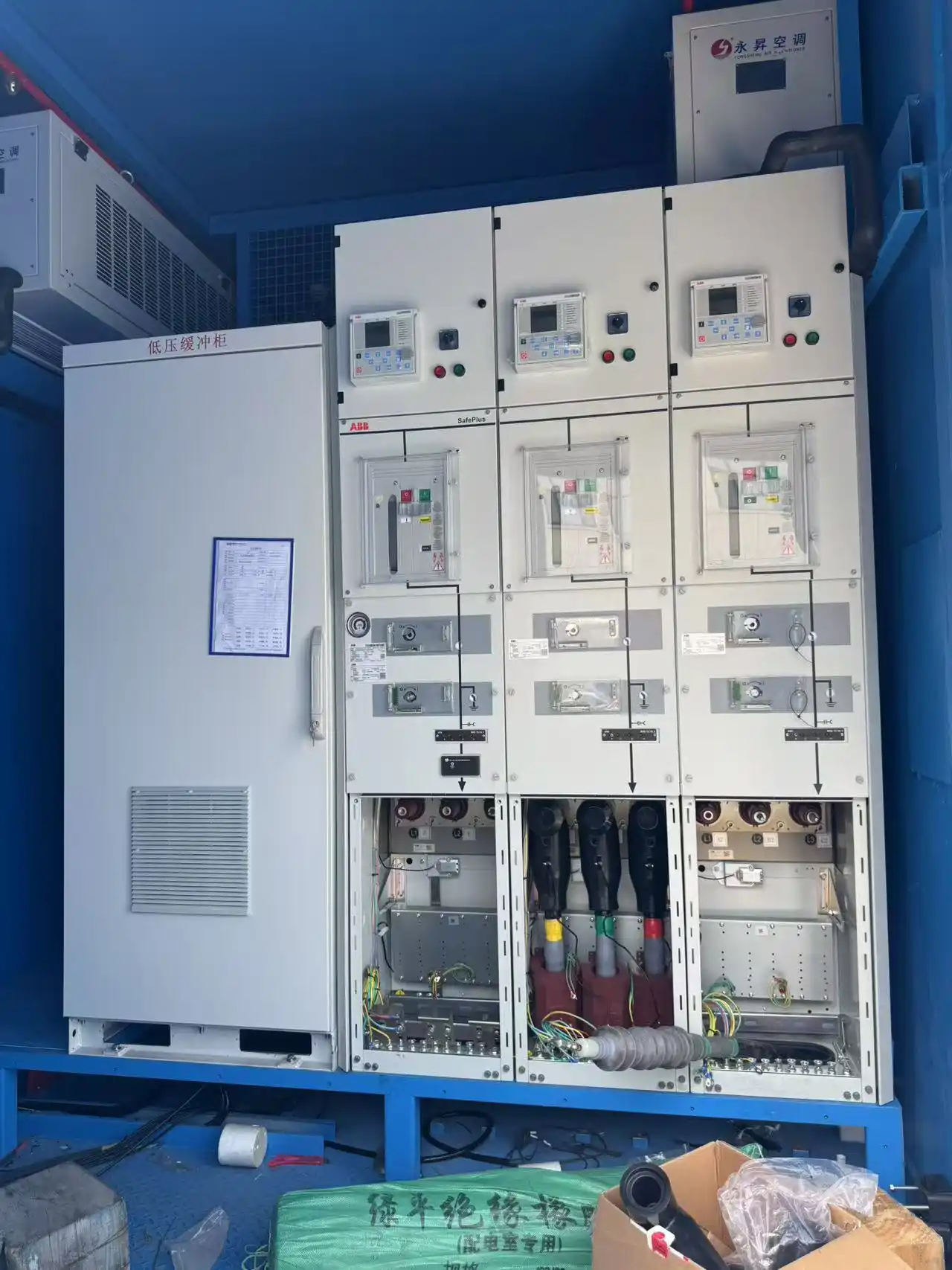
Switchgear, Protection and Shore Connection Equipment

The integrated supply can include the switching, metering, protection and control equipment required to connect the shore grid, converter and vessel distribution system.

The final equipment combination is configured according to the required voltage class, operating sequence and installation form.
MV or LV switchgear
Metering and protection panels
PLC, HMI and SCADA integration
Shore socket boxes and cables
Cable-management equipment
Indoor, outdoor or containerized enclosure
Shore power switchgear integration
SWITCHING AND PROTECTION Shore Power Switchgear Integration
SITE SERVICES

Installation, SAT, Commissioning and Training

Site installation, site acceptance testing, commissioning and operator training can be included according to the project scope and site conditions.

01 Site Installation
02 Site Acceptance Testing
03 System Commissioning
04 Operator Training
MANUFACTURING & FAT

Manufacturing, Assembly and Factory Acceptance Testing

Equipment assembly, internal wiring, transformer and switchgear integration, container installation, power-on inspection and project-specific factory acceptance testing can be completed before shipment.

01 Cabinet Assembly Mechanical and component installation
02 Internal Wiring Busbar, terminal and connection work
03 System Integration Transformer, switchgear and enclosure
04 Power-On Inspection Control and operating verification
05 Factory Acceptance Test Agreed inspection and test scope
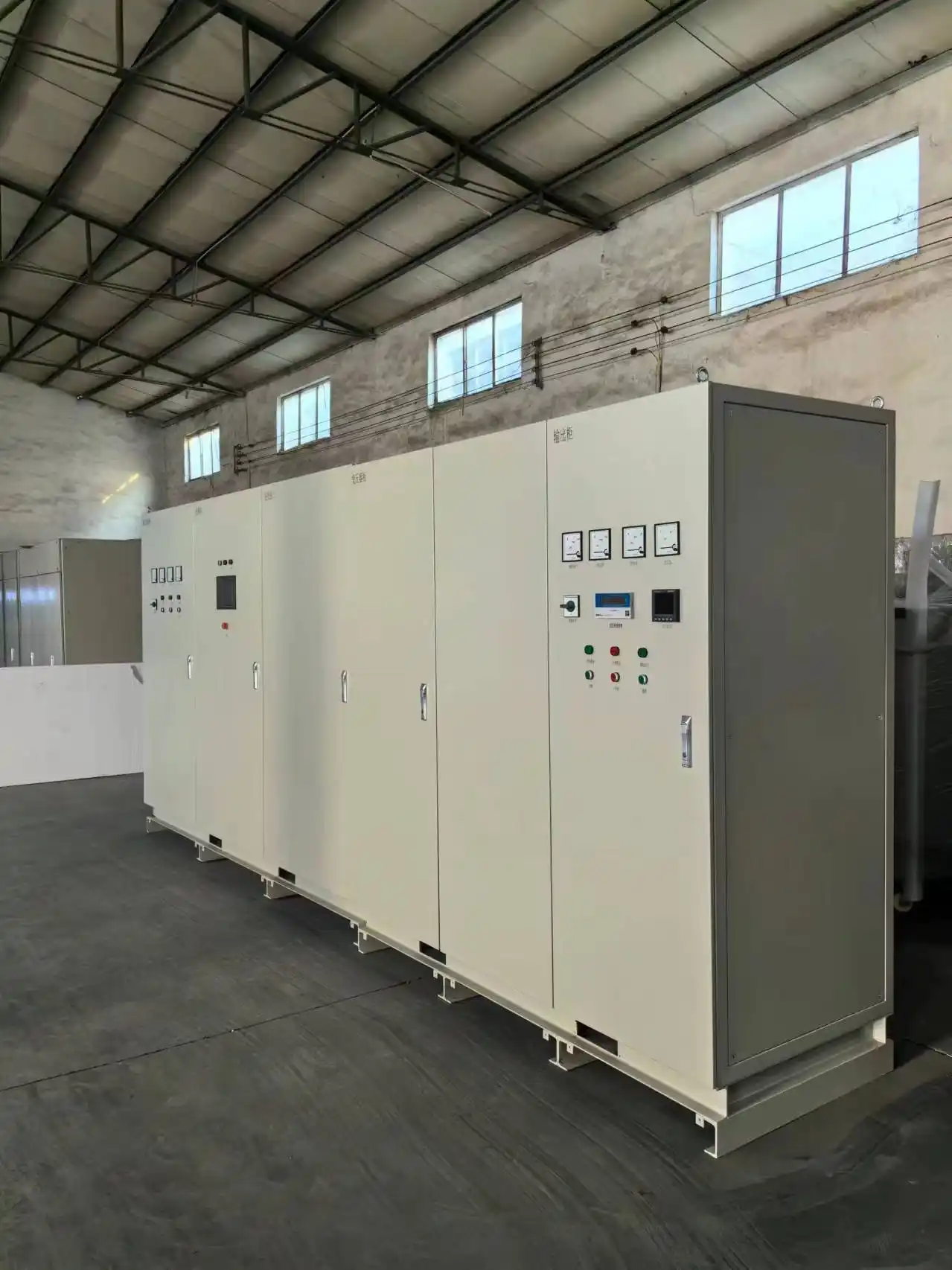
Shore power frequency converter assembly in the factory
FACTORY ASSEMBLY Shore Power Frequency Converter Assembly

Assembly and System Integration

The manufacturing scope is arranged around the selected converter configuration, voltage class, enclosure type and auxiliary equipment.

Converter cabinets, power units, control equipment, transformers, switchgear and selected auxiliary systems can be assembled and integrated before shipment.

Cabinet construction and component installation
Rectifier and inverter power-stage assembly
Transformer and switchgear integration
HMI, PLC and protection-panel installation
Indoor, outdoor or containerized assembly
Pre-shipment power-on inspection

Routine Inspection and Electrical Testing

Factory inspection covers equipment construction, internal connections, electrical performance, protection functions and agreed operating checks.

01 Visual Inspection

Cabinets, components, labels and terminals.

02 Wiring Checks

Internal wiring and electrical connections.

03 Insulation Tests

Insulation and withstand-voltage testing.

04 Output Voltage

Voltage output and regulation accuracy.

05 Output Frequency

Verification of the configured frequency.

06 Dynamic Response

Response under the agreed test conditions.

07 Protection Functions

Alarm, trip and protection-function checks.

08 Efficiency

Efficiency testing within the FAT scope.

09 Noise

Equipment noise testing.

10 HMI & Communication

Display, alarms, records and interfaces.
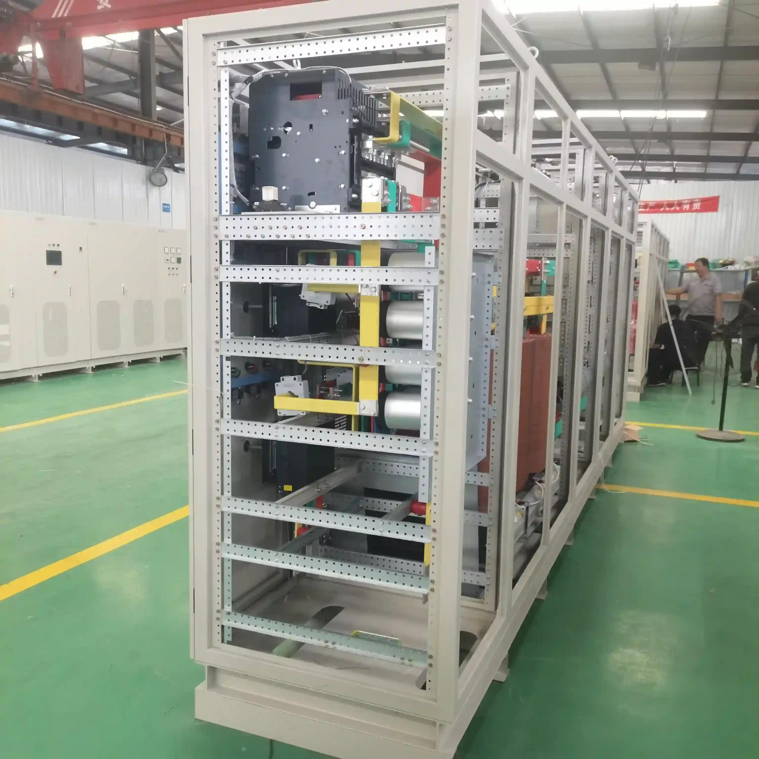
Internal wiring and component inspection of a shore power converter
INTERNAL QUALITY INSPECTION Wiring and Component Inspection
Factory acceptance test for a shore power frequency converter
FACTORY ACCEPTANCE TEST Shore Power Converter FAT

Project-Specific Factory Acceptance Testing

Rated-load or project-specific load testing can be arranged according to the agreed FAT scope, available load equipment and technical requirements.

Short-circuit high-current testing can also be applied where it matches the approved test method.

Load Testing

Rated-load or project-specific operating tests.

Agreed Acceptance Values

FAT items and acceptance values are agreed before testing.

Customer Witnessing

Witnessing can be arranged at the factory or by video.

Test Reporting

Reporting requirements are defined before the FAT.

FACTORY VIDEO

Assembly and Test Process

View the equipment assembly process and shore power frequency converter output testing.

V01 · ASSEMBLY VIDEO Shore Power Frequency Converter Assembly
V02 · FAT VIDEO Shore Power Frequency Converter FAT and Output Test
DEFINE THE FAT SCOPE Include the required inspection items, acceptance values and witnessing method in your technical inquiry.
Request FAT Information
PROJECT REFERENCES

Selected Shore Power Frequency Converter Projects

Selected low-voltage, containerized and high-voltage shore power conversion configurations for shipyard and port applications.
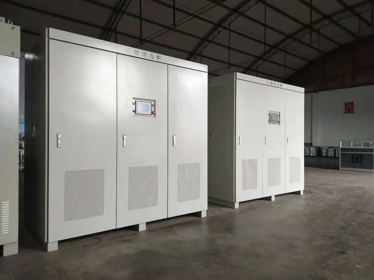
SINGAPORE SHIPYARD 400kVA 415V / 50Hz → 415V / 60Hz
INDONESIA SHIPYARD 2 × 1200kVA 380VAC / 50Hz → 380–480VAC / 60Hz
HIGH-VOLTAGE PORT PROJECT 5MVA 10kV / 50Hz → 6kV or 6.6kV marine power
Singapore 400 kVA containerized shore power frequency converter
SINGAPORE · SHIPYARD PROJECT 400kVA Containerized Shore Power Frequency Converter
01
CONTAINERIZED FREQUENCY CONVERTER

Singapore 400kVA Containerized Frequency Converter

A 400kVA outdoor containerized shore power system was supplied for a shipyard project in Singapore. The system was configured for 415V / 50Hz input and 415V / 60Hz output.

The electrical equipment was installed, internally wired and tested in the container before shipment.

CAPACITY 400kVA
INPUT 415V / 50Hz
OUTPUT 415V / 60Hz
INSTALLATION Outdoor Container
APPLICATION Shipyard
STATUS Operating
Delivered, commissioned, accepted and operating
02
DUAL LOW-VOLTAGE CONVERTERS

Indonesia 2 × 1200kVA Frequency Conversion Project

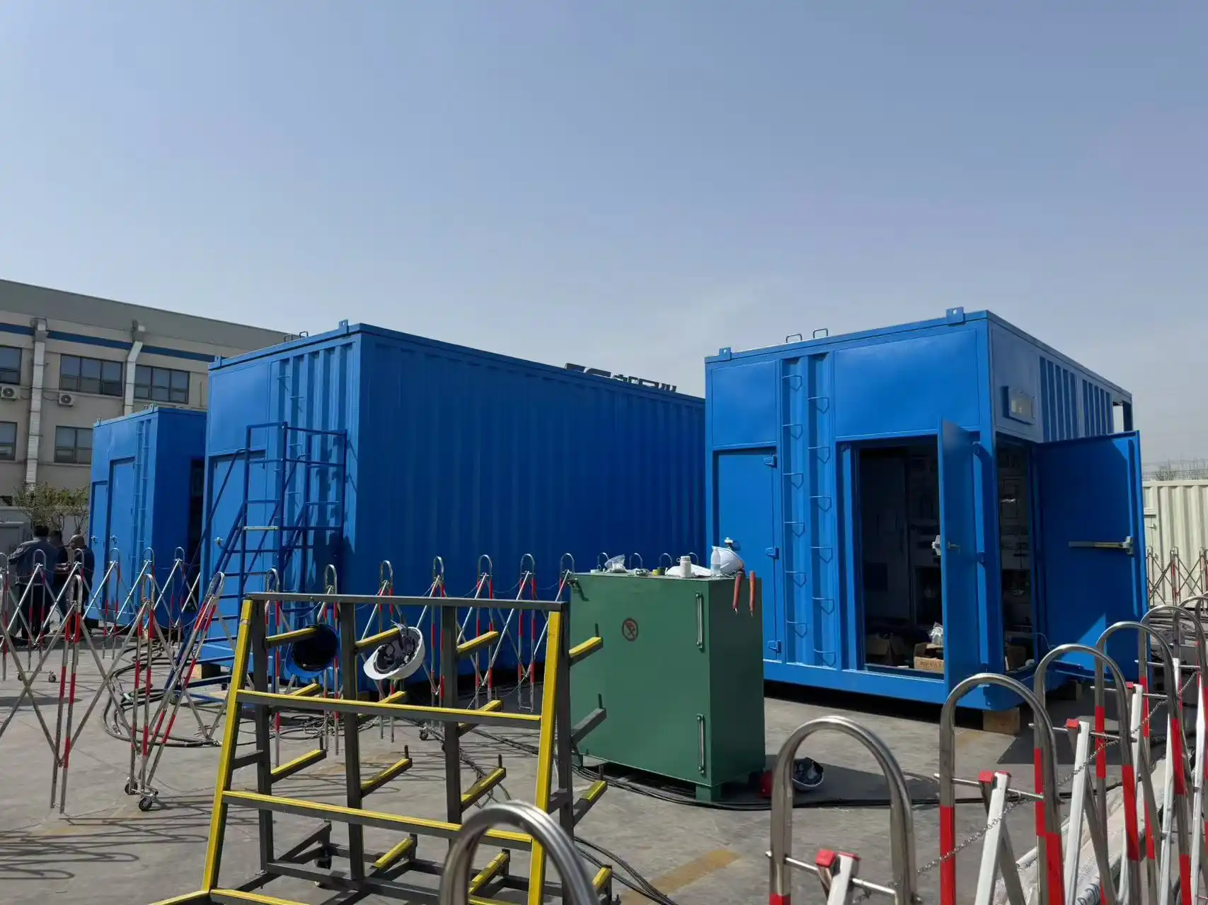
Two 1200kVA shore power frequency converters were supplied for a shipyard project in Indonesia.

The units accept 380VAC ±15% at 50Hz ±5% and provide an adjustable 380–480VAC output at 60Hz for different vessel voltage requirements.

CAPACITY 2 × 1200kVA
INPUT VOLTAGE 380VAC ±15%
INPUT FREQUENCY 50Hz ±5%
OUTPUT 380–480VAC / 60Hz
APPLICATION Shipyard
STATUS Operating
Delivered, commissioned, accepted and operating
Indonesia two 1200 kVA shore power frequency converters
INDONESIA · SHIPYARD PROJECT Two 1200kVA Shore Power Frequency Converters
5 MVA high-voltage shore power conversion system
HIGH-VOLTAGE PORT SHORE POWER 5MVA High-Voltage Shore Power Conversion System
03
MVA-CLASS HIGH-VOLTAGE SYSTEM

5MVA High-Voltage Shore Power Project

A 5MVA high-voltage shore power system was configured for a domestic port project.

The system converts 10kV / 50Hz industrial power into 6kV / 50Hz or 6.6kV / 60Hz marine power for high-voltage vessel connection.

CAPACITY 5MVA
INPUT 10kV / 50Hz
OUTPUT OPTION 1 6kV / 50Hz
OUTPUT OPTION 2 6.6kV / 60Hz
APPLICATION High-Voltage Port Shore Power
PROJECT-SPECIFIC CONFIGURATION Send your required capacity, input voltage, output voltage, frequency and application to discuss a similar shore power configuration.
Discuss a Similar Configuration
FAQ & TECHNICAL RFQ

Marine Frequency Converter FAQ

Review common questions about marine frequency conversion, voltage matching, capacity selection, installation, communication and factory testing.

FREQUENCY CONVERSION 50Hz ↔ 60Hz

Match different shore-grid and vessel operating frequencies.

OUTPUT CONFIGURATION Voltage and Phase Matching

Configure the required vessel voltage and phase sequence.

CAPACITY SELECTION Load-Based Engineering

Review rated load, current, motor starting and operation.

FACTORY VERIFICATION Project-Specific FAT

Define inspection, electrical testing and acceptance scope.

01 What is a marine frequency converter?

A marine frequency converter is a static power-conversion device that receives an available AC supply and delivers the voltage, frequency and phase sequence required by a vessel electrical system.

02 Where is a marine frequency converter used?

It can be used in ports, shipyards, dry docks, vessel maintenance facilities and electrical testing applications where the available grid does not match the vessel power system.

03 Can it convert 50Hz shore power to 60Hz vessel power?

Yes. A 50Hz-to-60Hz marine frequency converter is commonly used when the port or shipyard grid operates at 50Hz and the vessel distribution system requires 60Hz power.

04 Can it convert 60Hz shore power to 50Hz vessel power?

Yes. Reverse-frequency conversion can be configured when the available shore-side supply is 60Hz and the vessel requires 50Hz power.

05 Can one system change both voltage and frequency?

Yes. Frequency conversion is completed by the converter, while voltage matching can be achieved through converter output control, transformer configuration or a coordinated combination of both.

06 Can the output phase sequence be adjusted?

Yes. Output phase sequence can be adjusted through the control system for vessel connection and commissioning.

07 How is marine frequency converter capacity selected?

Initial capacity selection considers total rated load, rated voltage, rated current, peak or inrush current, the largest motor, starting method and simultaneous operating loads.

08 What is different about low-voltage and high-voltage configurations?

Low-voltage configurations generally use an IGBT static frequency-conversion cabinet. High-voltage configurations are engineered as coordinated multi-cabinet systems with project-configured transformers, switchgear, converter power units, protection and auxiliary equipment.

09 Can SDACME supply only the frequency converter?

Yes. The converter can be supplied as core equipment, or transformers, switchgear, monitoring, protection, shore connection equipment and container integration can be included according to the required scope.

10 Are indoor, outdoor and containerized versions available?

Yes. Indoor cabinets, outdoor enclosures and containerized installations are available according to the site environment, cooling requirements and selected equipment scope.

11 What communication interfaces are available?

Available interfaces include RS232, RS485, CAN and Profibus, with integration into PLC, HMI or SCADA systems.

12 What tests are completed before shipment?

Factory testing can include visual and wiring inspection, insulation and withstand-voltage testing, output voltage, voltage regulation, frequency, dynamic response, protection, efficiency, noise, HMI and communication checks.

TECHNICAL CONFIGURATION & QUOTATION

Send Your Marine Frequency Converter Requirements

Submit the available shore-side and vessel electrical data to receive a suitable technical configuration and quotation.

START WITH THE CORE ELECTRICAL DATA Input voltage and frequency, required vessel output, estimated capacity and main load information are enough for an initial technical review.
01 Submit Electrical Data
02 Technical Review
03 Configuration & Quotation
TECHNICAL RFQ CHECKLIST

Information for Initial Converter Selection

9 ITEMS
01
Contact Information

Contact name, company, country, email and complete business contact details.

02
Shore-Side Input

Input voltage, input frequency and available grid capacity.

03
Grid Conditions

Earthing method and short-circuit capacity when available.

04
Required Vessel Output

Output voltage, output frequency and required capacity.

05
Operating Load

Continuous load, peak load and power factor.

06
Motor Starting Conditions

Largest motor, starting method, starting current and operating sequence.

07
Installation Form

Indoor, outdoor or containerized installation requirements.

08
Required Equipment Scope

Converter, transformer, switchgear, monitoring, connection equipment, container integration, commissioning or training.

09
Available Technical Files

Load list, single-line diagram, vessel electrical data or technical specification.

Complete project information supports a faster review of converter capacity, voltage matching, equipment scope and factory test requirements.

Technical Inquiry & Request Form
Tell us about your application and technical requirements. Our engineering team will review your request and provide a suitable configuration and quotation.
Please enter your complete WhatsApp number, including the country code, so our engineer can contact you directly.