
Electrical acceptance of a shore power system has to prove more than one thing.
An insulation test verifies whether a defined part of the electrical system has acceptable insulation condition or dielectric strength. A protection test verifies whether an abnormal electrical condition is detected and whether the required trip or control action follows.
Neither result should be treated in isolation.
A shore power system should not be accepted simply because an insulation-resistance value looks high, a withstand-test sheet says “pass,” or a protection relay responds to a secondary-injection signal. The test boundary, measurement path, approved settings, trip circuit, breaker action and final records all have to represent the equipment that will actually enter service.
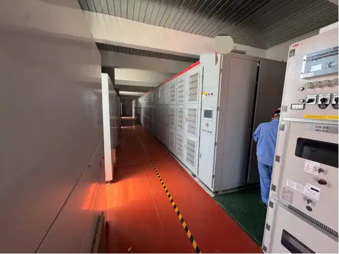
Electrical Acceptance Is a Sequence, Not a Single Test
A shore power package can combine switchgear, transformers, frequency-conversion equipment, busbars, cables, CTs, VTs, protection relays, auxiliary supplies, interlocks and supervisory controls.
Testing these components individually is necessary, but it does not automatically prove that the complete system is ready for energization.
A practical acceptance sequence moves through several layers:
- Equipment and parameter verification
- Wiring and secondary-circuit inspection
- Insulation-condition verification
- Applicable dielectric withstand testing
- CT/VT and measurement-path verification
- Protection-relay functional testing
- Trip-path and breaker-operation verification
- Interlock, alarm and feedback verification
- Integrated operating checks
- Acceptance-record review and closeout
Acceptance evidence builds layer by layer
This sequence reflects an important engineering distinction. A relay test assumes that the signal reaching the relay is meaningful. A breaker trip test assumes that the protection output reaches the trip circuit. A withstand test assumes that the intended electrical boundary has been created correctly.
Each layer depends on evidence established by the layers around it.
Define the Test Boundary Before Applying Voltage
A complete shore power installation can contain medium-voltage or low-voltage switchgear, transformers, frequency converters, busbars, cables, metering circuits, protection relays, surge-protection equipment, auxiliary supplies and control electronics.
These components do not automatically belong inside the same dielectric test boundary.
Before an insulation or withstand test begins, identify exactly which conductors and equipment are included. The review should use the final single-line diagram, wiring drawings, equipment voltage classes, applicable standards, manufacturer instructions and the actual connection state.
This becomes particularly important around power electronics and measurement circuits. A test suitable for a switchgear main circuit may not be suitable for a voltage transformer, surge protective device, converter power section or sensitive control circuit.

One shore power test procedure, for example, required deliberate treatment of voltage-transformer circuits, surge arresters, incoming and outgoing cables and transformer connections before withstand testing.
The engineering lesson is more important than any project-specific voltage value: a withstand voltage is meaningful only after the test object has been defined.
For the wider equipment verification sequence, see our shore power manufacturing and FAT guidance.
What Each Electrical Test Can—and Cannot—Prove
An acceptance programme becomes much clearer when each test is defined by its evidence boundary.
| Test or verification | What it can prove | What it does not prove by itself |
|---|---|---|
| Insulation resistance | Condition of insulation within the measured boundary | Dielectric withstand under an elevated AC test |
| Power-frequency withstand | Dielectric capability of the approved test boundary | Condition of every device excluded from that boundary |
| CT/VT verification | Ratio, polarity, wiring and measurement-path correctness | Relay timing or breaker trip performance |
| Secondary injection | Relay pickup, timing, logic and outputs | Complete primary measurement and downstream trip chain |
| Breaker functional trip | Trip circuit and breaker response | Correct relay settings or CT polarity |
| Feedback verification | Correct position and status indication | Mechanical condition under every possible fault scenario |
| FAT integrated test | Factory baseline of assembled equipment | Site interfaces added after transportation and installation |
| SAT verification | Installed condition and changed interfaces | Every factory test necessarily needs to be repeated |
This distinction prevents a common acceptance mistake: using evidence from one test to make a conclusion that belongs to another test.
Insulation Resistance Shows Condition, Not Full Withstand Capability
Insulation resistance and dielectric withstand are related, but they answer different engineering questions.
An insulation-resistance test applies a defined DC test voltage and measures resistance between selected conductors and earth or between circuits.
It can help identify abnormal condition associated with:
- Moisture
- Contamination
- Damaged insulation
- Incorrect installation
- Unintended electrical connection
But a high resistance value does not automatically demonstrate that the equipment has passed the required power-frequency withstand test.
The measurement record should identify the circuit tested, the test boundary, test voltage, equipment condition and result. Comparing results only makes sense when the test conditions are understood.
Power-Frequency Withstand Testing Requires a Controlled Boundary
A power-frequency withstand test applies an elevated AC voltage to a defined circuit for the required duration to demonstrate dielectric strength.
The applicable test condition depends on:
- Equipment voltage class
- Equipment type
- Applicable standard
- Insulation system
- Previous equipment testing
- Project specification
- Factory or installed test condition
Transformer insulation tests, switchgear tests and assembled-system tests can therefore have different boundaries and requirements.
Sensitive Components Can Change the Entire Test Plan
A stricter electrical test is not automatically a better test.
Power semiconductor circuits, voltage transformers, surge-protection devices, measurement networks and communication electronics do not necessarily share the same withstand capability as the main power circuit.
When the boundary is too broad
Sensitive equipment can remain connected and be exposed to an inappropriate test condition.
When the boundary is too narrow
Part of the actual insulation system that should have been verified can be accidentally excluded.
Before testing, review:
- Main power circuit
- Measurement circuits
- Protection inputs
- Auxiliary power
- SPDs or surge arresters
- PT/VT connections
- Converter interfaces
- External cables
- Earthing arrangements
- Manufacturer-required disconnections
Protection Verification Starts Before the Relay Test
Protection testing should not begin by assuming that the relay input is already correct.
Before relay behaviour can be trusted, the measurement path should be verified.
This includes:
- CT identification
- CT ratio
- CT polarity
- Secondary wiring
- VT identification and ratio
- VT polarity where relevant
- Secondary grounding
- Terminal assignment
- Scaling in the relay or control system
A project-specific shore power test procedure illustrates this sequence clearly: current measurement channels were checked using controlled simulated quantities before protection behaviour was verified.
Why CT and VT Errors Matter So Much
Current transformers and voltage transformers connect the physical power system to protection, metering and control. Errors in this interface can create faults that are difficult to recognize because the protection relay itself may remain completely healthy.
Incorrect CT ratio
The relay receives a correctly shaped signal at the wrong magnitude.
Reversed CT polarity
Directional or power-based protection can interpret power flow incorrectly.
Wrong phase assignment
The relay can associate an electrical condition with the wrong phase.
VT scaling error
Voltage, power or directional calculations can become incorrect.
Incorrect secondary grounding
The measurement circuit may no longer behave as designed.
Use Secondary Injection to Verify Relay Behaviour
Secondary injection supplies controlled quantities directly to the protection device.
It is useful because engineers can test protection behaviour without creating an actual high-energy primary fault.
Depending on the function under test, secondary injection can verify:
- Pickup threshold
- Timing
- Inverse-time behaviour
- Instantaneous operation
- Voltage protection
- Frequency protection
- Output contacts
- Indications
- Alarms
- Internal logic
One project test procedure used a protection test instrument to inject secondary current and verify inverse-time and instantaneous protection behaviour.
The important evidence is not the project-specific current multiple. It is the verification method: known input → expected response → measured response → recorded result.
For the wider relationship between protection functions and interlock logic, see our shore power protection and interlock functions guide.
Relay PASS Does Not Mean Protection System PASS
A relay can operate correctly while the actual system fails to reach the required safe state.
A successful relay response does not automatically prove the CT/VT path, trip wiring, auxiliary supply, breaker operation, feedback or event recording.
A simplified protection path may be represented as:
Possible hidden failures include:
- Loose or incorrect wiring
- Missing auxiliary trip supply
- Defective intermediate relay
- Open trip circuit
- Failed breaker trip coil
- Breaker mechanical failure
- Incorrect auxiliary-contact feedback
- Missing alarm or event record
Prove the Complete Trip Path
Where practical, a functional protection test should follow the chain far enough to demonstrate the intended system response.
- Initiating measurement or simulation
- Relay detection
- Output contact operation
- Intermediate logic
- Trip-power availability
- Breaker trip-coil operation
- Actual breaker opening
- Open-position feedback
- Alarm indication
- Event or first-out record
If a part of the chain is simulated rather than physically tested, the simulation boundary should be identified in the test record.
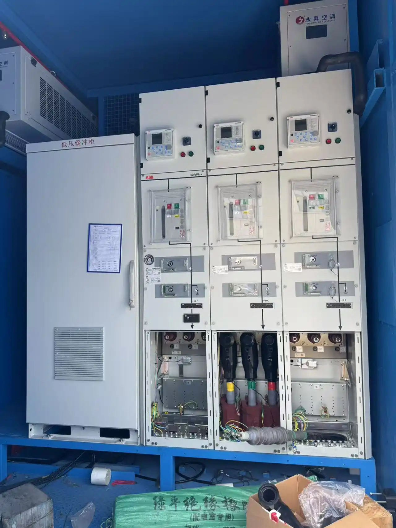
The equipment functions behind these actions are discussed further in our shore power input and output switchgear guide.
Test the Action and the Evidence of the Action
A protection event creates two outputs: the physical response and the record of what happened.
If a breaker opens correctly but the control system reports the wrong initiating condition, the immediate electrical hazard may be removed while future diagnosis becomes unreliable.
If the breaker opens but open-position feedback remains false, the control system may not recognize that the intended safe state has been reached.
Where applicable, verify:
- Physical action
- Position feedback
- Alarm text
- Event timestamp
- First-out information
- Reset behaviour
Protection Settings Are Part of the Acceptance Evidence
A relay can pass every functional test and still be configured incorrectly for the project.
Protection settings should come from an approved protection or coordination basis. They should not be copied from technician habit, another berth, another vessel, a similarly rated converter or an outdated settings file.
A controlled test record can include:
- Relay model and device identification
- Firmware revision
- Settings revision
- CT/VT ratios
- Enabled functions
- Pickup and timing settings
- Test-set identification
- Calibration status
- Expected result
- Measured result
- Final loaded configuration
A result is only valid for the configuration that was actually tested.
A Good Test Report Records More Than PASS
A future engineer should be able to understand the acceptance decision after the original test team has left.
The record should make it possible to reconstruct:
- What was tested
- What was connected and disconnected
- What instrument was used
- What configuration was active
- What result was expected
- What result was observed
- Whether any deviation occurred
- How the deviation was resolved
- Which final revision was accepted
What to Do When a Test Does Not Match the Expected Result
Acceptance testing is not a process of repeatedly running the same test until a passing result appears.
A nonconforming result should trigger a controlled closeout process:
| Observation | Engineering meaning | Appropriate response |
|---|---|---|
| Insulation resistance is lower than the factory baseline | Boundary, contamination, moisture, termination or insulation condition may have changed | Confirm the boundary and investigate before energization |
| Relay pickup is outside expected tolerance | Settings, scaling, test connection or relay behaviour may be incorrect | Verify configuration and repeat the controlled test |
| Relay operates but breaker remains closed | The downstream trip path has not been proven | Inspect trip power, wiring, intermediate relay, trip coil and breaker |
| Breaker opens but feedback remains closed | The physical action works but the feedback chain does not | Verify auxiliary contacts, wiring and point mapping |
| CT polarity is reversed | Directional or power-related functions may be invalid | Correct wiring and repeat all affected tests |
| Settings file differs from the approved revision | Previous test evidence may no longer represent the final design | Resolve the revision and repeat affected functions |
| SAT boundary differs from FAT | Factory test evidence cannot be copied blindly | Define the correct installed test scope |
Acceptance Evidence Has Dependencies
One correction can invalidate more than one previous test result.
If CT wiring is changed
Measurement verification, relay tests, directional protection and affected power calculations may need to be repeated.
If protection settings are changed
Previously recorded pickup and timing tests may no longer represent the delivered configuration.
If a trip circuit is rewired
Breaker functional tests, feedback and alarm verification should be reconsidered.
If a cable termination is repaired
The insulation evidence for that affected circuit may need to be repeated.
FAT Establishes the Factory Baseline
Factory acceptance testing provides a controlled environment before the equipment is transported to site.
The factory stage can establish evidence for:
- Equipment identity
- Wiring condition
- Insulation boundary
- Applicable dielectric tests
- CT/VT circuits
- Protection-relay functions
- Internal trip circuits
- Breaker operation
- Interlocks and alarms
- Control logic
- Settings revisions
- Recorded results
Loaded operating tests can then add another evidence layer by showing whether measurement, control and protection remain coherent during actual system operation.
Transport and Installation Create a New Electrical State
The equipment that arrives at site is not electrically identical to the factory test setup.
Between FAT and energization:
- Cabinets are transported
- Cables are installed
- Terminations are completed
- Switchgear sections may be reconnected
- Field CT/VT circuits are connected
- Auxiliary supplies change source
- Berth interfaces are added
- Communication links are commissioned
- External trip and interlock circuits are introduced
FAT evidence remains important, but it does not eliminate site verification.
SAT Should Target the Changed Boundary
The role of SAT is to identify what may have changed since the factory baseline.
Depending on the project, relevant site checks can include:
- Insulation condition
- Cable insulation
- Wiring continuity
- Termination condition
- Phase sequence
- CT/VT wiring
- Polarity
- Field trip circuits
- Breaker operation
- Remote feedback
- External interlocks
- Communication interfaces
- End-to-end protection operation
FAT → Installation → SAT Should Form One Evidence Chain
The strongest acceptance package links all stages instead of treating FAT and SAT as unrelated folders of test reports.
Final acceptance should confirm that factory evidence remains applicable, changed interfaces have been verified, anomalies are closed, settings are controlled and the test record represents the delivered equipment.
Loaded Operation Adds Another Verification Layer
After electrical integrity and protection functions have been checked, loaded operation can provide additional system-level evidence.
A project test programme can include progressive loading, full-load operation, overload behaviour, stability monitoring and periodic recording of electrical parameters.
These tests do not replace insulation or protection verification. They show whether measurement, protection and control remain coherent when the system operates.
Detailed harmonic and waveform analysis belongs to the dedicated shore power harmonic-testing article.
Common Shore Power Acceptance Errors
Applying one test voltage to the entire connected package
Different equipment can have different dielectric requirements and test boundaries.
Treating insulation resistance as a withstand test
A high resistance value does not replace dielectric verification.
Testing the relay before confirming its inputs
The relay can respond correctly to an incorrect CT/VT configuration.
Verifying relay output but not breaker action
Wiring, auxiliary supply or trip-coil failures can remain hidden.
Confirming breaker action but ignoring feedback
The physical state and reported state can disagree.
Using an unapproved protection-settings revision
The test can prove behaviour that does not correspond to the final design.
Repeating SAT tests without checking the installed boundary
Equipment added after FAT may change the applicable site test condition.
Recording only “PASS”
Future engineers cannot reconstruct the acceptance decision.
Fixing a problem without retesting dependent functions
One correction can invalidate several previous results.
Treating FAT and SAT as unrelated documents
The site team loses the baseline needed to understand what changed.
What Should a Traceable Acceptance Record Contain?
| Evidence item | What should be identifiable |
|---|---|
| Test object | Equipment, feeder or circuit |
| Test purpose | The engineering question the test answers |
| Electrical boundary | Connected, isolated and disconnected equipment |
| Applicable requirement | Standard, specification or approved procedure |
| Equipment condition | FAT, installed SAT state or maintenance condition |
| Instrument | Identification and calibration status |
| Measurement configuration | CT/VT ratios, wiring and scaling |
| Protection configuration | Settings revision and enabled functions |
| Applied quantity | Voltage, current, frequency or simulation |
| Expected result | Acceptance value, timing or required action |
| Actual result | Measured value or observed action |
| Trip-path result | Final controlled-device action |
| Feedback result | Breaker state, alarm and event record |
| Deviation | Abnormal observation or simulation boundary |
| Corrective action | What changed and why |
| Retest scope | Which evidence was repeated after correction |
| Final acceptance | Responsible approval and final status |
Information Needed Before Preparing the Test Schedule
- Final single-line diagram
- Primary wiring drawings
- Secondary wiring drawings
- Voltage classes
- Converter architecture
- Transformer specification
- Switchgear specification
- Cable and termination information
- Manufacturer test limitations
- Applicable equipment standards
- Approved withstand criteria
- Protection study
- Approved protection settings
- CT and VT ratios and polarity
- Breaker trip circuits
- Interlock cause-and-effect matrix
- External trip interfaces
- SCADA feedback requirements
- FAT and SAT responsibilities
- Witness points
- Test-equipment and calibration requirements
- Final acceptance-record format
These inputs determine not only which tests should be performed, but also which results remain valid when the system configuration changes.
Frequently Asked Questions
Is an insulation-resistance test the same as a withstand test?
No. Insulation resistance evaluates insulation condition using a defined DC test voltage. A power-frequency withstand test demonstrates dielectric capability of a defined electrical boundary under an approved elevated AC voltage.
Can a protection relay be tested without primary fault current?
Yes. Secondary injection can verify pickup, timing, logic, outputs and indications by supplying controlled quantities directly to the protection device. It does not automatically verify the complete CT-to-breaker protection chain.
Does secondary injection prove the complete protection system?
No. Additional checks may be needed for CT/VT circuits, trip wiring, auxiliary power, breaker action, feedback and event recording.
Does a breaker opening prove the entire protection function?
Not necessarily. The breaker may operate correctly while measurement scaling, relay settings, feedback or alarm recording remain incorrect.
Should every FAT withstand test be repeated during SAT?
No. SAT should first determine what changed during transportation, cable installation, termination and site integration. Any site high-voltage test should follow the approved equipment and project procedure.
What happens if a relay setting changes after FAT?
Identify which previous results depend on that setting and repeat the affected protection tests so the final acceptance evidence represents the delivered configuration.
Why is recording the actual measured result important?
Because the result may later be needed to compare against a factory baseline, investigate degradation or confirm exactly what was accepted. “PASS” alone does not preserve that engineering evidence.
Technical References
The applicable edition and project scope should always be confirmed before use.
- IEC/IEEE 80005-3:2025 — Low-voltage shore connection systems.
- IEC/IEEE 80005-1:2019+A1:2022+A2:2023 — High-voltage shore connection systems.
- IEC 60255-1:2022 — Measuring relays and protection equipment — Common requirements.
- IEC 60255-151:2009 — Functional requirements for over/under-current protection.
- IEC 60076-3:2013+A1:2018 — Power transformer insulation levels and dielectric tests.
- IEC 62271-200:2021+A1:2024 — AC metal-enclosed switchgear above 1 kV up to and including 52 kV.
Agree the Electrical Acceptance Boundary Before Testing Begins
A useful shore power test programme does not begin with a generic list of withstand voltages or relay-test multiples. It begins with the actual electrical architecture.
Send the single-line diagram, voltage classes, transformer and switchgear data, protection study, relay settings, CT/VT data, trip matrix, FAT/SAT responsibilities and required witness points.
SDACME can review these inputs as one acceptance system—connecting insulation boundaries, measurement paths, protection functions, trip verification, site changes and final acceptance records into a traceable engineering review.
Send Your Electrical Test Requirements