Shore Power System Architecture & Components
A complete shore power system is more than a frequency converter. It coordinates grid connection, voltage transformation, frequency conversion, switchgear, protection, control, cable management and the vessel interface as one integrated electrical system.
There Is No Single Fixed Shore Power Architecture
A shore power system should be engineered around the electrical conditions of both the shore and the vessel. Equipment arrangement, voltage transformation, frequency conversion, protection, connection and control requirements can therefore differ substantially between projects.
Shore-Side Conditions
- Grid voltage
- Grid frequency
- Available power capacity
- Earthing arrangement
- Short-circuit level
- Existing distribution system
Vessel-Side Conditions
- Required connection voltage
- Required frequency
- Continuous operating load
- Peak demand
- Largest starting load
- Vessel connection interface
Project Conditions
- Number of berths
- Simultaneous vessel operation
- Cable route and distance
- Indoor or outdoor installation
- Environmental conditions
- Required supply scope
From the Port Grid to the Vessel
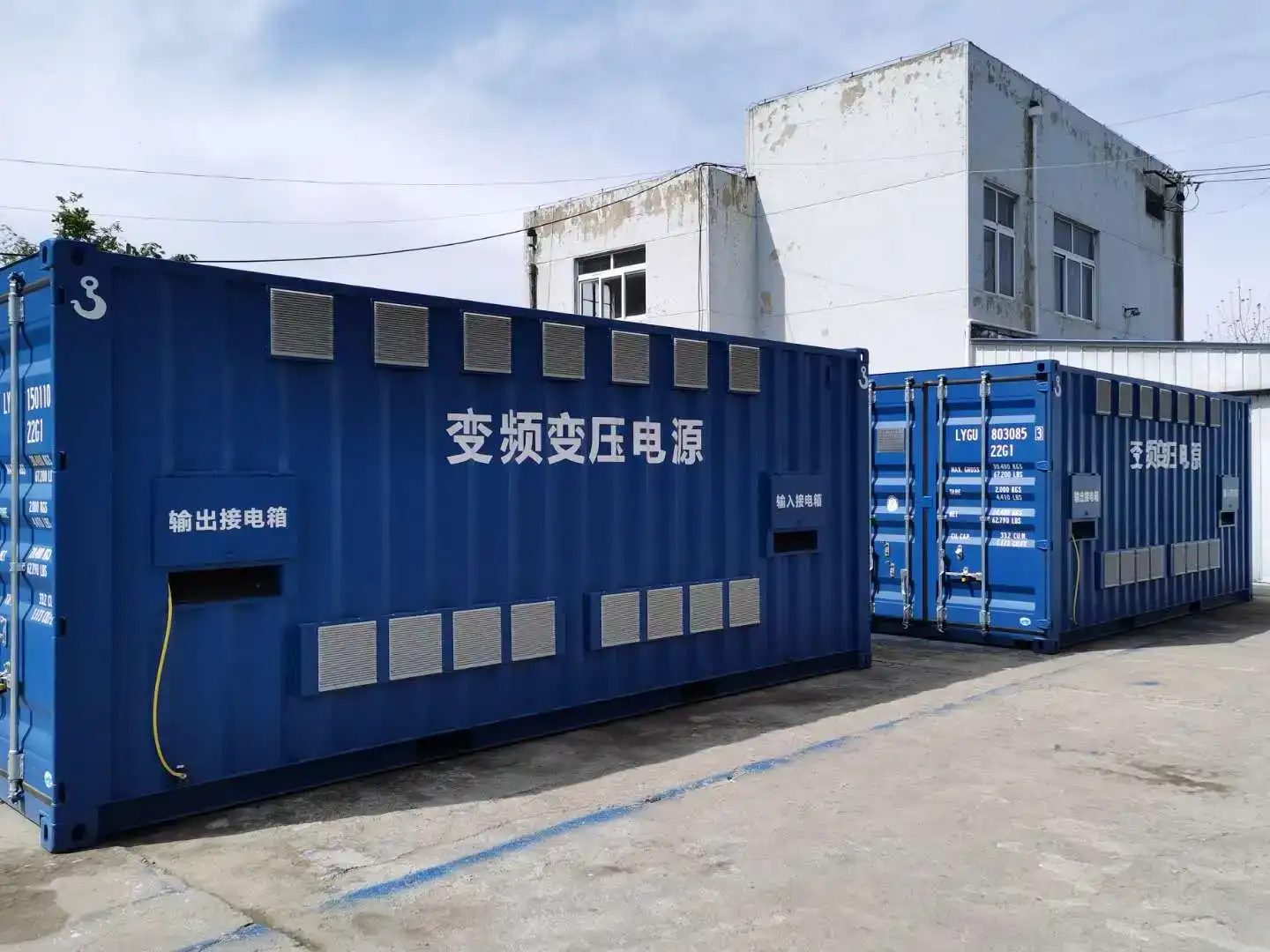
A complete shore power architecture coordinates power conversion, transformation, protection, control and the physical shore-to-vessel interface. The exact sequence depends on the project.
Port / Utility Grid
Incoming electrical supply and available port distribution capacity.
Incoming Switchgear
Switching, isolation, protection and electrical metering.
Input Transformer
Voltage adaptation or phase-shifting where required.
Where RequiredFrequency Converter
Matches grid frequency to vessel frequency where conversion is required.
ConditionalOutput Transformer
Voltage matching, isolation or grounding-related system functions.
Where RequiredOutput Switchgear
Feeder protection, isolation, distribution and grounding coordination.
Connection & Cable Interface
Connection box, cables and cable-management arrangement.
Vessel Receiving System
Ship-side receiving equipment and vessel main electrical distribution.
Control & Monitoring Layer
Not every shore power project requires every component shown above. Final equipment selection is based on grid conditions, vessel electrical requirements and the approved project architecture.
How Conversion and Transformation Fit Into the Power Chain
Frequency and voltage are separate design requirements. Depending on the shore grid and vessel electrical system, a project may require frequency conversion, voltage transformation, both functions or neither.
Shore Power Frequency Converter
Matches the shore supply frequency to the vessel requirement where the two systems operate at different frequencies, such as 50 Hz to 60 Hz or 60 Hz to 50 Hz.
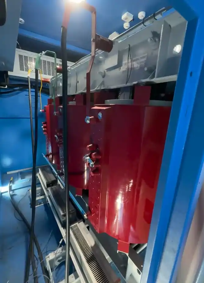
Input / Phase-Shifting Transformer
May support incoming voltage adaptation, converter input requirements, isolation or phase-shifting functions associated with the selected conversion topology.
Isolation / Voltage-Matching Transformer
May provide step-up or step-down transformation, electrical isolation and support for the required grounding arrangement.
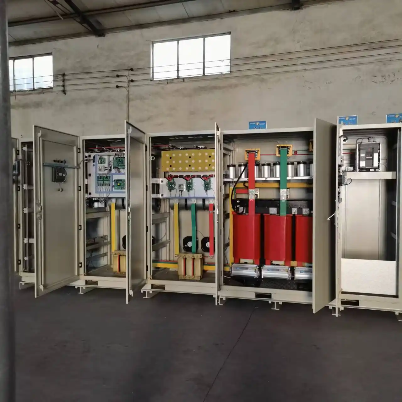
The final transformer and converter arrangement depends on grid voltage, vessel voltage, frequency requirements, grounding and the approved project configuration.
Switching, Protection and Grounding Must Work as One System
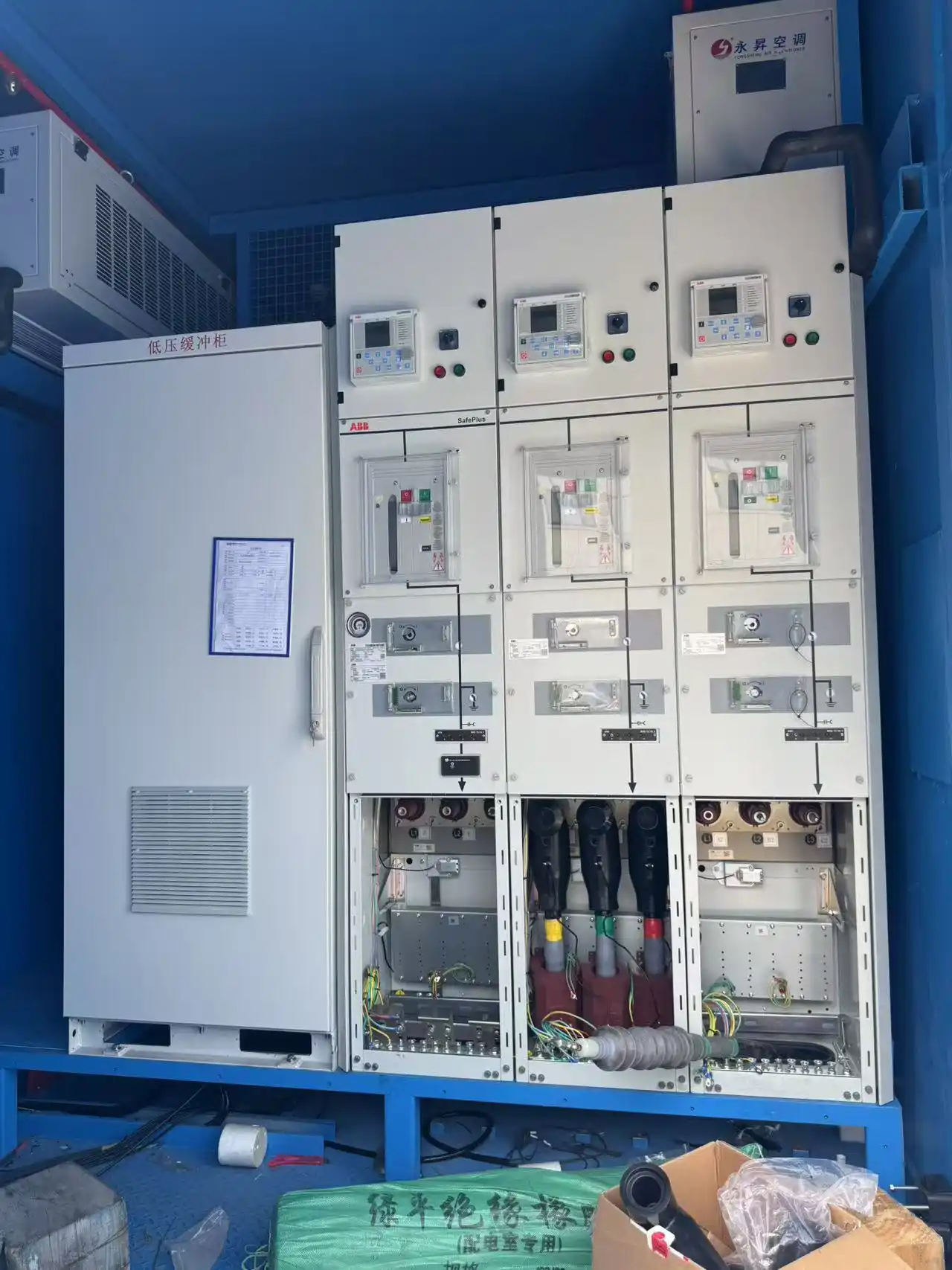
Shore power switchgear provides more than electrical switching. It forms part of a coordinated architecture involving isolation, protection, metering, feeder control, grounding and the vessel electrical system.
Incoming switchgear can provide isolation, switching, metering and feeder protection. Output switchgear can provide vessel feeder control, distribution, protection and coordination with connection interlocks.
Depending on the approved electrical design, protection may include:
- Overcurrent protection
- Overvoltage and undervoltage protection
- Frequency and phase-related protection
- Differential protection where required
- Interlocking and emergency shutdown functions
Grounding and neutral-grounding equipment must be coordinated with transformer configuration, the vessel system, fault-current limits and the overall protection philosophy.
Switching
Isolation, feeder control and operating sequence.
Protection
Coordinated fault detection and protective functions.
Grounding
Earthing and neutral treatment based on system design.
The Power Layer and Control Layer Work Together
Main electrical equipment transfers power, while the control and information layer coordinates operating status, permissions, alarms, measurements and project-specific communication.
Local Control
PLC and HMI coordinate system operation and provide local status information.
Monitoring
Metering, alarms and event information support supervision and troubleshooting.
Communication
SCADA and ship–shore interfaces can be configured according to project requirements.
Shore Power Connection Box
A shore power connection box provides a defined electrical interface between the shore-side system and the cables connecting the vessel.
- Main power connection
- Earthing connection
- Auxiliary or control connections
- Status or interlock interfaces where required
- Interface with the selected cable-management arrangement
Its configuration depends on voltage class, current, vessel interface, berth layout and the required operating method.
Shore Power Cable Management
The electrical system does not end at the output switchgear. Power, control and earthing conductors still need to be transferred and supported safely between the berth and vessel.
Manage cable movement between shore and vessel.
Support cable weight and operating position.
Manage the required connection path and distance.
Reduce unnecessary mechanical stress on cables.
How Shore Power Architecture Changes by Project
Architecture changes when the electrical and operating conditions change.
Same Frequency
Frequency conversion may not be required when shore and vessel frequency already match.
Different Frequency
A converter becomes part of the power chain where grid and vessel frequencies differ.
Different Voltage
Voltage transformation may still be required even when frequency already matches.
Low Voltage vs High Voltage
LV and HV shore connections create different requirements for current, protection, grounding and connection equipment.
Single Berth vs Multi-Berth
Multi-berth systems require review of simultaneous demand, independent feeders, connection locations and future expansion.
Start with the shore grid, vessel voltage, frequency, load and berth arrangement.

Site Conditions Can Change the Physical Architecture
Shore power equipment operates as part of a marine electrical installation. Temperature, humidity, salt, dust, altitude and maintenance access can affect cooling, insulation, enclosure requirements and equipment arrangement.

Shore Power System Architecture FAQs
Direct answers to common engineering questions about shore power system components and architecture.
What are the main components of a shore power system?
Is a frequency converter always required?
When is a transformer required in a shore power system?
What does shore power switchgear do?
What is a shore power connection box?
What does a shore power cable management system do?
How do PLC, HMI and SCADA work in a shore power system?
Why are grounding and protection part of the system architecture?
Can one shore power system supply multiple berths?
How do environmental conditions affect shore power architecture?
Send Your Shore Power System Requirements
The most effective way to define a shore power architecture is to begin with the actual shore grid, vessel electrical requirements, berth arrangement and required supply scope.
Request a Shore Power System Configuration →