Magnetron Sputtering Systems for Research and Thin Film Deposition
Select a magnetron sputtering system around your target material, substrate size, temperature limit, film structure and throughput requirements. SDACME provides DM-series sputtering equipment for research and process development, with project configurations evaluated for DC/RF power selection, target arrangement, substrate handling and deposition requirements.
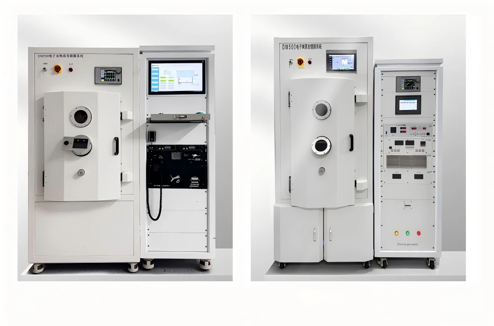
Start with the Film, Substrate and Process — Then Select the Sputtering System
A magnetron sputtering system should not be selected only by chamber size or model number. The practical selection path starts with the target material, required film structure, substrate size, temperature limit and expected throughput. These inputs determine which sputtering process, target arrangement, substrate configuration and system scale should be evaluated.
A research user depositing one conductive metal, a team developing dielectric multilayers and a pilot process working with several target materials can require very different sputtering deposition system configurations. Start from the deposition task first, then define the hardware.
Select the Power Route from the Material
The target material is the first process input. Conductive targets commonly lead to DC magnetron sputtering, while insulating or dielectric materials may require RF sputtering. Compound-film formation may also introduce a reactive deposition route.
Define Layers, Materials and Target Count
A single-material film, multilayer stack and co-sputtering task require different target arrangements. The film structure determines whether the system should be evaluated around one cathode, several targets, sequential deposition or simultaneous deposition.
Match the Equipment to the Substrate
Substrate dimensions, shape and thermal limits influence the chamber, fixture and source geometry. Depending on the project, substrate rotation, heating, cooling, bias or dedicated fixtures can be evaluated around the actual deposition requirement.
Research, Pilot or Production?
A laboratory or research sputtering system is generally selected around process flexibility and sample development. Pilot and production requirements place more emphasis on batch quantity, repeatability, loading workflow, throughput and operating efficiency.
Once the target material and film route are clear, the next decision is whether the process should use DC, RF, reactive or multi-target sputtering.
Continue to Sputtering Process Selection →Choose DC, RF, Reactive or Multi-Target Sputtering Around the Film You Need
The right sputtering route depends first on the target material and required film, then on whether the process needs one material, multiple sequential layers or simultaneous deposition. A DC sputtering system, RF sputtering system, reactive sputtering process and multi-target configuration solve different deposition tasks and should not be selected only by equipment size.
DC Magnetron Sputtering
A DC magnetron sputtering system is commonly considered when the target material is electrically conductive. It is widely associated with metal-film deposition and other processes where a stable DC discharge is appropriate for the selected target and process condition.
RF Magnetron Sputtering
An RF magnetron sputtering system is commonly evaluated for insulating or dielectric target materials where conventional DC operation is not suitable. The RF route should be selected together with the target material, desired film and process requirements rather than treated as a universal upgrade from DC.
Reactive Magnetron Sputtering
A reactive sputtering system introduces a reactive gas into the deposition environment so that the deposited film can form a compound with the sputtered material. This changes the process-selection task because gas control, target behavior and film requirements must be considered together.
Multi-Target & Co-Sputtering
A multi-target sputtering system can support processes that require more than one target material. Depending on the film objective, targets may be used sequentially for multilayer deposition or evaluated for simultaneous co-sputtering and co-deposition.
Quick Process Selection Reference
Use this as an initial route only. Final power and chamber configuration should follow the actual material and film requirement.
| Deposition Task | Common Starting Route | What to Confirm |
|---|---|---|
| Conductive metal target | DC magnetron sputtering | Target material, film specification, substrate and required deposition conditions |
| Insulating or dielectric target | RF magnetron sputtering | Target electrical properties, film requirement and compatible RF configuration |
| Compound film using reactive gas | Reactive sputtering | Target, reactive gas, required compound film and process-control requirement |
| Multilayer or several target materials | Multi-target sputtering | Number of materials, deposition sequence, changeover and contamination requirements |
| Simultaneous deposition from multiple materials | Co-sputtering / co-deposition | Material combination, composition objective, source arrangement and process-control requirement |
After the sputtering route is identified, the next decision is the system architecture: chamber arrangement, number of targets, substrate handling, vacuum configuration and the level of process integration.
Review System Configuration →Configure the Chamber, Targets, Substrate Handling, Vacuum and Integration Around the Process
Once the sputtering process is defined, the next step is to configure the magnetron sputtering equipment around the actual substrate, film structure and operating task. Chamber geometry, target quantity, substrate handling, vacuum architecture and automation requirements work together. Changing one of these factors can affect several other parts of the system.
Size the Chamber Around the Process Space
Chamber selection is not only a question of external equipment size. The internal process space must accommodate the substrate, target arrangement, source-to-substrate geometry, fixtures and required motion. Larger or more complex film structures can therefore require a different chamber architecture even when the substrate itself is relatively small.
Match Target Quantity to the Film Structure
A single-material process and a multi-layer or co-sputtering process need different cathode layouts. The target arrangement should be evaluated around material count, deposition sequence, simultaneous deposition needs and contamination control. Adding more targets is useful only when it supports the actual film-development task.
Configure Fixtures, Motion and Thermal Conditions
Substrate size, shape and thermal budget influence the fixture and handling design. Depending on the process, the system may need evaluation for rotation, heating, cooling, biasing, masks or dedicated sample fixtures. These functions should follow the film requirement rather than being added as generic options.
Main Chamber, Load-Lock or More Isolated Handling?
The vacuum architecture should match the required process environment and operating workflow. A conventional main-chamber arrangement may be sufficient for many research tasks, while applications that need reduced chamber exposure, faster sample exchange or more controlled transfer may require evaluation of a load-lock sputtering system or a more complex vacuum configuration.
Define How the System Will Be Operated and Integrated
Research equipment, shared laboratory platforms and pilot systems can require different levels of operation and integration. The project can be evaluated around the required level of operator control, process sequencing, monitoring, data handling and external system interface.
The website describes the level of operation and integration that a project may require. Detailed control logic, interlock thresholds, I/O allocation, register maps and internal sequencing belong to project-level engineering documentation rather than the public product page.
Once the system architecture is clear, the next question is whether the equipment fits the material and application task: metals, oxides, ceramics, conductive films, optical films and other thin-film development work.
Review Materials & Applications →Match the Target Material and Film Task to the Right Sputtering Configuration
Material name alone does not define a complete sputtering system. The same material can require a different process route depending on target form, film composition, substrate, temperature limit, layer structure and the intended function of the thin film. Material and application requirements therefore need to be reviewed together before the equipment configuration is fixed.
Metal Thin Films
Conductive metal targets are common starting points for DC magnetron sputtering. Projects involving aluminum, copper, gold, silver, titanium, molybdenum, tantalum or niobium thin films should still be evaluated against the required thickness, substrate, layer structure and film-performance target.
Oxide, Nitride and Dielectric Thin Films
Oxide, nitride and dielectric deposition can introduce different power and process-control requirements. Depending on the target and film route, RF sputtering or reactive sputtering may need to be evaluated for materials such as SiO2, AlN, Si3N4, TiN and other oxide or nitride films.
Transparent Conductive and Semiconductor-Related Films
Thin-film research involving ITO, ZnO, transparent conductive oxides, compound-semiconductor materials or perovskite-related films can require tighter consideration of material route, substrate condition and process repeatability. These applications should be reviewed as project-specific deposition tasks rather than treated as one universal sputtering configuration.
Magnetic, Energy and Emerging Thin-Film Research
Research requests can also involve magnetic or ferromagnetic films, MoS2, superconducting materials and battery-electrode thin films. For these applications, the material keyword alone is not enough to define the system. The project should be reviewed around the full film stack, substrate, contamination sensitivity and experimental objective.
From Material Request to System Requirement
Material keywords are useful starting points, but the equipment specification should be created from the complete deposition task.
| Material / Film Task | Typical Question | What Changes the System Selection |
|---|---|---|
| Metal thin films | Which conductive target and layer structure are required? | DC power route, target quantity, substrate size, film thickness and multilayer requirement |
| Oxide / nitride / dielectric films | Is the target insulating, or will the film be formed through a reactive process? | RF or reactive route, gas requirement, substrate thermal limit and process control |
| ITO / ZnO / TCO films | What electrical, optical or research objective defines the required film? | Material route, substrate condition, film uniformity requirement and repeatability |
| Multiple material films | Are materials deposited sequentially or simultaneously? | Target quantity, co-sputtering need, changeover and cross-contamination control |
| Battery / magnetic / emerging materials | Is the task material screening, process development or a defined device-film stack? | Research flexibility, chamber configuration, substrate handling and project-specific process needs |
Material and application tell us what the system needs to deposit. The next step is to turn those requirements into a practical selection: substrate size, temperature, number of materials, film structure, batch requirement and required flexibility.
Continue to the System Selection Guide →How to Choose a Magnetron Sputtering System
Choosing the right magnetron sputtering system means translating the film requirement into equipment requirements. Start with the target material and substrate, then define film structure, temperature limits, target quantity, system scale and the acceptance criteria that matter to your process.
Define the Target Material and Film
Identify the target material and the film you need to deposit. This determines whether the project should begin with DC, RF or reactive sputtering and whether special material or contamination requirements need to be considered.
Define Substrate Size and Thermal Limit
Substrate dimensions affect chamber space, fixture design and source geometry. For temperature-sensitive substrates, also define the maximum allowable substrate temperature before heating, cooling or other thermal-management options are evaluated.
Determine How Many Targets You Need
A single target may be enough for one-material deposition, while multilayer development or co-sputtering may require several target positions. The decision depends on whether materials are deposited sequentially, simultaneously or frequently changed.
Specify Thickness and Uniformity Requirements
Film thickness and uniformity expectations influence system geometry, substrate motion and the way the final configuration is evaluated. Avoid using a general phrase such as “high uniformity” without defining how uniformity will be measured and accepted.
Decide Whether the Task Is Research, Pilot or Production
A laboratory magnetron sputtering system is usually selected for flexibility and process development. Pilot and production systems place more weight on loading workflow, repeatability, batch quantity, operating efficiency and future process stability.
Confirm Installation and Operating Requirements
Site conditions and workflow can affect the final equipment layout. Before quotation, identify available installation space, utility conditions, preferred loading method and the level of operation or automation expected from the system.
Research, Pilot and Production Have Different Priorities
The terms laboratory, R&D, pilot and production describe how the equipment will be used. They should guide the configuration rather than act as rigid equipment categories.
Flexible Material and Process Development
A research sputtering system is typically evaluated around flexibility, small-batch work and the ability to develop or compare thin-film processes.
- Small samples or laboratory substrates
- Frequent material or process development
- Flexible target and substrate configuration
- Universities, institutes and R&D teams
Bridge Research to Repeatable Operation
A pilot magnetron sputtering system may need to retain process flexibility while introducing more repeatable loading, operation and batch handling.
- Process transfer from research
- Larger or repeated sample batches
- More defined operating sequences
- Evaluation before production scale-up
Throughput, Repeatability and Workflow
Production-oriented requirements place greater emphasis on the complete operating task, including repeatability, batch size, equipment workflow and integration.
- Defined batch and throughput targets
- Repeatable equipment operation
- Loading and process workflow
- Project-specific automation requirements
What Each Requirement Changes in the System
Use these inputs to convert a film-development task into a practical equipment specification.
| Requirement | Why It Matters | Main System Decision |
|---|---|---|
| Target material | Determines the starting sputtering route | DC / RF / reactive process and power configuration |
| Substrate size & shape | Defines process space and fixture requirements | Chamber, holder and source geometry |
| Temperature limit | Determines allowable thermal conditions | Heating, cooling and substrate-management strategy |
| Number of materials | Defines the required deposition sequence | Single target, multi-target or co-sputtering layout |
| Thickness & uniformity | Defines the film acceptance objective | Geometry, motion and project verification criteria |
| Research / pilot / production | Defines usage frequency and operating workflow | System scale, loading and automation level |
| Batch / throughput | Defines how the system will be used operationally | Chamber scale, handling and workflow configuration |
Prepare These Inputs for Faster System Selection
Once these requirements are defined, you can compare the DM200-250, DM300, DM400, DM500 and DM700 as equipment platforms instead of choosing only by model number or external size.
Compare Available DM Models →Compare the Available DM-Series System Platforms
SDACME currently presents five DM-series magnetron sputtering system model pages: DM200-250, DM300, DM400, DM500 and DM700. Use this family page to define the deposition requirement first, then open the relevant model page to review the model-specific configuration and current technical details.
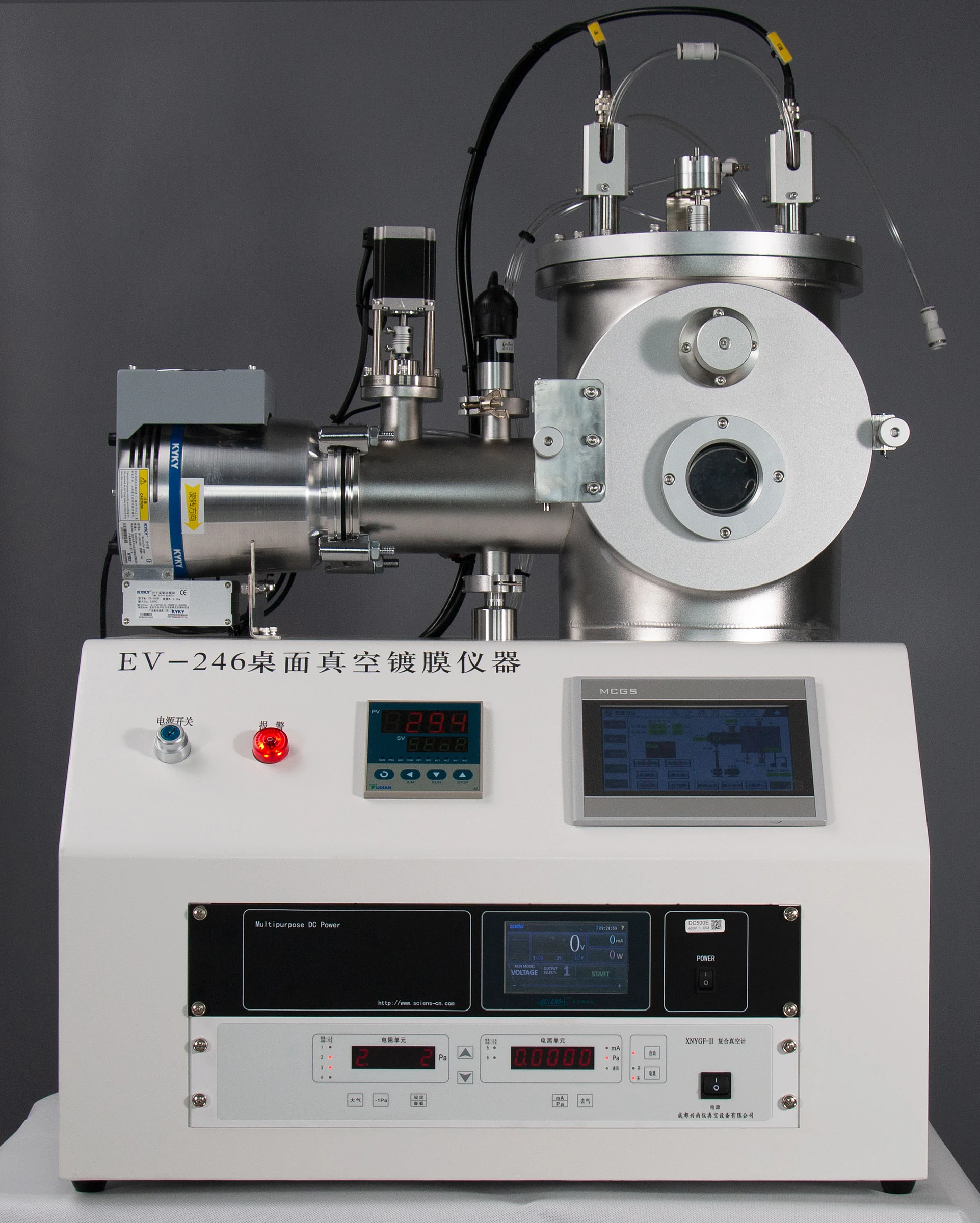
DM200-250
Review the DM200-250 when your requirement points toward a smaller research-oriented sputtering platform. Confirm the actual substrate, target arrangement, temperature requirement and deposition task on the model page before selection.
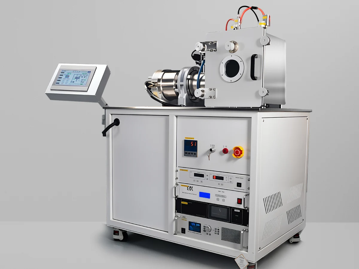
DM300
The DM300 has its own existing model page for model-specific configuration. Use the requirement defined in the previous sections to check whether its chamber, target, substrate and process options match your deposition task.
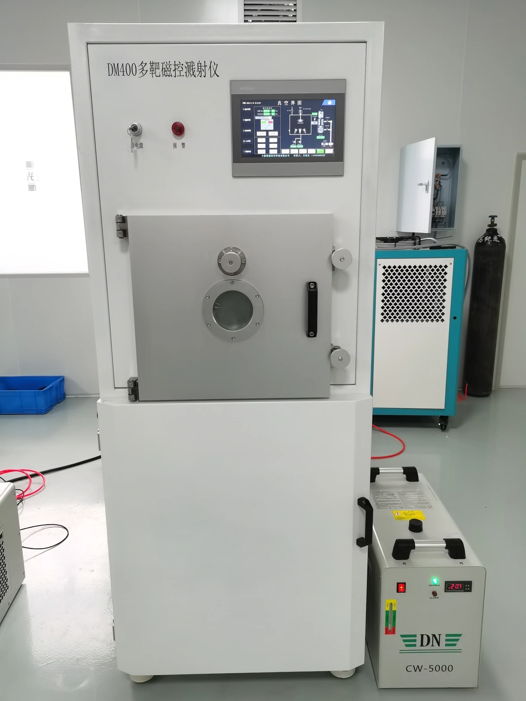
DM400
Use the DM400 product page to review the current model-specific system arrangement. Selection should still be based on the actual film, substrate, source configuration and vacuum requirement, rather than assuming capabilities from the model name.

DM500
The DM500 is another existing DM-series model route. Review its current product-page configuration against your target materials, substrate dimensions, film structure and operating workflow before making a model decision.
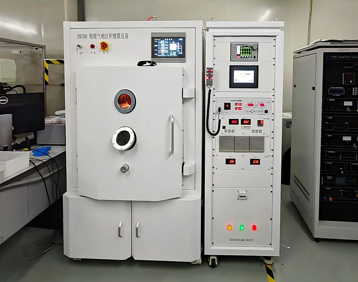
DM700
DM700 represents the largest of the five currently linked DM-series magnetron sputtering model pages. Use it as a model-level route when your project requires evaluation of a larger chamber, larger workpiece or higher batch requirement, while confirming the actual target, power, substrate and vacuum configuration from the current technical data.
Compare Models with the Same Requirement Checklist
When reviewing DM model pages, compare the same engineering inputs instead of comparing model names alone.
| Compare | What to Check | Why It Matters |
|---|---|---|
| Substrate | Size, shape, quantity and temperature limit | Determines chamber space and substrate handling |
| Targets | Material count, source arrangement and power route | Determines single-target, multi-target and co-sputtering needs |
| Film Requirement | Layer structure, thickness and uniformity target | Affects geometry, motion and acceptance criteria |
| Vacuum Workflow | Loading frequency, isolation and contamination needs | Affects chamber and vacuum architecture |
| Scale | Research, pilot, batch and throughput requirement | Determines whether the platform fits the real operating task |
| Site Conditions | Installation space and project utilities | Must be checked before quotation and final layout |
After narrowing the model route, the next step is to define what must be verified before purchase: vacuum performance, process functions, film acceptance, system boundaries and the data that should be agreed before the final quotation.
Review Engineering & Verification →Define the Acceptance Criteria Before the Sputtering System Is Quoted
A technical quotation should define more than a chamber, pump and power supply. The buyer and supplier should agree on vacuum performance, target and power configuration, substrate conditions, film acceptance requirements, monitoring functions and control scope before the final system configuration is confirmed.
Define Ultimate Vacuum and Pump-Down Conditions
Vacuum performance should be confirmed using the actual model or project specification. Ultimate vacuum and evacuation time depend on the chamber, pumping configuration and test conditions. If leak rate or pressure-hold performance is important to the application, these should also be specified as separate acceptance items.
Verify the Actual Hardware Included in the System
The quotation should clearly identify the selected target quantity and size, DC / RF power route, vacuum pumps, gas-control channels, substrate handling and thermal configuration. Options discussed during technical evaluation should not be assumed to be included unless they appear in the final configuration.
Turn Film Thickness and Uniformity into Acceptance Criteria
If film thickness or uniformity is part of the purchasing requirement, define how it will be evaluated. A phrase such as “good film uniformity” does not define the substrate size, measurement positions, test film, measurement method or allowable variation.
Specify What Must Be Controlled, Monitored or Recorded
Control requirements can range from manual operation to touchscreen or PLC-based workflows. If the project requires thickness monitoring, data logging, additional vacuum diagnostics or process monitoring, identify these requirements before the system configuration is finalized.
Engineering Verification Checklist
These items help convert the selected system into a clear quotation and acceptance scope.
| Verification Item | Define Before Order | Verification Basis |
|---|---|---|
| Vacuum Performance | Ultimate vacuum and required pump-down target | Vacuum-gauge reading under agreed test conditions |
| Leak / Pressure Hold | Whether the project requires a separate leak or pressure-hold criterion | Agreed test method and acceptance value |
| Sputtering Sources | Target quantity, target size and DC / RF power route | Installed cathode and power-supply configuration |
| Substrate System | Size, rotation, heating, cooling, bias or fixture requirements | Functional verification of the agreed configuration |
| Gas Control | Process gases, reactive gases and required flow-control channels | Installed gas-control configuration and operating test |
| Film Thickness | Required film and target thickness | Agreed measurement method and sample |
| Film Uniformity | Substrate area and acceptable variation | Defined measurement points and acceptance calculation |
| Control & Monitoring | Manual / touchscreen / PLC operation and required monitoring functions | Functional operation and alarm / interlock checks |
| Site Interface | Installation space, cooling, utilities and required project interfaces | Confirmed interface and installation checklist |
Verify the Real Equipment — Not Only the Configuration List
Real equipment images help confirm the mechanical form, cabinet arrangement and physical configuration of the system. Final acceptance should still follow the agreed technical specification.
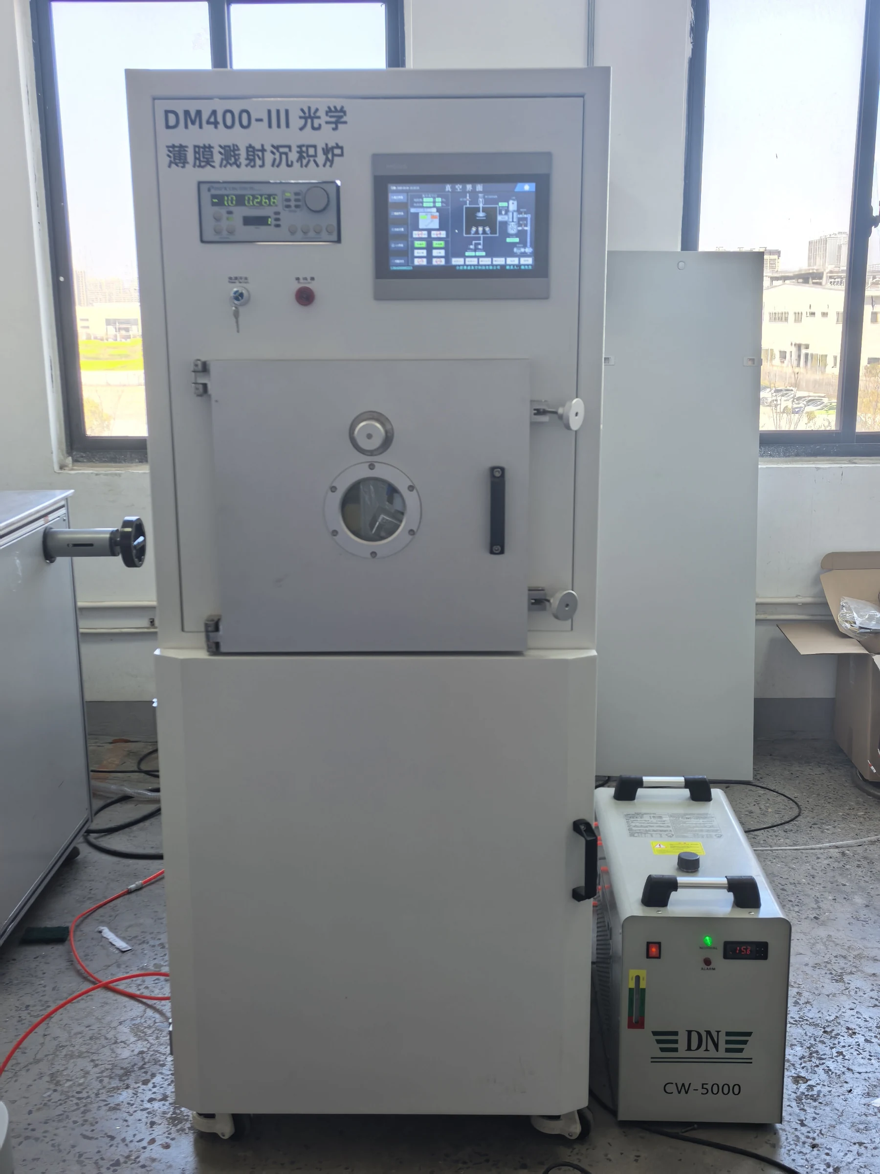
Representative DM400 equipment image for reviewing the physical system arrangement. Model-specific technical configuration should be confirmed against the final quotation.
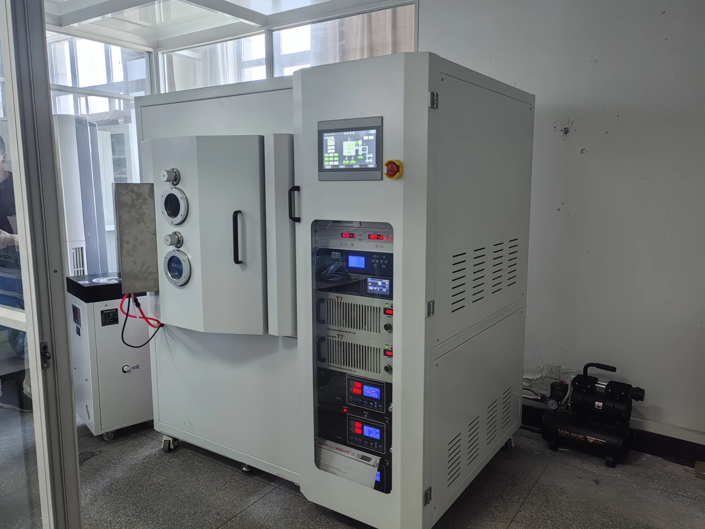
Representative DM700 system view showing a larger equipment architecture. Performance and acceptance criteria remain model- and project-specific.
Public product pages should define what performance must be verified and what the buyer needs to specify. Detailed PLC logic, interlock thresholds, internal I/O maps, source tuning procedures and process recipes belong in project engineering documentation rather than the public website.

With the system route and acceptance logic defined, the next section answers the common questions buyers ask before requesting a magnetron sputtering system quotation.
Continue to FAQ →Common Questions Before Selecting or Quoting a Sputtering System
These questions address the decisions buyers commonly face before specifying a magnetron sputtering system: power mode, target quantity, vacuum level, film uniformity, target size and the information needed for a useful quotation.
01 What is the difference between DC and RF magnetron sputtering?
DC magnetron sputtering is commonly used with electrically conductive targets. RF sputtering is commonly evaluated when the target is insulating or dielectric and conventional DC operation is not suitable.
The choice should follow the actual target material and required film rather than treating RF as simply a higher-level version of DC.
Review DC / RF Process Selection →02 Should I use RF or DC sputtering for dielectric films?
For an insulating or dielectric target, RF sputtering is commonly the starting route because charge accumulation can make conventional DC operation unsuitable.
However, the final process route still depends on whether the film is deposited from a dielectric target or formed through another route such as reactive sputtering.
03 When should reactive sputtering be used?
Reactive sputtering is considered when a reactive gas participates in forming the required compound film during deposition.
Compared with non-reactive sputtering, the system specification may need additional consideration of gas control, target behavior, process stability and the required film composition.
04 What is the difference between co-sputtering and sequential sputtering?
In sequential sputtering, different materials are deposited in separate steps to build a layer sequence.
In co-sputtering, more than one source is used during the same deposition stage when the film-development task requires simultaneous material contribution.
The required film structure determines which target arrangement should be evaluated.
05 How many sputtering targets do I need?
The number of targets should follow the number of materials and the required deposition sequence.
One material may only require one source. Multilayer development, frequent material switching or co-sputtering can justify multiple target positions. Future research flexibility can also be considered when the system architecture is selected.
Review Target & System Configuration →06 What base pressure is needed for magnetron sputtering?
There is no single base-pressure value that should be applied to every sputtering project.
The required vacuum level depends on the material system, contamination sensitivity, film objective, chamber configuration and process requirement. For purchasing, define the required ultimate vacuum or base-pressure target at the model or project level rather than relying on a generic family value.
Review Vacuum Verification →07 What target size is needed for sputtering?
Target size should be evaluated together with the substrate and deposition geometry.
Important inputs include substrate dimensions, required coating area, source-to-substrate arrangement, target material and expected process scale. Target diameter alone does not determine film uniformity or system suitability.
08 How can sputtering film uniformity be improved?
Film uniformity is affected by the complete deposition arrangement, including source geometry, substrate size and position, substrate motion, process conditions and the way uniformity is measured.
For equipment procurement, the more useful question is not simply “is the system uniform?” but “what substrate area, test film, measurement positions and allowable variation define acceptance?”
09 How much does a magnetron sputtering system cost?
The price depends on the selected equipment architecture, not only the model name.
Major cost drivers can include chamber size, number of sputtering sources, DC / RF power configuration, vacuum system, substrate heating or motion, gas control, monitoring and automation requirements.
A useful quotation therefore starts with the deposition requirement rather than a request for a generic system price.
Request a Project-Based Quotation →Give Us the Deposition Task, Not Only a Model Number
A quotation becomes much more useful when it starts from the material, substrate, film requirement and operating task. These inputs allow the system route and model to be evaluated before optional hardware is added.
If you already know your material and substrate, the next step is to submit the requirement for a system and model evaluation.
Request a System ProposalSend the Deposition Requirement — Then Select the System
A useful magnetron sputtering system quotation starts from the deposition task rather than a model number alone. Send the target material, substrate, film requirement, batch requirement and site conditions so the appropriate DM-series platform and project configuration can be evaluated.
Prepare These Six Inputs
You do not need to prepare a complete technical specification. These inputs are enough to start the first system-selection review.
If you already have a DM200-250, DM300, DM400, DM500 or DM700 in mind, include it. If not, start with the project requirements and let the model be selected afterward.
Request a System & Model Evaluation
Send the information you already have. The first review can be based on partial project data; missing technical details can be clarified during the next step.
If you are unsure about target count, DC vs RF, chamber size or the suitable DM model, send the material and substrate information first.
Include drawings, sample photos or an existing technical specification if available.
For a useful proposal, the most important starting information is what you need to deposit and on what substrate. The equipment model, target arrangement and optional functions can then be evaluated around that requirement.
