
LOW-VOLTAGE SHORE POWER SYSTEM
Industrial Low-Voltage Shore Power Systems for Shipyards and Commercial Vessels
Configure industrial three-phase shore power around the vessel voltage, frequency, load profile, cable route and required connection scope.
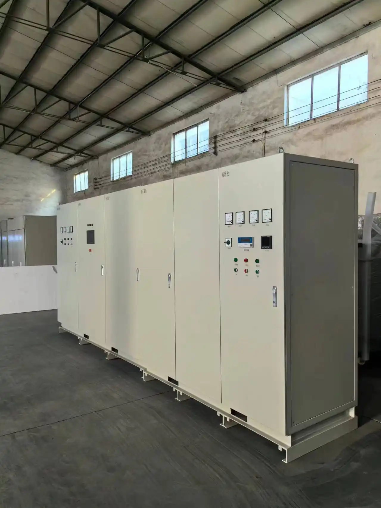
SDACME supplies project-engineered low-voltage shore power systems for shipyards, dry docks, vessel maintenance and commercial vessels with low-voltage onboard distribution. The system can be supplied as core conversion equipment or as an integrated package with transformers, switchgear, protection, monitoring and connection equipment.
300–3000kVA Reference Range
Engineering capacity for industrial vessel loads rather than small consumer shore-power applications.
380V to 480V Project Voltages
Typical project outputs include 380V, 400V, 415V, 440V, 450V and 480V.
50Hz / 60Hz Conversion
Configure 50Hz-to-60Hz or 60Hz-to-50Hz conversion according to shore-grid and vessel requirements.
Flexible Supply Scope
Select a low voltage shore power converter alone or an integrated low voltage shore connection system.
TECHNICAL RANGE
Typical Low-Voltage Shore Power Specifications
Low-voltage shore power systems are engineered around the available shore-side supply and the vessel’s required voltage, frequency and load profile. The ranges below show typical configurations used for project planning.
Typical Technical Range
Low-Voltage System Configurations
| Parameter | Typical Range or Configuration |
|---|---|
| Capacity | 300–3000kVA |
| Project Voltages | 380V / 400V / 415V / 440V / 450V / 480V |
| Frequency Conversion | 50Hz to 60Hz or 60Hz to 50Hz |
| Power Conversion | Static IGBT frequency conversion for low-voltage applications |
| Local Control | HMI and PLC-based operating control |
| Communication | RS232, RS485, CAN or Profibus interfaces can be selected for the control system |
| Installation | Indoor cabinet, outdoor enclosure or containerized integration |
Typical Project Configurations
Shore-Side Input and Required Vessel Output
| Shore-Side Input | Required Vessel Output | System Direction |
|---|---|---|
| 380V / 50Hz | 380–480V / 60Hz | Low-voltage frequency conversion for industrial vessel loads |
| 400V or 415V / 50Hz | 440V / 60Hz | Combined voltage and frequency conversion |
| 440V / 60Hz | 400V or 415V / 50Hz | 60Hz-to-50Hz shore power conversion |
SYSTEM CONFIGURATION
Low-Voltage Shore Power Configuration and System Integration
A low-voltage shore power system can combine power conversion, voltage matching, distribution, protection, monitoring and vessel connection equipment in one coordinated electrical package.
Typical Electrical Path
From the Shore-Side Grid to the Vessel Main Switchboard
- 01 Shore-Side Grid
- 02 Input Switchgear and Protection
- 03 Voltage-Matching Transformer
- 04 Low-Voltage Shore Power Converter
- 05 Output Distribution and Metering
- 06 Shore Connection Equipment
- 07 Vessel Main Switchboard
The configuration can be adapted to equipment already available at the port or shipyard, allowing the new shore power system to connect with the existing electrical infrastructure and vessel interface.
Integrated Electrical Equipment
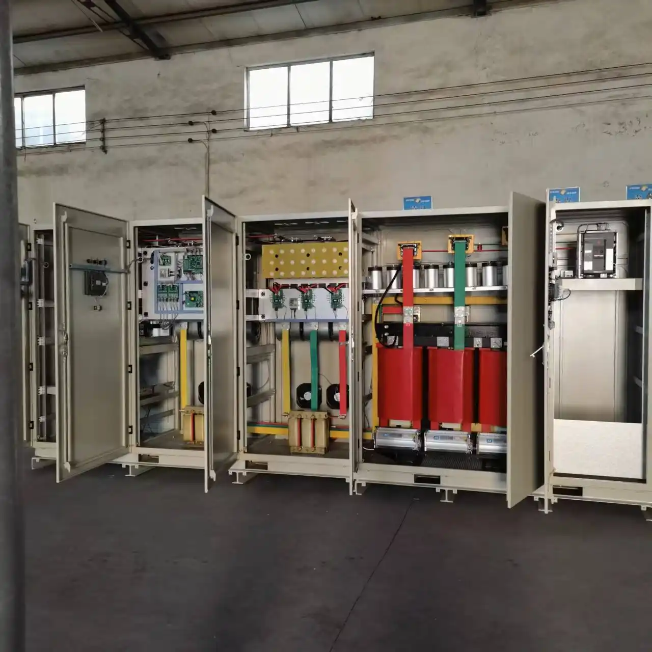
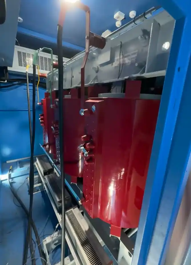
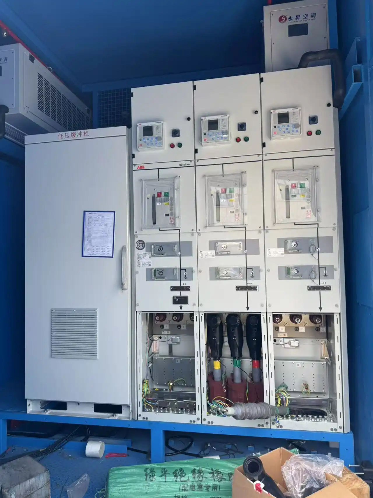
Converter, Transformer and Switchgear Integration
The converter is combined with voltage-matching, distribution and protection equipment according to the shore-side supply and the electrical requirements of the vessel.
CONTROL & PROTECTION
Control, Protection and Operating Visibility
The control and protection system coordinates converter operation, output settings, vessel connection, load changes and abnormal operating conditions.
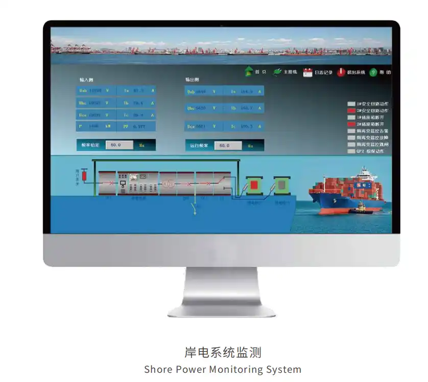
Operating Visibility
Local Monitoring Through the HMI and PLC
The operating interface can provide the information required to start, stop, monitor and diagnose the shore power system during vessel connection and normal use.
Communication interfaces can connect the local HMI and PLC to an external monitoring platform or central control system.
System Functions
Control, Protection and Communication Functions
Voltage and Frequency Setting
Set the required output voltage and frequency through the local control interface within the configured operating range.
Phase-Sequence Adjustment
Phase-sequence adjustment can be configured to support vessel connection and commissioning requirements.
Reverse-Power Handling
Reverse-power detection, control or trip logic can be included when required by the operating sequence.
Electrical Protection
Protection can include overcurrent, overload, short circuit, overvoltage, undervoltage, abnormal frequency, phase conditions, imbalance and overtemperature.
Monitoring and Records
Operating parameters, alarms, historical information and fault records can be collected by the control system.
Communication Interfaces
RS232, RS485, CAN or Profibus interfaces can connect the local HMI and PLC with external or central control systems.
Typical Protection Coverage
Electrical and Equipment Protection
Protection settings, interlock logic, communication interfaces and remote-control functions are selected to match the vessel connection, equipment arrangement and operating requirements.
INSTALLATION OPTIONS
Indoor, Outdoor or Containerized Low-Voltage Installation
The electrical configuration and installation format are selected separately according to the available space, site environment, cable route, equipment arrangement and maintenance requirements.
Installation Planning
Select the Equipment Format Around the Site
The same low-voltage shore power function can be arranged inside an electrical room, installed in an outdoor enclosure or integrated into a containerized package. The preferred format depends on the port or shipyard layout and the conditions surrounding the equipment.
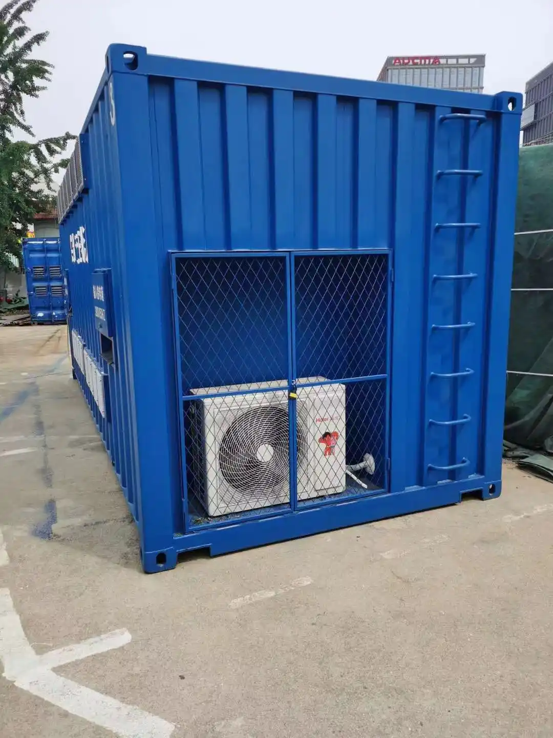
Installation Formats
Three Ways to Arrange the Low-Voltage Equipment
Indoor Cabinet Installation
For Dedicated Electrical Rooms
Suitable for ports or shipyards with an electrical room, practical equipment access, suitable ventilation and an established cable route.
- Room dimensions and equipment clearance
- Ventilation or air-conditioning conditions
- Input and output cable access
- Inspection and maintenance space
Outdoor Enclosure
For Equipment Installed Outside
Suitable where the equipment must be positioned outdoors and the enclosure, cooling, cable entry and maintenance arrangement can be adapted to the local environment.
- Weather and environmental exposure
- Cooling and internal heat removal
- Condensation and corrosion control
- Outdoor maintenance access
Containerized Package
For Factory-Integrated Equipment Packages
Suitable where the project benefits from pre-arranged cabinets, internal wiring, cooling equipment and a compact packaged installation.
- Container dimensions and equipment layout
- Internal wiring and cable routing
- Cooling and air-flow arrangement
- Lifting, transport and site positioning
Site and Enclosure Planning
Conditions That Shape the Installation Design
Enclosure construction, cooling, anti-condensation measures, corrosion protection, cable entry and lifting arrangements are selected to match the installation location and equipment package.
MANUFACTURING & FAT
Factory Integration and Shore Power System Testing
Low-voltage shore power equipment can be assembled, internally wired, inspected and functionally tested before shipment. This helps verify the electrical connections, control functions, output performance and protection logic of the integrated equipment package.
Factory Integration
Equipment Preparation Before Shipment
Where the system includes multiple cabinets, transformers, switchgear or packaged equipment, the main electrical components can be arranged and connected as one coordinated system before delivery.
- 01 Cabinet and Equipment Assembly Arrange converter cabinets, control equipment, switchgear and other system components.
- 02 Internal Wiring and Identification Check cables, busbars, terminals, labels and component identification.
- 03 Power-On and Functional Checks Review start-up logic, HMI displays, alarms, metering and operating functions.
- 04 Output and Protection Testing Verify voltage, frequency, operating response, alarms and protection functions.

Factory Inspection and Testing
Typical Checks for Low-Voltage Shore Power Equipment
| Factory Activity | What Is Checked |
|---|---|
| 01 Visual and workmanship inspection | Cabinet construction, component installation, labels, terminals and general workmanship. |
| 02 Component and wiring verification | Internal wiring, busbars, terminals, cable connections and equipment identification. |
| 03 Insulation and electrical safety testing | Insulation or withstand-voltage testing can be included where it is suitable for the selected equipment. |
| 04 Control-power and functional checks | Start-up sequence, local HMI, metering, alarms, operating controls and shutdown functions. |
| 05 Output verification | Output voltage, frequency, regulation and control response under the available test conditions. |
| 06 Protection and interlock testing | Alarm, trip, emergency-stop and electrical interlock functions included in the system. |
| 07 No-load or load testing | Operating performance can be tested at no load or with an available test load selected for the equipment configuration. |
Manufacturing and Test Evidence
Internal Wiring Inspection and Factory Acceptance Testing
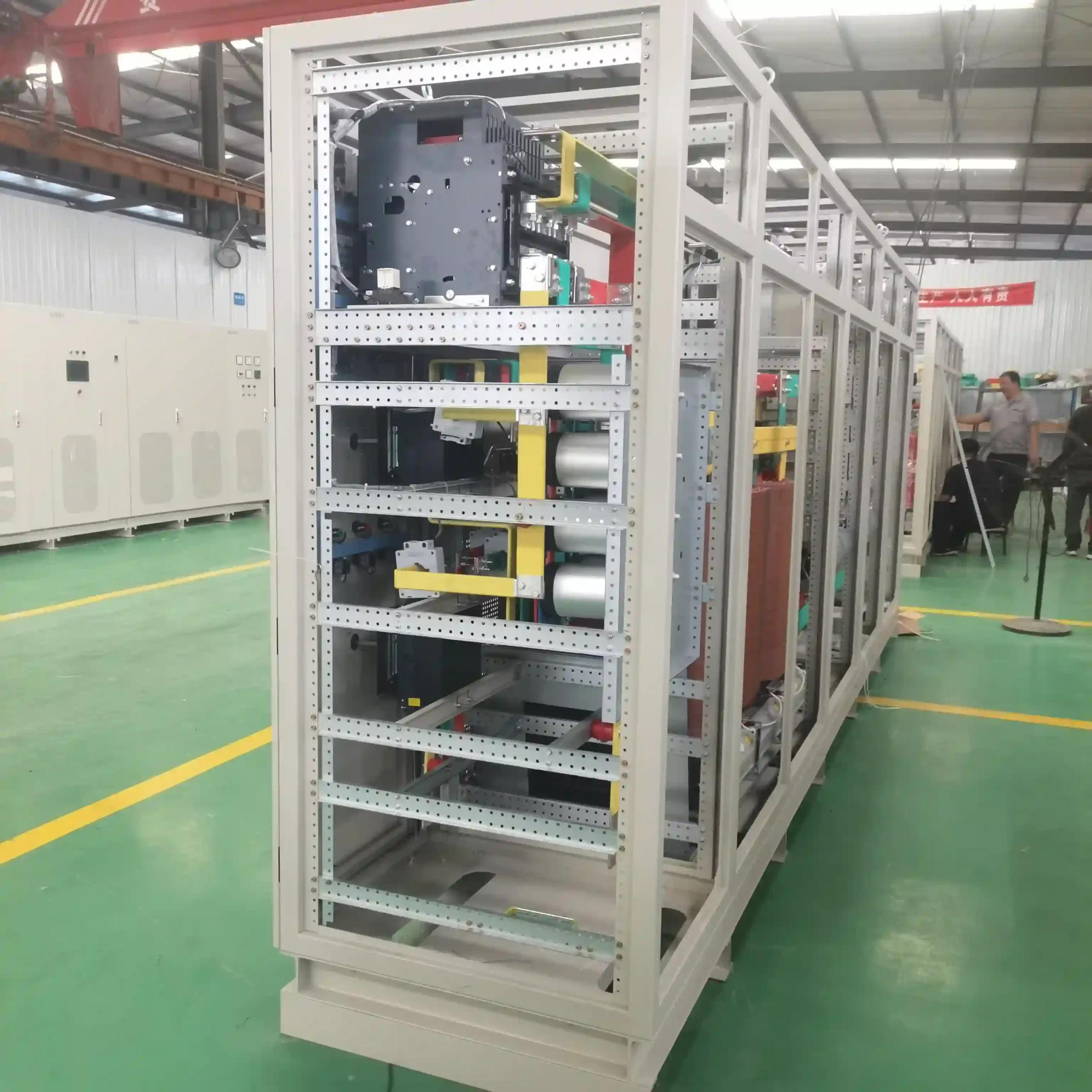
Cable connections, terminals, components and identification are checked during equipment preparation.
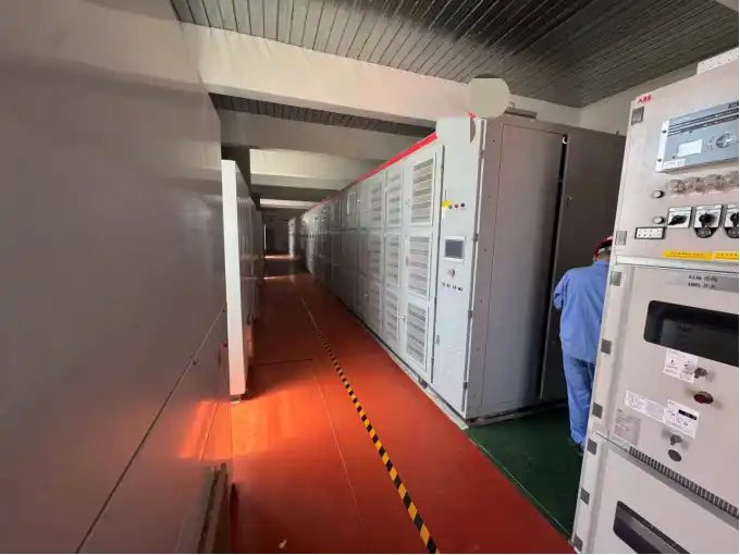
Output, control, monitoring, alarm and protection functions can be reviewed before the equipment is prepared for shipment.
PROJECT REFERENCES
Selected Low-Voltage Shore Power References
These projects show how low-voltage shore power equipment can be configured for different shipyard input conditions, vessel voltages, power capacities and installation formats.
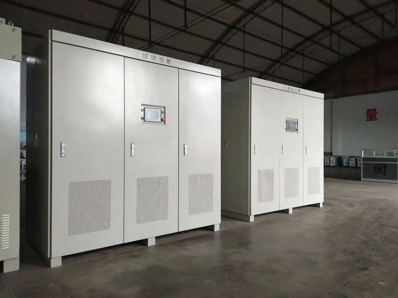 400kVA
 400kVA Containerized Low-Voltage Shore Power System
A 400kVA containerized shore power system was supplied for a shipyard project in Singapore. The system converts the available 415V / 50Hz shore-side supply to 415V / 60Hz power for vessel use.
- Capacity
- 400kVA
- Shore Input
- 415V / 50Hz
- Vessel Output
- 415V / 60Hz
- Installation
- Outdoor container
- Application
- Shipyard shore power
- Project Status
- Delivered and operating
The equipment was delivered, commissioned and placed into operation for the shipyard application.
Two 1200kVA Low-Voltage Shore Power Units
Two 1200kVA shore power units were supplied for an Indonesian shipyard. The equipment accepts the local 380VAC / 50Hz supply and provides adjustable 380–480VAC / 60Hz output for vessel electrical loads.
- Quantity
- 2 units
- Capacity
- 1200kVA each
- Shore Input
- 380VAC ±15%
- Input Frequency
- 50Hz ±5%
- Vessel Output
- 380–480VAC / 60Hz
- Project Status
- Delivered and operating
Both units were delivered, commissioned and placed into operation at the shipyard.
 2 × 1200kVA
 Equipment Example
300kVA Vessel Shore Connection Converter
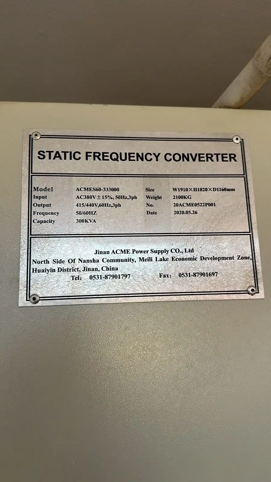
This 300kVA static frequency converter nameplate shows a three-phase 380VAC / 50Hz input and 415V or 440V / 60Hz output for vessel shore connection.
The electrical configuration is selected around the shore-side supply and the voltage and frequency required by the connected vessel.
