
Shore Power Load Testing: What to Verify Before the First Vessel Connection
A shore power system should not be accepted only because it starts, shows the correct voltage and runs without load.
Before the first vessel connection, the project team needs evidence that the equipment has been inspected, energized, protected correctly and tested under the agreed operating conditions. Factory acceptance testing, load testing, site commissioning and the first vessel connection answer different questions.
A no-load run can confirm that the converter starts. It cannot show how the system regulates voltage at full load, responds to a sudden load change, handles an unbalanced condition or behaves after temperatures have stabilized.
The test scope therefore has to follow the actual shore power configuration, voltage level, capacity, transfer method and project acceptance requirements.
The first vessel should not become the first real test of basic wiring, protection or interlock logic. Those issues should be found earlier during FAT, load testing and site commissioning.
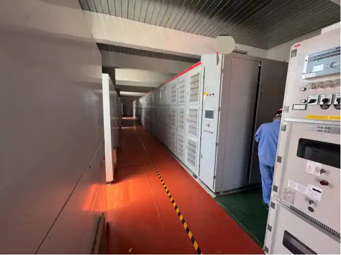
FAT, Load Testing, SAT and First Vessel Connection Are Different Stages
Factory acceptance testing checks the supplied equipment before shipment.
Depending on the project scope, FAT can include mechanical inspection, wiring checks, insulation and withstand tests, protection verification, control and communication checks, interlocks and agreed load-performance testing.
A load test applies a controlled electrical load so that voltage, current, frequency, power quality, temperature and dynamic response can be observed under conditions that cannot be demonstrated at no load.
Site acceptance testing verifies the installed system after delivery. Site cables, grounding, final protection settings, communication interfaces, connection equipment and external interlocks are now part of the test boundary.
The first vessel connection introduces another layer: the real shipboard electrical system, the shore connection cable, the vessel switchboard and the actual transfer sequence.
These stages should support each other. The first vessel should not be used to discover a basic wiring, protection or interlock error that could have been found during FAT or site commissioning.
Our shore power manufacturing and FAT page explains how factory inspection, testing and site support fit into the complete delivery process.
Begin with Assembly and Documentation Checks
Load testing should not be the first inspection of the equipment.
Before high voltage is applied, check that the assembled system matches the approved drawings and equipment schedule.
The inspection can include:
- Equipment and cabinet nameplates
- Transformer data
- CT and PT data
- Cable and terminal identification
- Busbar and phase identification
- Main-circuit connections
- Tightening and mechanical condition
- Protective grounding
- Cabinet and coating condition
- Internal wiring
- Installed control and protection devices
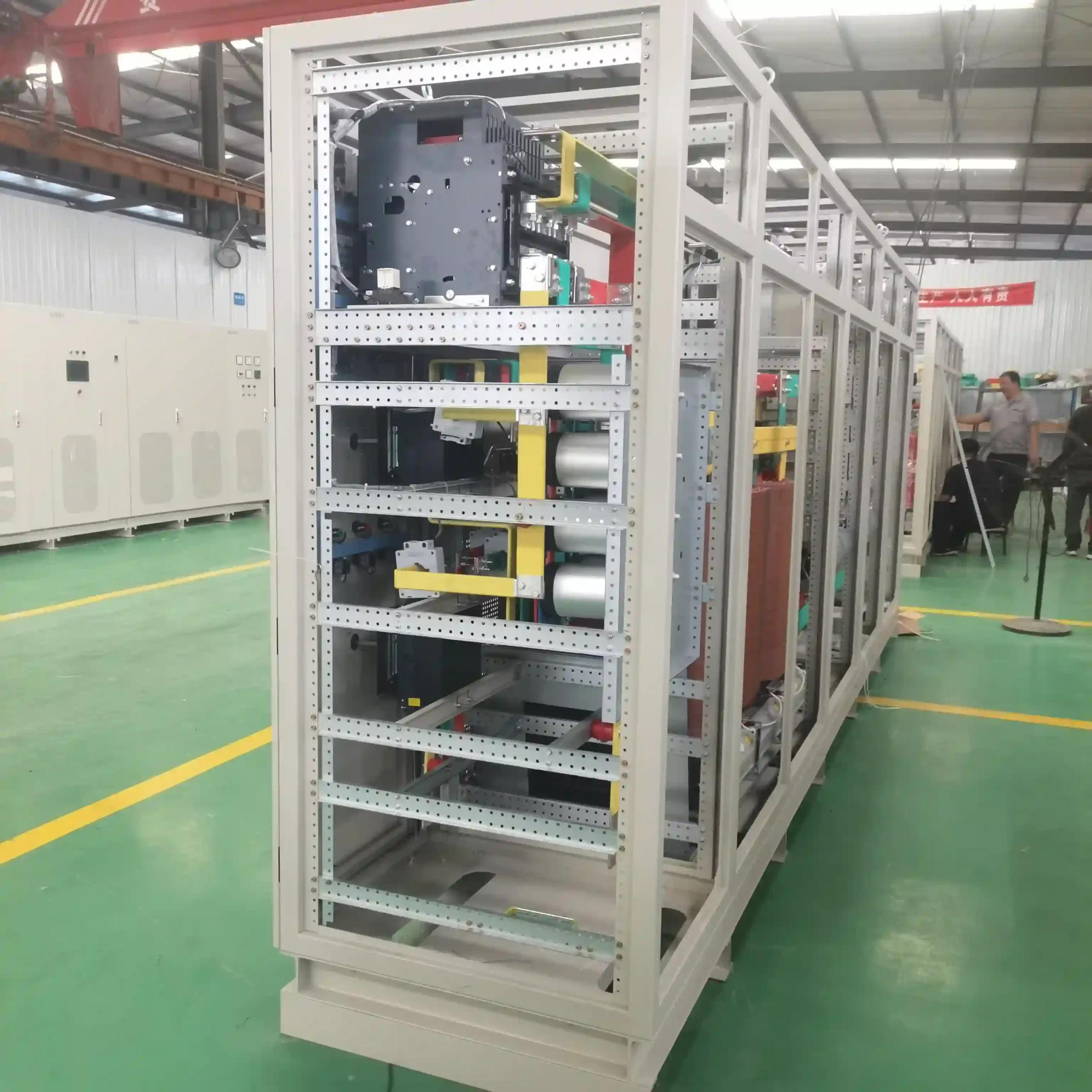
A project test procedure used in shore power systems jointly delivered by SDACME and its project partners also recorded major components for later traceability.
That matters after commissioning. If a CT, transformer temperature controller, protection device or other component later needs replacement or technical support, the project team should be able to identify what was actually installed.
Internal wiring also needs to be checked against the drawings. A powered HMI does not prove that every protection input, breaker status or trip output is connected correctly.
Insulation, Withstand and Safety Interlock Checks
Electrical integrity has to be verified before normal operation.
Insulation and withstand tests confirm that the relevant circuits can withstand the test condition defined for the equipment and voltage class.
High-voltage testing also requires a controlled test area. Personnel, barriers, grounding and test connections are part of the test procedure, not administrative details added afterward.
Components that must not remain connected during the test, such as particular measuring or surge-protection devices, should be handled according to the approved procedure.
Interlocks should be checked at the same stage.
If a compartment is not intended to be opened while energized, the mechanical and electrical arrangement should prevent unsafe access according to the approved design.
A test record should identify what was tested, the test boundary, the applied condition and the result. “PASS” alone has limited value if the reader cannot determine what circuit or function was actually checked.
Power-On and I/O Verification
After the basic electrical checks, power-on testing should confirm the control and auxiliary systems.
Useful checks include:
- Auxiliary and control power
- PLC operation
- HMI communication
- Transformer temperature indication
- Breaker and switch status
- Cabinet-door or electrical interlocks
- High-voltage indication
- Cooling and environmental equipment
- Input and output measurement channels
- Alarm and status signals
In one project test procedure, PLC communication, transformer temperature indication, electromagnetic door locking and high-voltage indication were checked before full-load operation.
Measurement channels also need to be verified against the correct phase and location.
An output-current value shown on the screen is useful only when the CT ratio, phase assignment and displayed value correspond correctly. The same principle applies to voltage, current, frequency and zero-sequence signals.
A point-by-point test record should show that a simulated or actual input produces the intended alarm, indication, block or trip response.
Protection and Interlock Testing
Protection should be tested with the settings approved for the project.
Depending on the system configuration, the protection scope may include:
- Overvoltage
- Undervoltage
- Overcurrent
- Overload
- Phase loss
- Phase unbalance
- Frequency abnormality
- Earth-fault or zero-sequence protection
- Reverse-power protection
- Transformer or converter overtemperature
Not every shore power system uses the same protection functions or the same thresholds.
The purpose of the test is not simply to generate an alarm once. The complete protection chain should perform as designed.
Interlocks also need both positive and negative testing. It is not enough to prove that a breaker can close under the correct condition. The team should also confirm that it cannot close when a required permissive is absent.
For the wider relationship between project requirements, protection and applicable design frameworks, see our shore power standards and compliance page.
Staged Load Testing
Going directly from no load to full load gives less information than a controlled staged test.
Staged loading lets the team compare electrical performance as current increases and identify abnormal regulation, heating or phase behavior before the system reaches its maximum test point.
In one shore power project jointly completed by SDACME and its project partners, the approved test procedure used 30%, 60% and 100% of rated capacity as load points.
At 100% rated load, operation continued until the temperature had stabilized and then remained at full load for a further one hour.
The recorded parameters included:
- Voltage
- Current
- Frequency
- Active power
- Reactive power
- Power factor
- Harmonic performance
- Three-phase unbalance
- Equipment efficiency
These values describe one project test procedure. They are not automatic acceptance requirements for every shore power system.
A new project should define its load points, test duration and acceptance limits before FAT begins.
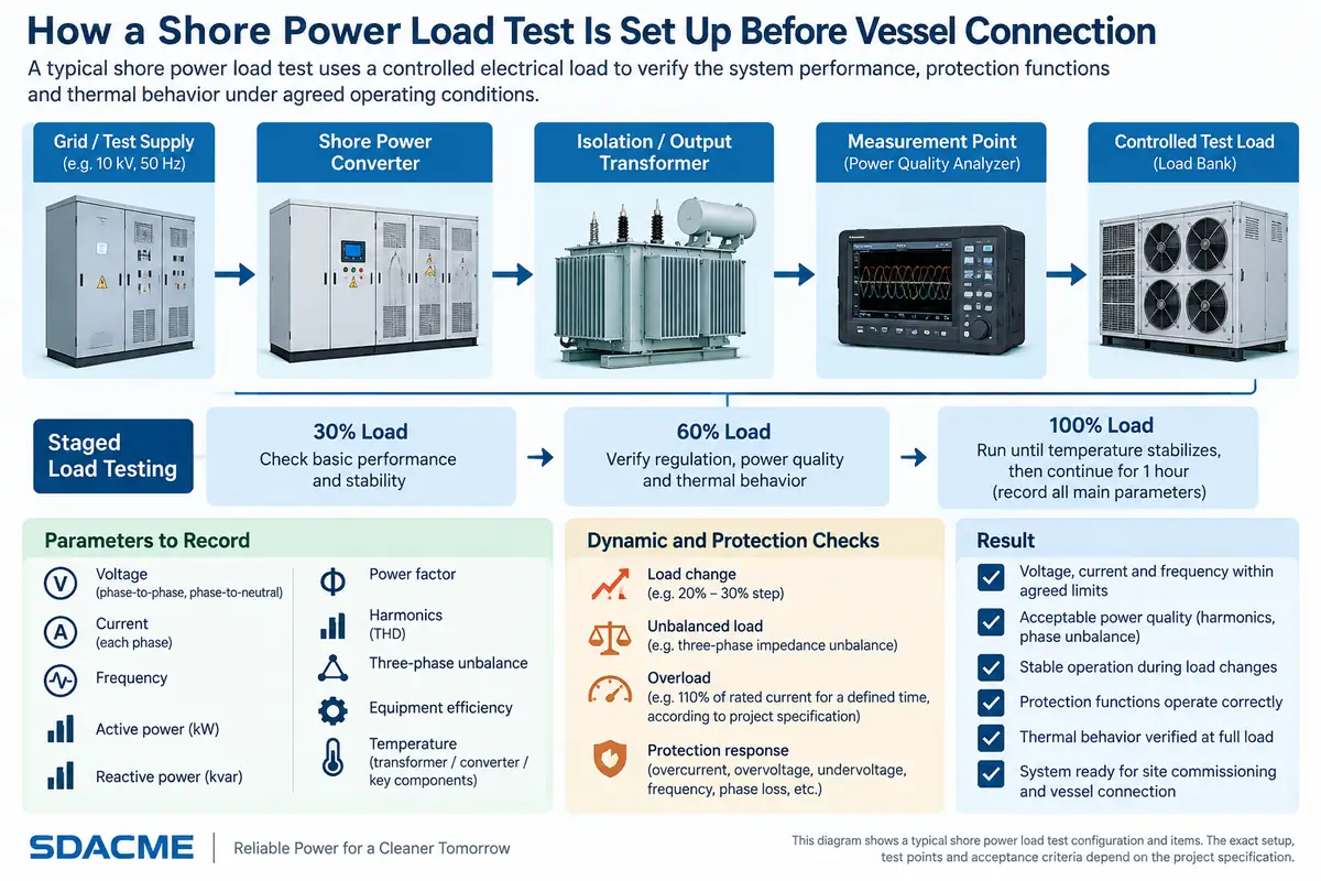
The test setup matters as well. Load equipment, transformers, cables, ventilation and connections must be suitable for the required voltage, current, frequency and test duration.
Load Steps, Unbalance and Overload
A steady load cannot demonstrate every condition that the system may experience when supplying a vessel.
Load changes
When a significant load is added or removed, the system should maintain acceptable voltage and frequency behavior and recover within the agreed limits.
One jointly implemented shore power test procedure used a 20% to 30% load adjustment to evaluate voltage waveform and transient response.
The practical question is not only whether the system can carry a steady load, but how it responds when vessel demand changes quickly.
Unbalanced load
Vessel loads are not always perfectly balanced across all three phases.
Testing with an agreed unbalanced condition can show whether the shore power system maintains acceptable phase voltages and control stability. The allowable unbalance should be defined by the applicable project requirement rather than copied from another project.
Overload
Overload performance is another project-defined test.
In one jointly delivered project procedure, the shore power system was tested at 110% of rated output current for 60 minutes.
The same procedure also included higher-current simulated protection checks.
These figures are useful project evidence, but they should not be interpreted as a universal SDACME product specification.
For a new project, the required overload level, duration and protection response should be agreed in the technical specification and FAT procedure.
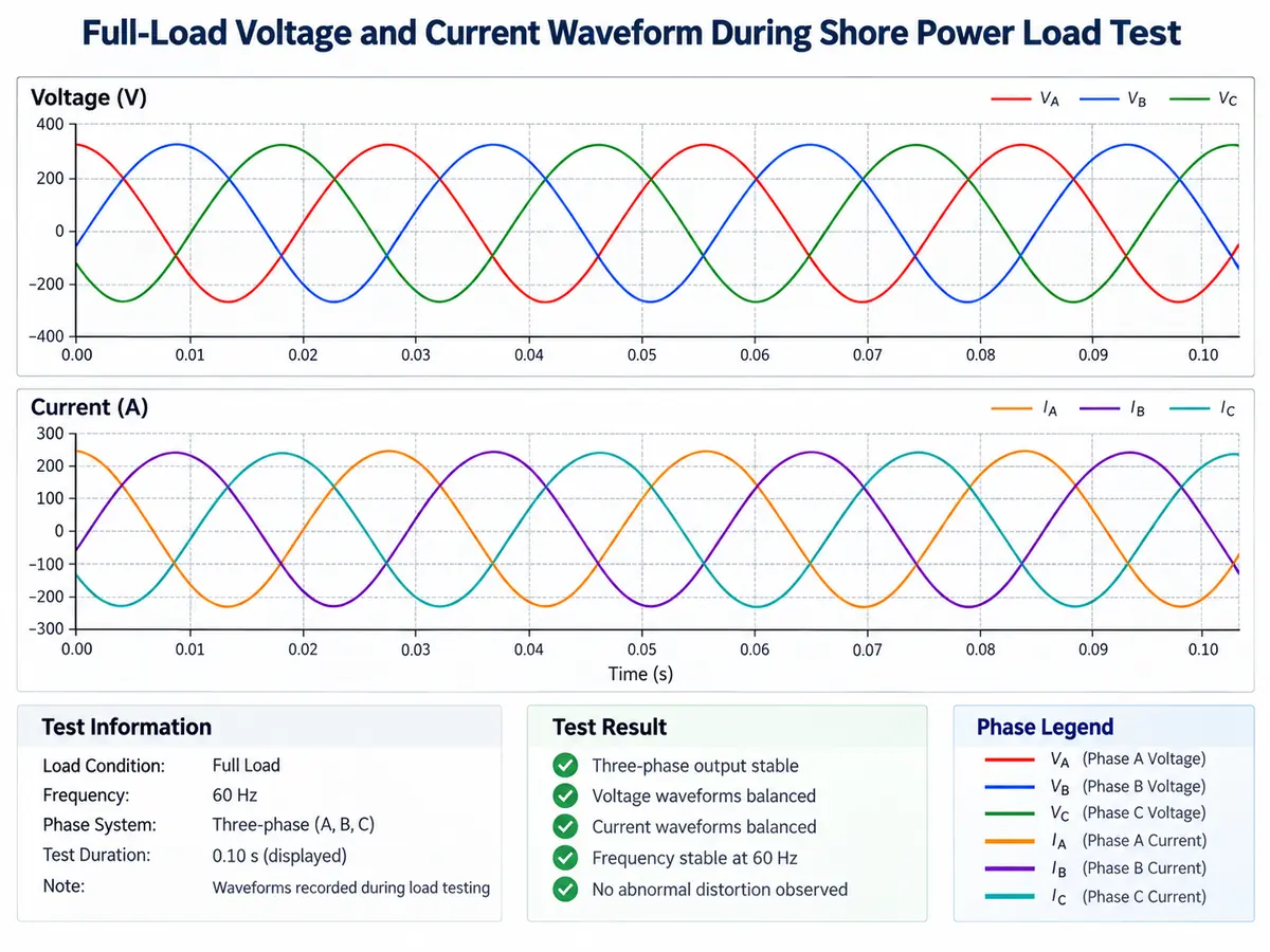
Cooling Performance During the Load Test
Full-load testing also gives useful information about the thermal design.
At low load, a cooling system may appear completely normal because the converter, transformer and conductors are producing relatively little heat.
Once the equipment operates continuously at full load, the test can reveal:
- Abnormal transformer temperature
- Converter thermal alarms
- Poor cabinet airflow
- Cooling-fan problems
- HVAC limitations
- Local hot spots
- Temperature rise that does not stabilize
The required temperature points depend on the actual equipment configuration.
For a containerized system, the project may monitor transformer temperature, selected converter temperatures, enclosure temperature and cooling-system status.
The run time is important. A short full-load test may prove that the converter can carry the current, but it may finish before the thermal system reaches a meaningful operating condition.
Factory testing still cannot reproduce every final site condition. Outdoor temperature, solar heating, installation clearances and final ventilation conditions can change the thermal result after installation.
For a deeper review of this issue, see how cooling and HVAC are sized for a containerized shore power system .
From SAT to the First Vessel Connection
After installation, the project moves from equipment testing to interface testing.
Before the first live vessel connection, confirm the final installation items that could not be completely verified at the factory, including:
- Site cable connections
- Grounding and bonding
- Phase sequence
- Final protection settings
- Communication interfaces
- Berth connection equipment
- Emergency-stop circuits
- Shore-to-ship safety interlocks
A jointly completed shore power project provides a useful example of this boundary. Before the first vessel was energized, the port-side and ship-side teams reviewed the intended operating procedure and inspected the vessel shore-power equipment.
After the shore cable was connected, the safety interlock circuit was tested before energization.
Once shore power reached the incoming side of the vessel main switchboard, the shipboard team checked phase sequence, voltage and frequency before the approved transfer sequence continued.
That is why the first vessel connection should be treated as a controlled commissioning stage, not as a substitute for FAT or SAT.
For the electrical information that should be exchanged before connection, see our shore power selection and compatibility guide .
Transfer Method Must Be Defined Before Testing
The acceptance plan also needs to identify how the vessel will transfer between ship generation and shore power.
A break-before-make transfer and a synchronized no-break transfer do not use the same test sequence.
Where temporary parallel operation is required, synchronization, transfer logic and reverse-power protection need to be verified according to the approved project procedure.
The acceptance team should know in advance:
- Who controls the transfer
- Which side performs synchronization
- Which permissives must be satisfied
- What happens if synchronization fails
- What happens if reverse power appears
- Which emergency action has priority
Detailed reverse-power behavior belongs to the transfer and protection design, but its required operation should still be included in the test plan where synchronized transfer is used.
What the Final Test Record Should Contain
The purpose of the final record is simple: someone should be able to understand what was tested months later without relying on the memory of the engineers who were present.
A useful acceptance package can include:
- Approved test procedure
- Acceptance criteria
- Test instrument information
- Visual and wiring inspection records
- Insulation and withstand results
- Measurement and I/O verification results
- Protection settings
- Protection test records
- Interlock test results
- Load-test data
- Voltage and current waveform records where required
- Thermal or temperature records where required
- Final site commissioning records
- First-vessel-connection records where included
Project-specific test values should remain attached to the configuration and procedure under which they were measured.
A result from one converter rating, voltage class or load arrangement should not automatically become the acceptance criterion for another system.
Frequently Asked Questions
Is a no-load test enough for shore power FAT?
No. A no-load test can verify startup and basic control functions, but it does not demonstrate voltage regulation, thermal behavior or dynamic response under representative load.
Must every shore power system be tested at 100% load?
Not necessarily. The required load level depends on the contract, system capacity, available test facilities and approved test procedure. Where full-load testing is included, it provides stronger evidence of electrical and thermal performance.
What is the difference between FAT and SAT?
FAT verifies the supplied equipment before shipment. SAT verifies the installed system and the final site interfaces after delivery.
Can the first vessel connection replace SAT?
No. Basic installation, grounding, protection, phase sequence, communication and safety-interface checks should be completed before a live vessel becomes part of the test.
Should overload testing use the same values for every shore power system?
No. Overload level, duration and protection response should come from the approved project specification. Values used in one completed project should not automatically be copied to another configuration.
Who should witness the shore power test?
That depends on the project. The supplier, customer, consultant, classification society or third-party inspector may witness defined stages. Witness requirements should be agreed before the test schedule is finalized.
Discuss Your Shore Power Test Plan
Send us the required capacity, input and output voltage, frequency, system configuration, vessel interface, required standards, transfer method and witness requirements.
We can review the FAT scope, protection and interlock checks, load-test conditions, site commissioning items and first-vessel-connection requirements for the proposed shore power system.
