
How to Size Cooling and HVAC for a Containerized Shore Power System
Do not size the HVAC for a containerized shore power system from the enclosure size or the shore power kVA alone.
The electrical rating tells you how much power the system can deliver. It does not tell you how much heat stays inside the electrical room.
Cooling depends on the equipment inside the enclosure, how the converter and transformer are cooled, where their heat is released, and how the container finally rejects that heat to the outside environment.
A containerized shore power system has to solve two different thermal problems:
- Move heat away from the electrical components.
- Remove that heat from the enclosure.
They are related, but they are not the same problem.
Start With the Heat Sources Inside the Electrical Room
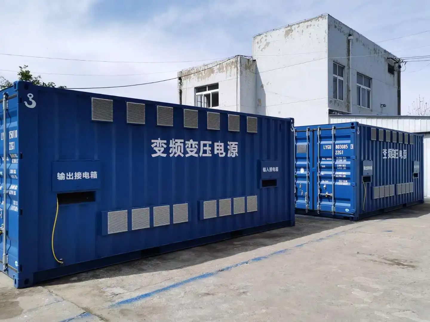
Before selecting air-conditioning units, first identify what is actually installed inside the enclosure.
- Frequency-converter cabinets
- Phase-shifting or isolation transformers
- High- and low-voltage switchgear
- Control cabinets
- Auxiliary power equipment
- Fans and other electrical auxiliaries
Each item contributes heat in a different way. Converter losses change with operating load. Transformer temperature also changes with loading and cooling conditions. Switchgear, conductors and auxiliary devices add further heat to the room.
The useful question is not “This is a 630 kVA shore power system. How many air conditioners do we need?” It is “Under the intended operating condition, how much heat remains inside the controlled enclosure?”
Two systems can have the same electrical rating and still require different cooling arrangements. A transformer placed inside the container changes the cooling duty. So does the number of converter cabinets, the operating mode and the amount of equipment running at the same time.
For fixed outdoor installations, our containerized shore power systems page shows how conversion equipment, transformers, switchgear and environmental-control equipment can be integrated into one package.
Cabinet Airflow Does Not Remove Heat From the Container
The referenced shore power design uses forced-air cooling inside the converter equipment.
Centrifugal fans are used for the power cabinets and transformer cabinets. The power-cabinet arrangement takes air from the front and rear and uses high-air-volume fans at the upper part of the cabinet. The power-unit airflow path is designed to be relatively short and wide.
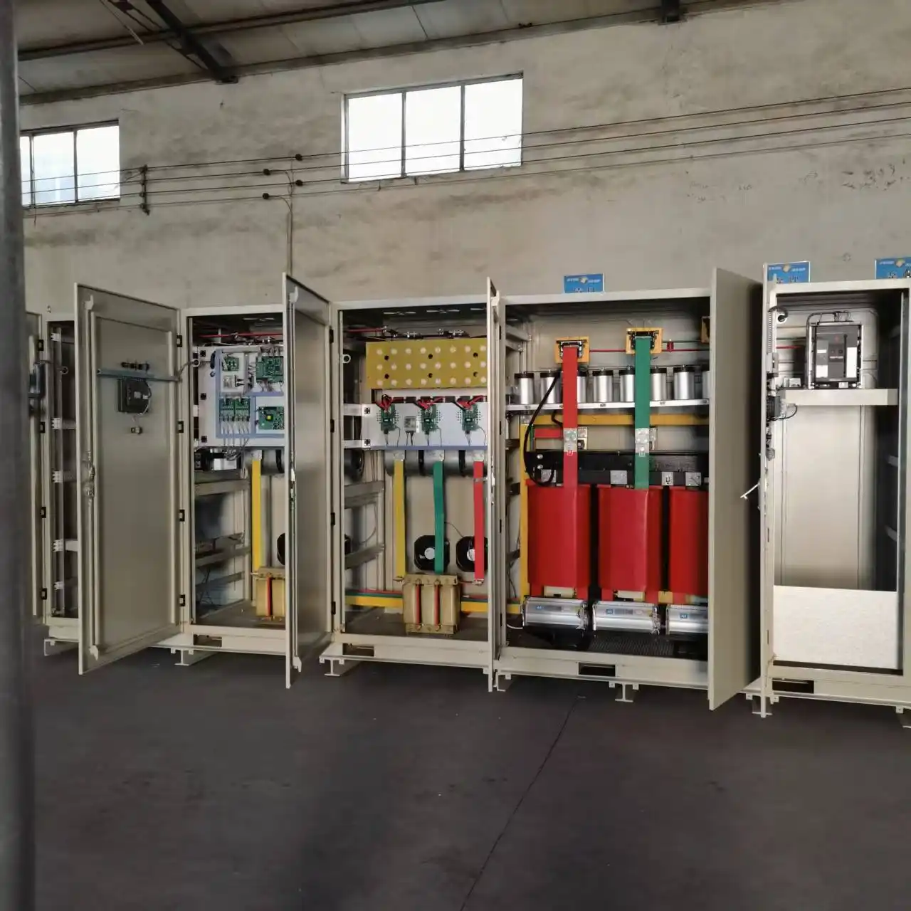
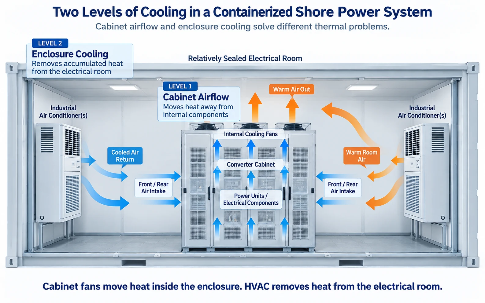
Internal airflow performs an important job. It moves heat away from the power units and other internal components.
But the heat has not disappeared.
If the warm air is discharged into an enclosed electrical room, the room cooling system still has to remove that heat.
A practical review asks three questions:
- How is heat removed from the component?
- Where does that heat go after it leaves the cabinet?
- How is it finally rejected outside the enclosure?
If the third question has no clear answer, adding more cabinet fans will not solve the thermal problem.
Why a Relatively Sealed Air-Conditioned Arrangement Can Be Useful
The cooling solution in the technical reference uses industrial air conditioning for applications where the external environment is relatively harsh or dusty.
Instead of continuously relying on outdoor air, the electrical room is kept relatively isolated from the outside environment. Warm air discharged by the electrical equipment is cooled by the air-conditioning system and returned to the equipment area.
This does not mean every containerized shore power system must use the same arrangement.
A more open ventilation scheme may suit some installations. A relatively sealed air-conditioned room may be more appropriate for others.
For coastal projects, humidity, airborne contamination and salt exposure should also be confirmed separately rather than assumed from the electrical rating.
A 630 kVA Example: Four Customized 5P Air-Conditioning Units
One 630 kVA project reference provides a useful example.
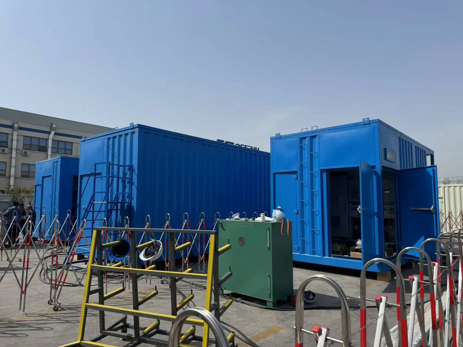
In that configuration, the electrical room contained the isolation transformer and other cabinets. The technical solution used four customized 5P industrial air-conditioning units for the enclosure cooling system.
This is useful project evidence, but it is not a sizing rule.
You should not conclude that every 630 kVA shore power system needs four 5P units.
Change the transformer arrangement, converter losses, enclosure dimensions, outdoor condition or operating duty, and the required HVAC capacity can change as well.
If someone gives you an HVAC quantity from shore power kVA alone, ask what heat-load and operating assumptions were used.
Cooling Reliability Starts Before the Air Conditioner
Cooling reliability is not simply a question of how many air-conditioning units are installed.
The internal cooling fans also need dependable power and fault monitoring.
In the referenced converter cooling design, the fans have two power-supply paths.
One comes from an external 380 V three-phase four-wire supply. The second is derived from the main power system through an internal transformer. The design allows transfer between the two sources without interrupting the fan supply.
The same technical solution defines the response to a cooling-system fault.
The converter does not immediately shut down at the first cooling alarm. It can continue operating while a local audible/visual alarm is generated, a warning is shown on the controller and the alarm is sent to the monitoring system.
If the problem is not corrected and the temperature reaches the configured upper limit, the converter shuts down.
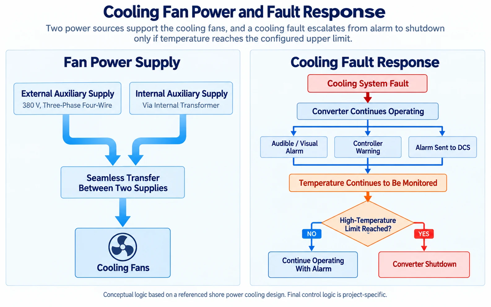
For a new project, you should define which cooling failures generate warnings, which temperatures are monitored, how long operation may continue, and what condition requires shutdown.
Do not assume that installing several air conditioners automatically creates N+1 cooling redundancy. The remaining cooling capacity after one unit is unavailable still has to be checked for the actual project.
Do Not Use One Room Temperature to Represent Every Component
The general container temperature is useful, but it does not tell you the complete thermal condition of the system.
The transformer is a good example.
In the referenced design, the transformers are equipped with cooling fans and temperature monitoring. Temperature sensors are installed in each low-voltage winding phase.
The temperature controller displays the three winding temperatures and provides high-temperature alarm and overtemperature-trip outputs. It also monitors temperature-sensor and fan faults.
A container may still appear to be within its normal air-temperature range while one transformer winding or another internal component is approaching its limit.
For this reason, temperature monitoring should follow the equipment that actually carries the thermal risk.
The wider relationship between the converter, transformer, switchgear, monitoring and protection can be seen on our shore power system architecture and components page.
Airflow Has to Be Considered During the Layout Stage
Cooling design is partly an electrical problem and partly a mechanical-layout problem.
A fan can only move air through the path available to it.
Cabinet position, air inlet clearance, exhaust direction and the location of the air-conditioning units all influence the result.
If warm discharge air returns directly to the equipment inlet, cooling performance suffers. If HVAC supply air reaches only one part of the room, one sensor may show a good temperature while another cabinet operates much hotter.
Maintenance also needs space. Fans, filters and air-conditioning components eventually need inspection or replacement.
- Air inlet clearance
- Warm-air discharge path
- HVAC supply and return position
- Transformer and cabinet clearance
- Temperature-sensor position
- Maintenance access
These points should be checked while the container arrangement is still flexible. Cooling is much harder to correct after the cabinets, transformer, cable routes and doors have already been fixed.
What Should Be Checked During Load Testing?
A no-load check tells you whether the fans and air conditioners can start.
It does not tell you how the enclosure behaves when the electrical equipment is producing normal operating heat.
The technical documentation contains more than one load-test procedure.
Factory Test Reference
- 30% rated load
- 60% rated load
- 100% rated load
- Run until temperature becomes stable
- Continue for another hour at full load
Separate Load-Test Reference
- Progressively increase to 100% load
- 100% load operation for 60 minutes
- Loading and unloading tests
- Continuous full-load data recording
- 20–30% load-change test
These are project test procedures, not universal acceptance criteria for every shore power system.
Cooling performance should be checked while the system is actually generating heat.
During the thermal review, useful observations include transformer temperatures, converter cooling status, fan operation, enclosure temperature and any high-temperature alarms.
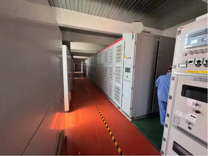
Factory testing and site testing answer different questions. A factory can verify the equipment, control logic and defined test condition. The final site adds the actual installation environment and final enclosure arrangement.
Our shore power manufacturing and FAT page explains how functional tests, protection checks and project-defined load testing fit into the delivery process.
What We Need Before Confirming the HVAC Arrangement
If you are asking us to review cooling for a containerized shore power system, do not send only the required kVA.
Send the actual operating conditions.
Electrical
- Rated capacity
- Input voltage and frequency
- Output voltage and frequency
- Converter configuration
- Expected continuous operating load
Equipment
- Transformer rating and location
- Equipment installed inside the enclosure
- Number of systems operating simultaneously
- Equipment-loss data if available
Site Conditions
- Maximum ambient temperature
- Humidity
- Dust or airborne contamination
- Coastal or salt exposure where applicable
Mechanical & Control
- Container or electrical-room dimensions
- Proposed equipment layout
- Preferred cooling arrangement
- Temperature and cooling alarms
- Required response to cooling failure
If an existing layout drawing is available, include it. That gives the HVAC review a real engineering basis.
The cooling arrangement can then be checked together with the electrical layout, airflow path, monitoring and maintenance access instead of being treated as a separate accessory.
Frequently Asked Questions
Can HVAC capacity be selected only from the shore power kVA?
No. The kVA rating describes electrical capacity, not the heat that remains inside the enclosure. Transformer location, converter losses, cabinet arrangement, operating duty and environmental conditions also affect the required cooling.
Are the fans inside the converter cabinet enough?
Not necessarily. Cabinet fans move heat away from internal components. If that heat is released into an enclosed electrical room, the HVAC or ventilation system still has to remove it from the enclosure.
Does every 630 kVA shore power system need four 5P air conditioners?
No. Four customized 5P units were used in one 630 kVA reference configuration. That is a project result, not a universal sizing rule.
If several air conditioners are installed, does that mean the cooling system is redundant?
Not automatically. You still need to calculate what happens when one unit is unavailable. The remaining capacity may support full load, reduced load or only enough time for a controlled shutdown. That has to be defined for the project.
Should transformer temperature be monitored separately from room temperature?
Yes. The referenced transformer design uses winding temperature sensors, temperature display, high-temperature alarm and overtemperature-trip signals. Transformer thermal condition cannot be judged from room temperature alone.
Can a no-load factory test prove that the HVAC capacity is sufficient?
No. A no-load test can confirm basic operation. Thermal performance is more meaningful when the electrical system is operating under load and producing heat.
Discuss Your Containerized Shore Power Cooling Requirement
Send us your system capacity, voltage and frequency, transformer arrangement, equipment layout, site temperature and humidity, and the proposed container dimensions.
If equipment-loss data or an existing layout drawing is available, send that as well.
We can review the internal airflow path, enclosure cooling method, HVAC capacity, cooling-failure response and temperature-monitoring points before the final container arrangement is fixed.
Send Your Project Data