
How a 10kV Shore Power System Converts to 400V/50Hz or 440V/60Hz
A port with a 10kV electrical supply cannot assume that a step-down transformer alone will produce power suitable for every vessel. The shore-power system must match the vessel’s voltage and frequency while also coordinating isolation, grounding, protection, load behavior and the ship-to-shore connection interface.
When a 10kV/50Hz port has to supply a vessel at 400V/50Hz, voltage transformation may be sufficient if the remaining electrical conditions are compatible. When the vessel requires 440V/60Hz, however, the system must convert both voltage and frequency before power reaches the ship.
Four Compatibility Checks Before Choosing the Power Path
The engineering question is not simply how to reduce 10kV to a lower voltage. The real question is how to make the available port supply electrically compatible with the vessel that will connect to it.
Before deciding whether a project needs only voltage transformation or a complete frequency-conversion system, four conditions should be checked together.
| Check | Engineering question | What it can change |
|---|---|---|
| Voltage | What voltage is available ashore, and what voltage does the vessel require? | Transformation ratio and equipment voltage class |
| Frequency | Does the port operate at 50Hz or 60Hz, and what does the vessel require? | Whether active frequency conversion is required |
| Interface | What are the grounding, neutral, protection and physical connection requirements? | The vessel-side electrical and connection architecture |
| Load | What is the maximum demand, largest motor, starting method and expected load step? | Converter, transformer and feeder sizing |
This avoids one of the most common mistakes in early shore-power planning: selecting equipment from voltage and nominal kVA alone.
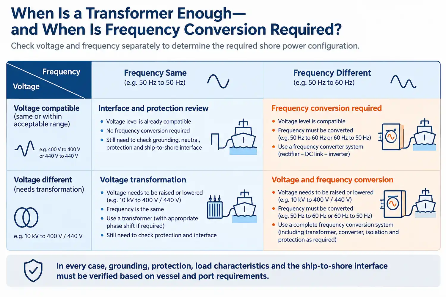
If voltage differs but frequency is already compatible, the project may mainly require voltage transformation together with the necessary isolation, protection and ship-to-shore interface. If both voltage and frequency differ, coordinated voltage and frequency conversion is required.
For a wider review of capacity, starting load, cable distance and vessel-interface inputs, see our shore power selection and compatibility guide .

When Is a Transformer Enough—and When Is Frequency Conversion Required?
A transformer changes voltage. It does not change frequency.
If a port has a 10kV/50Hz supply and the vessel requires 400V/50Hz, a transformer-based architecture may be technically possible if the remaining grounding, protection, short-circuit, isolation and connection requirements can also be satisfied.
Now consider a vessel requiring 440V/60Hz from the same 10kV/50Hz port grid.
This is why the first design decision should not be “which transformer size should we buy?” It should be: do the port and vessel already operate at compatible voltage and frequency conditions?
Where frequency conversion is required, the marine frequency converter becomes part of the complete shore-to-vessel conversion chain rather than a stand-alone cabinet.
Why Frequency Matters Even When the Voltage Looks Correct
A frequency difference is not simply a label on the vessel nameplate.
Many onboard auxiliary loads include induction motors driving pumps, ventilation systems, compressors and other machinery. Their operating characteristics depend on both voltage and frequency.
Supplying equipment designed around a 60Hz electrical system from an unsuitable 50Hz source can affect motor speed, magnetic conditions and connected-equipment performance.
The shore system therefore has to establish the required electrical conditions before the vessel is energized.
For a project intended to serve different vessel types, selectable operating modes such as 400V/50Hz and 440V/60Hz can provide useful flexibility. These modes must be engineered into the converter, transformer, protection and control system. They should not be treated as two HMI settings added after the power equipment has already been selected.
The Complete Power Path from a 10kV Port Grid to the Vessel
Each stage solves a different electrical or interface problem. The equipment should therefore be engineered as one coordinated system rather than purchased as isolated cabinets.
1. Medium-Voltage Incoming Switchgear
The incoming switchgear connects the shore-power system to the port distribution network.
Its role can include switching, isolation, current and voltage measurement, fault protection, breaker status, earthing-switch status and interlocking with upstream and downstream equipment.
The switchgear must be coordinated with the port electrical system rather than selected as an isolated component. Its fault rating also depends on the actual short-circuit conditions available from the port network.
2. Phase-Shifting Transformer
In a multilevel frequency-converter architecture, the transformer ahead of the converter can do more than provide a different voltage.
Multiple secondary windings can feed separate converter power cells with controlled phase relationships. This supports the converter topology and can help reduce unwanted input-side harmonic effects.
In one 630kVA shore-power project developed with project partners, the conversion section used a cascaded power-cell arrangement supplied through a phase-shifting transformer. This is a project-specific example rather than a universal rule for every shore-power converter.
3. Rectification, DC Link and IGBT Inversion
Inside the converter, the incoming AC power is converted into controlled electrical output through several power-electronic stages.
The purpose is not merely to change 50Hz into 60Hz. The converter also has to maintain the required output voltage and frequency while the connected vessel load changes.
This becomes important when pumps, fans, compressors or other large loads start and stop. A shore-power converter selected too close to average vessel consumption may appear adequate on a simple load calculation but perform poorly during large load steps or motor starting.
Maximum load, transient demand and the largest starting load should therefore be reviewed before the converter rating is finalized.
4. Output Isolation Transformer
After frequency conversion, an output transformer can provide galvanic separation and establish the required vessel-side voltage and interface arrangement.
In one 630kVA project configuration developed with project partners, the output transformer used a D,yn11 connection.
The vessel single-line diagram is therefore one of the most useful documents during engineering review.
5. Low-Voltage Protection and Metering
Producing the correct waveform is not the end of the conversion process.
Before the vessel can be supplied, the low-voltage output has to be protected, measured and controlled.
In one 630kVA project, the protection scope included phase loss, overvoltage, undervoltage, overload, overcurrent, phase imbalance, abnormal frequency and reverse-power protection. Output-side energy metering was also included.
This illustrates an important distinction: correct voltage and frequency do not by themselves create a complete shore connection.
6. Berth Connection Equipment
The final power interface includes more than the output breaker.
Depending on the installation, it may include berth connection boxes, plugs and sockets, shore cables, cable-management equipment, protective-earth conductors, pilot or permissive circuits, emergency-stop interfaces and communication links.
The electrical conversion system and physical connection system have to be treated as one operating chain. A correctly sized converter cannot compensate for an unsuitable or incorrectly coordinated ship-to-shore interface.
For the wider relationship between switchgear, transformers, converters, connection equipment and the vessel interface, see our shore power system architecture and components .
Does a 10kV Port Supply Automatically Mean High-Voltage Shore Connection?
A port may distribute power internally at 10kV, while the conversion system supplies the vessel through a 400V or 440V low-voltage connection.
This distinction matters because “10kV shore power” can refer to the port-side distribution voltage in one project and the actual vessel connection voltage in another.
IEC/IEEE 80005-3 addresses low-voltage shore connection systems within its defined scope and includes shore-side equipment, transformers, frequency converters, protection, control, monitoring and interlocking within the wider connection-system boundary.
For a broader explanation of LV/HV classification, applicable IEC/IEEE documents and project approval boundaries, see our shore power standards and compliance guide.
400V/50Hz vs 440V/60Hz: What Actually Changes?
A dual-mode shore-power system may be required to serve vessels with different electrical standards. The visible differences are voltage and frequency, but engineering review should go further than those two numbers.
| Design point | 400V / 50Hz | 440V / 60Hz |
|---|---|---|
| From a 10kV / 50Hz grid | Voltage transformation may be sufficient if all other electrical conditions are compatible | Frequency conversion is required in addition to voltage transformation |
| Motor / load review | Required | Required |
| Grounding and neutral review | Required | Required |
| Protection coordination | Required | Required |
| Cable and terminal-voltage review | Required | Required |
Two vessels that both use approximately 440V may still impose different system requirements because their load profile, grounding arrangement, connection method or operating procedure differs.
A 630kVA Shore-Power Configuration Serving Three Berth Positions
One 630kVA shore-power project provides a useful example of how these functions come together in a real system.
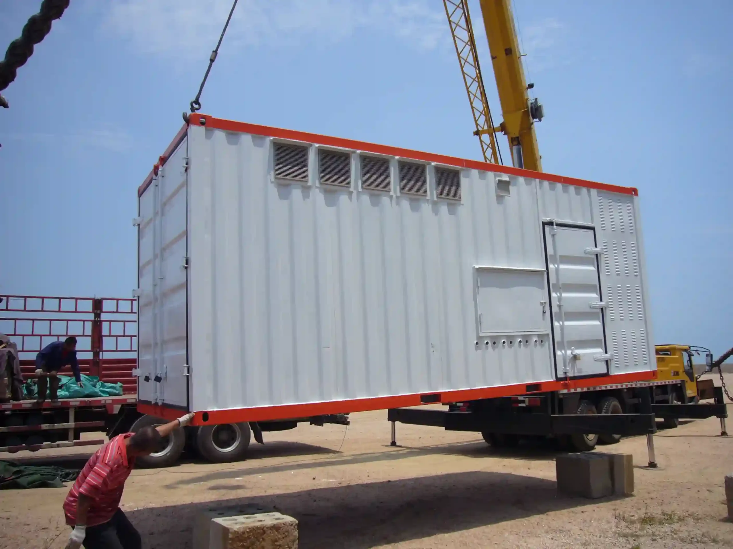
The project configuration included a 10kV port-side supply, medium-voltage equipment, a phase-shifting transformer, a 630kVA frequency-conversion section, a 630kVA dry-type isolation transformer, low-voltage distribution and three berth-side connection points.
The required vessel-side operating modes were 400V/50Hz and 440V/60Hz.
The converter configuration used IGBT-based power conversion and, in that specific project, a six-stage cascaded power-cell arrangement.
The project is useful because it shows that shore-power engineering is not defined by one piece of equipment. The converter, transformers, switchgear, protection, metering, berth connection and monitoring system work together as one power path.
Three Berth Connection Points Do Not Mean 3 × 630kVA Simultaneous Capacity
The same 630kVA project also illustrates an important planning distinction.
There were three berth-side output positions. That did not mean that three vessels could each receive 630kVA simultaneously.
Three different questions should therefore be kept separate:
- How many physical connection points are required?
- How many vessels may connect at the same time?
- How much conversion capacity must be available simultaneously?
If simultaneous vessel operation is required, the project may need a different converter capacity, transformer arrangement, feeder architecture, diversity strategy or redundancy concept.
Adding additional output breakers does not create additional conversion capacity.
Why the Voltage-Control Measurement Point Matters
The voltage displayed inside the converter is not necessarily identical to the voltage available at the vessel connection.
Between those two points are components such as the output transformer, low-voltage switchgear, feeder cables, shore cable and connection equipment. Their impedance produces voltage drop as current increases.
In one 630kVA project, the output-voltage closed loop used feedback from the isolation-transformer output side.
The broader engineering principle is more general: voltage should be evaluated at a point that meaningfully represents the connected load, not only at an internal converter node.
Some converter configurations can provide controlled voltage-drop compensation. That does not eliminate cable engineering. Conductor size, route length, current, thermal rating, fault duty and allowable vessel-terminal voltage still need to be checked for the actual installation.
What Can Go Wrong When the Power Path Is Selected Incorrectly?
A shore-power system may have the correct rated kVA and still be unsuitable for the vessel.
Correct Voltage, Wrong Frequency
A transformer reduces the voltage successfully, but the vessel requires a different frequency.
Result: the electrical interface remains incompatible.
Adequate Average Power, Insufficient Transient Capability
The converter is selected from normal operating consumption without checking large motor starting or load steps.
Result: excessive voltage disturbance or unwanted protection operation may occur during real vessel operation.
Multiple Outlets Interpreted as Simultaneous Capacity
Several berth boxes are installed, but the upstream conversion train was designed for one selected berth.
Result: the architecture cannot support the assumed simultaneous demand.
Converter Settings Correct, Connection Interface Wrong
Voltage and frequency are correct, but grounding, protection, pilot logic or the physical shore connection does not match the vessel.
Result: the vessel may still be unable to connect safely.
Voltage Regulated at the Wrong Point
The converter maintains its internal output target while the downstream cable path creates excessive voltage drop.
Result: the actual vessel-terminal voltage may fall outside the intended operating range.
Monitoring Helps Determine Where a Problem Started
A complete shore-power system also needs visibility across the conversion chain.
Useful monitoring points can include input voltage and current, converter status, output voltage and current, frequency, transformer temperature, breaker position, alarms, trips, power, energy and selected waveform or trend data.
In one 630kVA project, the monitoring requirements included output voltage, output current and necessary waveform information so that abnormal interruptions could later be reconstructed and analysed.
This becomes important when a vessel supply is interrupted. Without coordinated event and operating records, it can be difficult to determine whether the disturbance began in the port grid, converter, output distribution, berth interface or on the vessel.
Monitoring is therefore part of engineering verification and fault diagnosis, not merely an operator-display function.
How Engineers Verify Compatibility Before Production
A shore-power proposal should not be finalized from a requested voltage and kVA value alone.
Engineering review normally begins with the port network and vessel electrical data and follows the complete path between them.
| Project input | Why it matters |
|---|---|
| Port voltage and frequency | Defines the starting electrical condition and conversion requirement |
| Available short-circuit level | Influences switchgear and protection duties |
| Vessel voltage and frequency | Defines the required final electrical condition |
| Vessel single-line diagram | Supports grounding, neutral, protection and interface review |
| Maximum operating load | Defines the base conversion-capacity requirement |
| Largest motor / starting method | Defines transient and overload requirements |
| Expected load steps | Affects dynamic voltage and frequency performance |
| Number of berth connections | Defines distribution arrangement |
| Simultaneous vessels | Defines aggregate conversion capacity |
| Cable distance and route | Affects voltage drop, conductor size and thermal design |
| Connection equipment | Defines the physical and electrical ship-to-shore interface |
| Metering requirement | Defines the commercial energy-measurement boundary |
| Monitoring / communication requirement | Defines PLC, SCADA and system-interface scope |
| Applicable standard / class requirement | Defines final design and acceptance boundaries |
This review may change the architecture before equipment production starts. That is preferable to discovering an interface mismatch after the system reaches the berth.
The agreed design should then be verified through the appropriate production, inspection and commissioning process. See our shore power manufacturing and FAT guide for the relationship between factory checks, load testing, SAT and first vessel connection.
What Should Be Included in a Shore Power RFQ?
A useful RFQ does not need to contain a complete electrical design, but it should provide enough information to define the project boundary.
Port-Side Information
- Available voltage
- Frequency
- Short-circuit data if available
Vessel Information
- Required voltage and frequency
- Maximum load
- Largest starting load
- Single-line diagram if available
Berth and Connection Information
- Number of connection positions
- Number of vessels that must be supplied simultaneously
- Approximate cable distance
- Preferred connection arrangement
Control and Project Requirements
- Local or remote operation
- Monitoring and event recording
- Metering
- Communication
- Required transfer method
- Applicable standards or class requirements
Without these inputs, nominal equipment can be quoted, but the complete shore-to-ship power path cannot be defined reliably.
Frequently Asked Questions
Can a transformer convert 10kV/50Hz into 440V/60Hz?
No. A transformer can change the voltage from 10kV to a lower value, but the output frequency remains tied to the input frequency. If a 50Hz port has to supply a 60Hz vessel, a frequency-conversion stage is required.
Can one shore-power system provide both 400V/50Hz and 440V/60Hz?
Yes, if the converter, transformer, protection and control architecture is designed for both operating modes. The actual arrangement should be confirmed from the intended vessel types and their electrical requirements.
Does a 10kV shore supply mean the vessel must connect at 10kV?
No. The port may distribute electricity at 10kV and then convert it to a low-voltage vessel-side connection such as 400V or 440V. Port distribution voltage and shore-to-ship connection voltage should be treated separately.
Why is an isolation transformer used after the converter?
It can provide galvanic separation and form part of the required voltage, neutral and grounding interface between the shore system and vessel. The transformer connection and grounding arrangement should be selected from the actual project rather than copied from another installation.
Can a 630kVA system serve three berths?
It can be arranged to serve three physical berth connection positions. That does not automatically mean three vessels can each receive 630kVA at the same time. Simultaneous operation must be supported by the total conversion and distribution capacity.
How should shore-power capacity be selected?
Start with maximum operating load, but also review the largest starting load, expected load steps, transformer and cable characteristics, operating margin and future requirements. Average energy consumption alone is not sufficient for converter sizing.
Does a long shore cable affect the vessel voltage?
Yes. Cable resistance and reactance create voltage drop under load. Some systems can use controlled compensation, but cable length, conductor size, current, thermal duty and permitted vessel-terminal voltage still have to be checked.
Can the vessel transfer from onboard generation to shore power without interruption?
Potentially, but this should not be assumed as a standard capability. A no-break or parallel transfer requires compatible shipboard equipment, synchronization conditions, protection logic, control signals and an approved operating sequence. It should be confirmed from the actual vessel and shore-system design.
Technical References
The project examples in this article are used as engineering evidence and should not be interpreted as universal configurations. International shore-connection standards define the wider design, interface and verification boundaries.
- IEC/IEEE 80005-3:2025 — Utility connections in port — Part 3: Low-voltage shore connection systems — General requirements. IEC reference
- IEC/IEEE 80005-2:2016 — Utility connections in port — Data communication for monitoring and control. IEEE reference
Review Your Shore-to-Vessel Power Path
Send the available port voltage and frequency, vessel voltage and frequency, expected load, berth arrangement, cable distance and vessel single-line diagram if available.
SDACME can review whether the project requires voltage transformation, frequency conversion or a combined shore-power architecture before individual equipment is finalized.
Send Project Requirements