Containerized vs Mobile Shore Power Systems: How to Choose

Engineering Guide

A containerized shore power system and a mobile shore power system can contain many of the same electrical components. They are not the same installation.

A fixed containerized system is assembled inside an engineered enclosure and connected to one defined operating location. A mobile system is designed to move between planned service points. That additional requirement affects the chassis, cable handling, grounding, cooling, interlocks and the checks completed before the equipment is energized again.

The selection should therefore begin with the operating plan, not the container size. If the system will remain beside one berth or in one shipyard area, a fixed containerized package is usually more straightforward. If one power package must serve different berths, docks or maintenance positions, the movement and reconnection process has to be part of the design from the beginning.

Fixed containerized system: one defined installation position
Mobile system: planned movement between defined service positions

Containerized Does Not Automatically Mean Mobile

Containerization describes how the electrical equipment is packaged. Mobility describes how the equipment will be operated after delivery.

A container can simplify factory assembly, protect equipment outdoors and provide a defined footprint for the converter, transformers, switchgear, control system and HVAC. It can also be transported to the project site as one integrated package. None of those features, by themselves, mean that the system is suitable for frequent relocation.

A standard containerized system may be lifted once, placed on a foundation and connected with permanent incoming and outgoing cables. Moving it later may require a crane, cable termination work, civil preparation and a new commissioning process. It is transportable, but movement is not part of normal operation.

A mobile shore power system is different. The project team expects the equipment to change position during its working life. The route, ground loading, connection points and operating sequence must therefore be repeatable. A wheeled chassis or skid can support movement, but the mechanical carrier is only one part of the solution.

For available fixed outdoor configurations, see our containerized shore power systems page.

How a Fixed Containerized Shore Power System Is Installed

A fixed containerized system is normally selected when the equipment has one defined operating position and the project benefits from completing more integration work before shipment.

The enclosure can house the frequency converter, transformers, medium- or low-voltage switchgear, protection relays, metering, PLC, HMI and environmental-control equipment. The exact equipment list depends on the shore grid, vessel connection and agreed supply scope.

Factory integration reduces the amount of internal cabinet work required at site, but it does not remove the external interfaces. The container still needs an incoming shore supply, an outgoing connection to the berth or vessel, a protective earthing arrangement, control and communication links, drainage, HVAC clearances and maintenance access.

The foundation and cable entries are usually prepared for one location. Cable lengths, conductor sizes and protection settings can then be coordinated around a stable layout. Once the system is commissioned, the external connections normally remain in place.

This arrangement is well suited to ports or shipyards that need outdoor equipment but do not have a dedicated electrical room. It also provides a practical route when the customer wants assembly, internal wiring and project-specific testing completed before delivery.

A fixed containerized installation normally has:

  • One defined equipment position
  • A permanent or long-term foundation and cable route
  • Site-specific input, output, earthing and control interfaces
  • HVAC and corrosion protection selected for the local environment
  • A planned installation, SAT and commissioning sequence

What Makes a Shore Power System Mobile

A mobile system must remain safe and practical each time it changes position. That requirement reaches well beyond adding wheels under a container.

The mechanical design has to consider total mass, center of gravity, wheel or support loads, towing or self-propelled movement, braking, slopes, turning space and the condition of the route. Equipment inside the enclosure must withstand the loads created during repeated movement, not only the transport from the factory to the first site.

The electrical interfaces also change. Permanent terminations may be acceptable for a fixed installation, while a mobile system needs a controlled method for disconnecting and reconnecting the incoming supply, vessel feeder, earthing conductor, pilot circuits and communication links. Connector ratings and interlocks must match the maximum voltage, current and fault conditions of the system.

Cable handling often becomes the limiting practical issue. A 500 kVA power package may be easy to place on a mobile chassis, but the required cables can still be heavy and difficult to move. The route, bending radius, storage method and safe handling process need to be reviewed with the equipment design.

Cooling must be checked at every planned operating position. Air inlets, exhaust paths and condenser clearances cannot be blocked by a wall, stacked materials or another piece of equipment. The operator also needs enough space to inspect switchgear, replace converter modules and service the HVAC system.

Mobility adds five project questions:

  • How will the package move, and how often?
  • Where are the approved operating positions?
  • How will power, earth, control and communication connections be repeated?
  • How will cables be handled and stored?
  • Which inspections and electrical checks are required after relocation?

Fixed Containerized vs Mobile Shore Power

The electrical rating alone does not decide between the two arrangements. Two systems with the same kVA, input voltage and output voltage can require very different mechanical and site designs.

The comparison below focuses on the operating conditions that normally change the project scope.

Decision factorFixed containerized systemMobile system
Normal operating locationOne defined positionSeveral planned service positions
Movement frequencyDelivery and exceptional relocationRelocation forms part of normal operation
Mechanical arrangementFoundation, lifting points and installation accessChassis or skid, route, ground loading, restraint and repeated movement duty
Power connectionsPermanent or long-term terminations may be usedRepeatable input, output, earth, pilot and control connections
Cable handlingStable cable route can be installedCable movement, storage, bending radius and safe handling must be planned
Cooling and accessClearances designed for one locationEvery approved position must provide airflow and maintenance access
Return to serviceSAT and commissioning after installationDefined checks after each relocation
Typical fitLong-term outdoor port or shipyard installationShared service positions, temporary work or changing berth demand

The Electrical Design Still Comes First

Mobility changes the installation, but it does not replace the normal shore power engineering process. The system still has to match the port or shipyard supply to the vessel load.

Start with the available input voltage and frequency. Then confirm the required vessel voltage, frequency, maximum load, power factor, largest motor, starting method and expected load steps. These values determine whether the system needs frequency conversion, voltage transformation, low- or high-voltage switching and a particular output distribution arrangement.

A mobile package may serve several connection points, but the number of outlets does not define the available capacity. If a 500 kVA unit has connections at two berths, it can provide a total of 500 kVA within the approved operating arrangement. It does not become two independent 500 kVA supplies.

The same distinction applies to simultaneous operation. Serving one vessel at a time from several possible positions is different from supplying several vessels together. If simultaneous demand is required, the converter capacity, transformer rating, feeder arrangement and protection coordination must be calculated for that duty.

Grounding and neutral treatment also need early attention. Each operating position must provide the required protective earth and equipotential connection. The output transformer vector group, neutral arrangement and earth-fault protection should be reviewed with the vessel single-line diagram rather than selected from a generic mobile-system specification.

Our shore power selection and compatibility guide lists the electrical information needed before the system architecture is confirmed.

Fixed 400 kVA Containerized Shore Power Project in Singapore
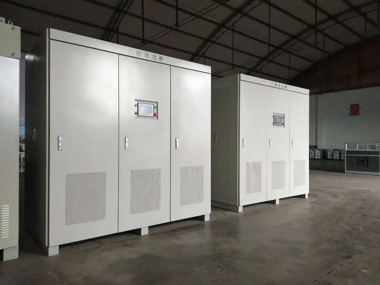
Singapore 400 kVA outdoor containerized shore power system

Singapore shipyard project: 400 kVA, 415 V / 50 Hz input and 415 V / 60 Hz output.

A shipyard project in Singapore provides a practical example of a fixed outdoor containerized arrangement.

The shore-side input was 415 V at 50 Hz. The required output was 415 V at 60 Hz, so the system needed controlled frequency conversion while maintaining the same nominal voltage level. The rated system capacity was 400 kVA.

The electrical equipment was assembled and internally wired inside an outdoor containerized enclosure. Testing was completed before shipment. The package was then delivered, commissioned, accepted and placed into operation at the shipyard.

Capacity400 kVA
InstallationFixed outdoor containerized
Input415 V / 50 Hz
Output415 V / 60 Hz

This project shows why containerized integration can be useful even at a moderate power rating. The reason was not simply the 400 kVA capacity. The customer needed an outdoor installation, defined equipment package and 50 Hz to 60 Hz conversion for the vessel application.

The equipment was installed for a defined project location. Its containerized construction simplified integration and environmental protection; routine relocation was not part of the operating requirement.

The confirmed electrical configuration and project status are shown in the full Singapore 400 kVA containerized shore power project case study.

A 500 kVA Mobile Arrangement for Two Adjacent Berths

A different project requirement involved two adjacent berth positions and a 500 kVA mobile transformer package. Instead of installing a separate complete package at each berth, the arrangement allowed one unit to be positioned near the connection point required by the operating schedule.

The proposed equipment included incoming ring-main switchgear, low-voltage output switchgear, a 500 kVA isolation transformer, an electrically driven chassis, berth-side connection boxes and ventilation equipment.

The shore supplies available at the berth positions included 6 kV at 50 Hz or 6.6 kV at 60 Hz. The vessel-side requirements included 400 V at 50 Hz and 440 V at 60 Hz. The operating mode and connection path therefore had to be confirmed before energization.

The mobile chassis solved the positioning requirement, but the complete operating process still depended on suitable connection points, cable routes, earthing, isolation and verification. Moving the package did not eliminate those engineering steps. It made them repeatable.

01 · ISOLATEDisconnect and verify the package is safe to move.
02 · MOVEUse the approved route and movement method.
03 · CONNECTComplete power, earth, pilot and control interfaces.
04 · VERIFYCheck the installation before energization.

This is the main commercial reason to consider a mobile arrangement: one power package can support changing service positions when the operating schedule does not require every berth to have an independent system at the same time.

The benefit has to be balanced against the additional mechanical design, cable handling and operating discipline. If the unit will rarely move, a fixed containerized system may be simpler to install and maintain.

Common Errors When Selecting the Installation Type

The wrong choice usually begins when the project is described only by capacity and container size. Several practical questions are then left until installation.

Every container is treated as mobile.

A container may be transportable for delivery without being designed for repeated movement, quick reconnection or operation from several positions.

The chassis is selected before the electrical system.

The transformer, converter, switchgear, cooling equipment and cable interfaces determine the mass, layout and access requirements of the mobile package.

Cable handling is excluded from the comparison.

Long low-voltage cables can be heavy, create voltage drop and require a defined storage and handling method.

Several connection points are mistaken for simultaneous capacity.

The number of available berth outlets and the number of vessels that can operate together are different design inputs.

Grounding is checked only during commissioning.

Each operating position needs a compatible earth and equipotential-bonding arrangement before the transformer and protection scheme are finalized.

Relocation is assumed to require no verification.

Connections, phase sequence, insulation condition, earthing, interlocks and cooling clearances should be checked before the system returns to service.

Most of these issues are inexpensive to solve during engineering. They become operational delays when they are first discovered beside the berth.

Information Needed Before Configuration

A useful inquiry should describe both the electrical requirement and the way the equipment will be used. A request for “one 500 kVA mobile container” is not enough to select the system.

If a site layout and vessel single-line diagram are available, include them. The two documents often answer questions about cable distance, operating positions, voltage class, grounding and distribution that cannot be resolved from a data sheet alone.

For shipyard and dry-dock operating conditions, see our shipyard shore power systems page.

Please provide:

  • Shore-side input voltage, frequency and available capacity
  • Vessel-side voltage, frequency and maximum load
  • Largest motor, starting method and expected load changes
  • Low-voltage or high-voltage vessel connection
  • Number and location of berth or work-area connection points
  • Number of vessels supplied at the same time
  • Fixed installation, occasional relocation or routine movement
  • Movement distance, route, slopes and ground conditions
  • Preferred towing, self-propelled, lifting or skid arrangement
  • Cable lengths, connector type and cable-management method
  • Earthing, pilot circuit and interlock requirements
  • Ambient temperature, humidity, salt-fog and corrosion conditions
  • Local and remote monitoring or communication requirements
  • Applicable standards, classification and testing requirements

Frequently Asked Questions

Is a containerized shore power system automatically mobile?

No. Containerized describes the enclosure and integration method. A mobile system must also be designed for its intended movement, repeated connections and operating checks.

Can a fixed containerized system be moved later?

It may be possible, but the relocation should be treated as an engineering change. Confirm lifting or transport loads, foundation, cable routes, grounding, cooling, protection settings and recommissioning requirements at the new location.

When should a mobile shore power system be considered?

Consider it when one package needs to serve several planned berth or shipyard positions and the operating schedule does not require an independent system at every position.

Does mobility determine whether the system is low voltage or high voltage?

No. The voltage architecture depends on the shore grid, vessel connection, load, current, cable route and overall electrical design. Either installation type can be configured around a low- or high-voltage system.

Can one 500 kVA mobile unit serve two berths?

Yes, when the distribution and operating sequence are designed for one 500 kVA package to serve the selected position. It does not mean that both berths can each receive 500 kVA simultaneously.

What must be checked after the unit is moved?

The project procedure may include visual inspection, cable and connector checks, protective earth verification, phase sequence, insulation condition, interlocks, cooling clearances, control communication and a controlled energization sequence.

Can factory acceptance testing be completed before shipment?

Yes. The agreed FAT can verify internal wiring, output voltage and frequency, load operation, protection, interlocks, HMI and communication functions. Site interfaces still require SAT and commissioning after installation.

What should be included in an RFQ?

Provide the electrical input and output, required capacity, load information, operating positions, movement frequency, cable and connection method, environmental conditions and the required supply scope.

Discuss Your Shore Power Installation Plan

If you are comparing a fixed containerized package with a mobile system, send us the shore-side input, vessel-side output, required capacity, operating positions and expected movement frequency.

We can review the electrical path, enclosure arrangement, connection method, cooling, cable handling and project supply boundary together.
