915 MHz HIGH-POWER MICROWAVE GENERATOR SERIES

915 MHz High-Power Microwave Generators

SDACME supplies magnetron-based continuous-wave 915 MHz microwave generator systems for high-power industrial equipment, OEM integration and project-based process systems.

Current published model routes include 25 kW, 75 kW and 100 kW, with a 30 kW project-configured option available after technical review. Power selection should be evaluated together with the application, waveguide interface, reflected-power conditions, cooling, site electrical supply, controls and destination country.
25 kW Published Model
30 kW Project Configured
75 kW Published Model
100 kW Published Model
✓ Continuous-wave magnetron architecture
✓ Water-cooled high-power configurations
✓ BJ9 interface on current published high-power models
✓ OEM, retrofit and project integration support
915 MHz High-Power Microwave System
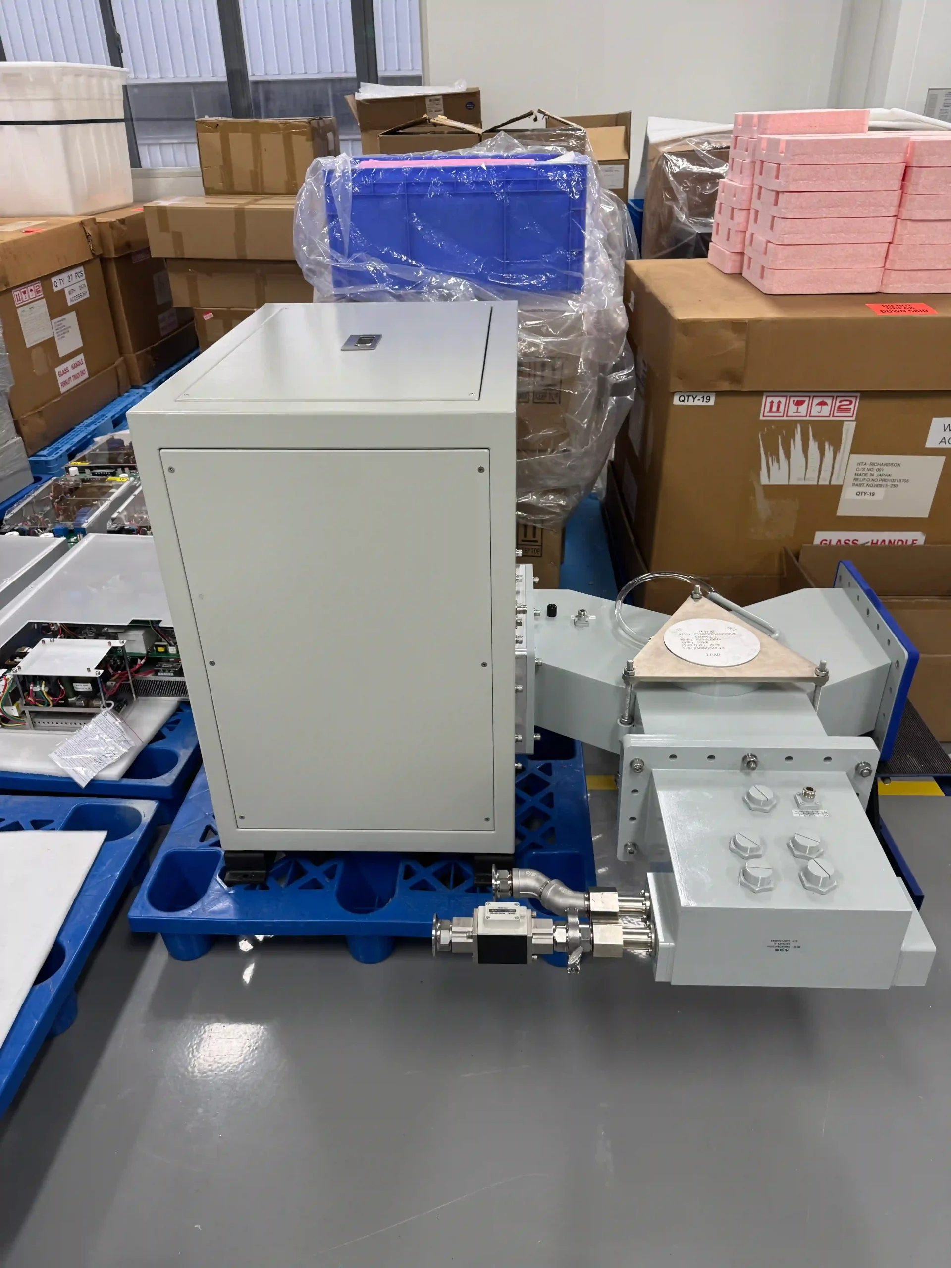
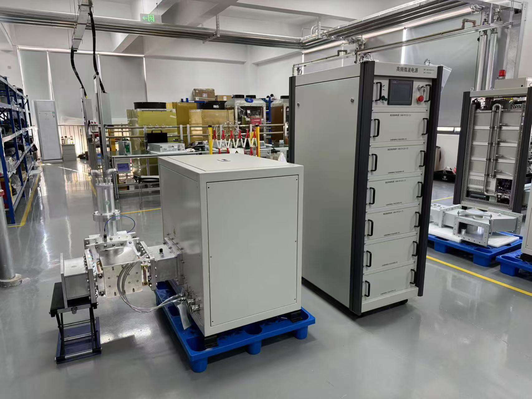
75 kW 915 MHz high-power industrial microwave generator system with power cabinet and microwave head
915 MHz SERIES OVERVIEW

What Is a 915 MHz Microwave Generator?

A 915 MHz microwave generator converts electrical input power into controlled high-power microwave energy for delivery into an applicator, process chamber or other engineered load. SDACME’s current 915 MHz range uses continuous-wave magnetron technology for high-power industrial equipment, OEM integration and project-based systems.
75 kW 915 MHz high-power microwave head side-front view
915 MHz High-Power Microwave Head
915 MHz Family Example 75 kW High-Power Configuration
915 MHz
HIGH-POWER SOURCE PLATFORM

Built for Project-Level Microwave Integration

At high microwave power, the source should be evaluated as part of the complete equipment rather than selected from rated kW alone.

Microwave power, waveguide routing, reflected-power conditions, cooling capacity, site electrical supply and control interfaces should be reviewed together before the final configuration is confirmed.

CW

Continuous-Wave Operation

Magnetron-based high-power microwave source architecture.

kW

25–100 kW Product Routes

25 kW, 75 kW and 100 kW available model routes, plus a 30 kW project configuration.

OEM

System-Level Engineering

RF, electrical, cooling and control interfaces are evaluated together.

TYPICAL SYSTEM LAYERS

From Site Power to the Process Load

The exact supply scope depends on the selected model, RF arrangement and project requirements.

01
AC

Power & Control

Electrical conversion, high-voltage supply, operating control and protection functions.

02
MW

Microwave Head

Magnetron and microwave-generating structure produce the high-power RF output.

03
RF

RF Delivery Path

Isolation, reflected-power handling, monitoring and waveguide components as required.

04
LOAD

Applicator / Load

Customer or project equipment connected at the agreed microwave interface.

DESTINATION-COUNTRY REVIEW

Confirm 915 MHz Suitability Before Final Selection

Frequency allocation and equipment requirements vary by region. The destination country and intended application should therefore be confirmed before a 915 MHz system configuration is finalized.

Send Project Details
NEXT: MODEL COMPARISON Compare the 25 kW, 30 kW, 75 kW and 100 kW routes.
Compare Power Options
HIGH-POWER MODEL SELECTION

Compare 25 kW, 30 kW, 75 kW and 100 kW

Use rated power as the first screening point, then confirm the complete 915 MHz configuration from the load, waveguide interface, reflected-power conditions, cooling system, site electrical supply and control requirements.

Start with the power class, then verify the interfaces.

Exact output range, frequency tolerance, dimensions, cooling requirements and communication functions are confirmed for the selected model or project configuration.

Available Model 915 MHz
25 kW

25 kW 915 MHz Microwave Generator

25 kW 915 MHz high-power microwave generator head and power cabinet
25 kW high-power generator configuration

A 25 kW rated-power route for industrial equipment, OEM integration and project systems requiring a lower power class within the 915 MHz high-power family.

Confirm for your project
  • Waveguide and flange interface
  • Cooling-water requirements
  • Control and communication interface
  • Site electrical and installation conditions
View 25 kW Model
Project Configuration 915 MHz
30 kW

30 kW Project Configuration

30 kW
Configured Around Your Equipment

RF, electrical, cooling, mechanical and control details are defined during technical review.

A 30 kW 915 MHz option can be evaluated when the project requires this power class and the final configuration is defined from the actual equipment and site conditions.

Send us
  • Application and target microwave power
  • Load, chamber or applicator information
  • Waveguide / flange requirements
  • Cooling, controls and site-power data
Ask About 30 kW
Available Model 915 MHz
100 kW

100 kW 915 MHz Microwave Generator

100 kW

High-Power Project Integration

A 100 kW rated-power route for high-power systems where site utilities, RF integration, cooling and installation conditions require detailed review.

Confirm for your project
  • Available electrical capacity
  • Cooling-system capacity
  • Waveguide and RF arrangement
  • Controls, protection and installation scope
View 100 kW Model
BEFORE MODEL SELECTION

Four Questions Help Narrow the Power Route

Full Selection Guide
01

What Microwave Power Is Required?

Provide the target power or rated power of the existing microwave source.

02

What Receives the Microwave Energy?

Describe the load, applicator, chamber, process system or existing equipment.

03

How Will the RF System Connect?

Provide the BJ9 / waveguide arrangement, flange orientation and existing RF components.

04

Can the Site Support This Power Level?

Electrical capacity and cooling conditions should be confirmed before final configuration.

NEXT: POWER SELECTION Select the right 915 MHz configuration for your equipment.
Power Selection Guide
ENGINEERING POWER SELECTION

How to Choose the Right 915 MHz Power Level

Choosing between 25 kW, a 30 kW project configuration, 75 kW and 100 kW requires more than comparing rated power. The microwave source should match the equipment, load, RF path, cooling system, electrical supply and control architecture as a complete system.

FIRST SELECTION RULE

Rated kW Is a Starting Point — Not the Final Specification

A higher-power microwave generator is not automatically the correct choice. Final selection depends on how the microwave energy is generated, delivered, coupled into the load and managed during actual equipment operation.

8-POINT TECHNICAL REVIEW

What Should Be Confirmed Before Selecting the Power Class?

These inputs allow the first technical review to move beyond a simple frequency-and-kW comparison.

01
FREQUENCY

Confirm the 915 MHz Design Basis

Confirm that the equipment or project is intended for the 915 MHz family and provide the destination country for regional suitability review.

Provide: Frequency requirement + destination country
02
POWER

Define the Target Microwave Power

Use the existing generator rating, equipment design, applicator requirement or project power target to establish the initial power class.

Provide: Existing or target microwave kW
03
LOAD

Describe the Load or Process Equipment

Explain what receives the microwave energy and whether the system operates in batch, continuous or another equipment-specific operating mode.

Provide: Load / chamber / applicator / equipment description
04
RF PATH

Confirm the Waveguide Interface

Review the BJ9 / waveguide route, flange geometry, orientation, transitions and available installation space before the microwave source is finalized.

Provide: Drawings, dimensions or interface photos
05
REFLECTION

Review Reflected-Power Conditions

The RF path and load should be reviewed for reflected power and for any project requirement involving isolation, monitoring, tuning or water-load components.

Provide: Existing RF arrangement or expected load behavior
06
CONTROL

Define the Control Interface

Identify the required local operation, remote start/stop, PLC communication, interlocks and equipment-level control functions.

Provide: Local / remote / communication / I/O requirements
07
COOLING

Confirm Cooling Capacity

Current published high-power configurations use water cooling. The available chiller or plant cooling conditions should be reviewed for the selected model.

Provide: Chiller / water-system information
08
SITE POWER

Check Site Electrical Capacity

Confirm the available input voltage, frequency, electrical capacity, protection and grounding before the final high-power configuration is selected.

Provide: Site voltage + frequency + available capacity
PRACTICAL SELECTION FLOW

From Application Requirement to Generator Configuration

01
Application Equipment + load
02
Target Power Initial kW class
03
RF Interface BJ9 / waveguide
04
Utilities Power + cooling
✓
Configuration 25 / 30 / 75 / 100 kW
POWER-ROUTE SCREENING

Use the Power Class to Start the Discussion

These routes are for preliminary screening only. Final configuration remains dependent on the complete project requirements.

25 kW

Published Model Route

Start here when the equipment design or existing system points to the 25 kW rated-power class.

View 25 kW →
30 kW

Project Configuration

Use this route when the project requires approximately this power class and the configuration needs engineering review.

Discuss 30 kW →
100 kW

High-Power Published Model

Start here when the equipment or project design requires the 100 kW rated-power class.

View 100 kW →
FASTER TECHNICAL REVIEW

What Should You Send for Initial Model Selection?

A useful first inquiry does not require a complete engineering specification. Start with the information already available from your machine or project.

01 Application / equipment type
02 Target or existing power
03 Destination country
04 Load / chamber / applicator
05 BJ9 / waveguide information
06 Site electrical supply
07 Cooling conditions
08 Control / communication needs
NOT SURE WHICH POWER CLASS TO USE?

Send Your Equipment Data for Technical Screening

We can review the initial 25 kW, 30 kW project, 75 kW or 100 kW route from your application, interfaces and site conditions.

Request Model Selection
NEXT: SYSTEM ARCHITECTURE Understand what is included in a high-power microwave system.
View System Architecture
SYSTEM ARCHITECTURE & SUPPLY SCOPE

What Is Included in a 915 MHz Microwave Generator System?

A high-power microwave source is more than a rated-kW power cabinet. The complete installation typically combines electrical power conversion, microwave generation, RF delivery, reflected-power management, control, cooling and the customer’s process equipment.

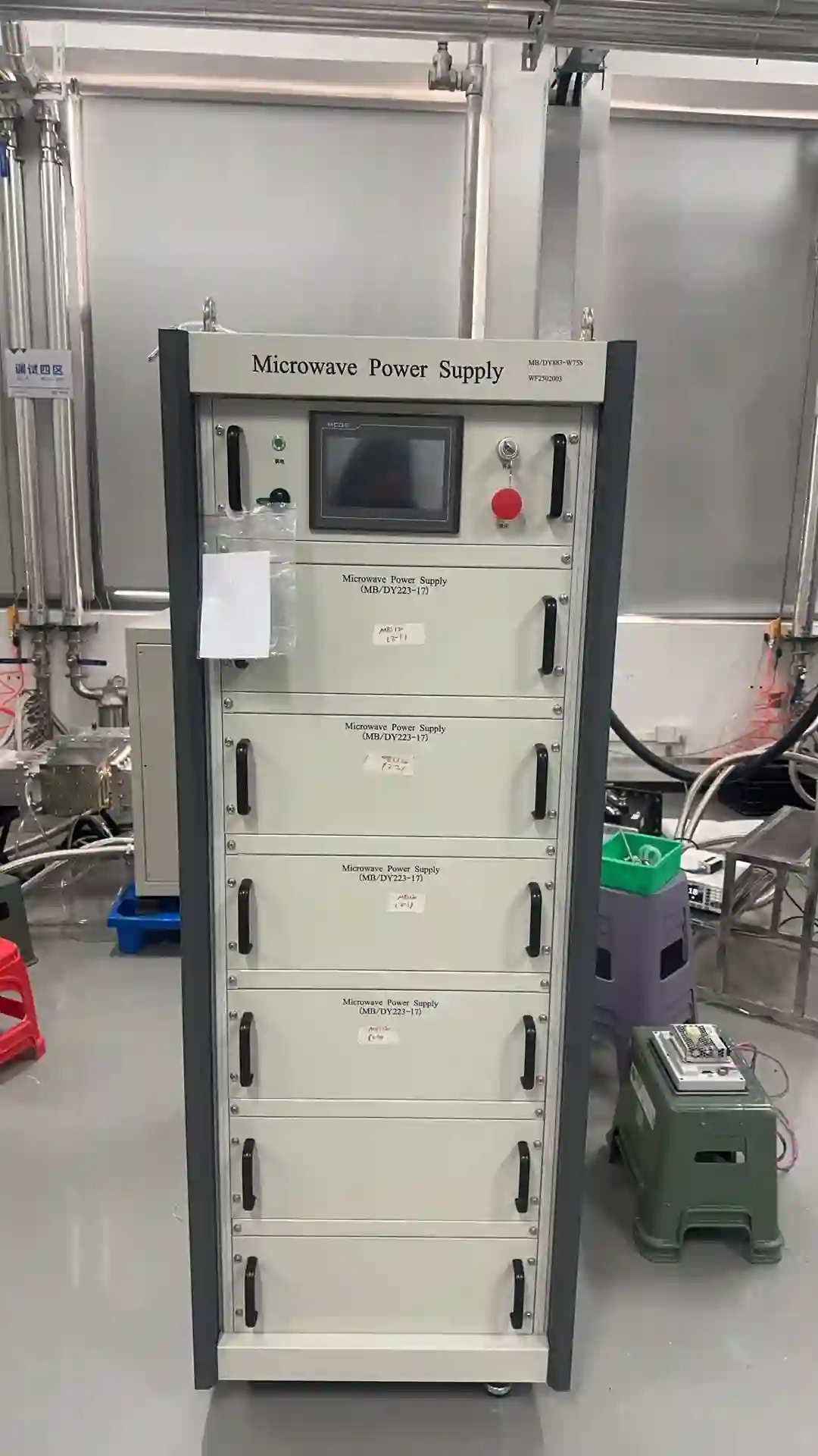
75 kW 915 MHz high-power microwave generator power cabinet front view
High-Power Microwave Power & Control Cabinet
System Component Example 75 kW Power Cabinet
915 MHz
GENERATOR PACKAGE

Power Cabinet and Microwave Head Form the Core Source

The core microwave-generator package normally combines the electrical power and control section with the microwave-generating head and the required interconnections between them.

The RF path beyond the microwave head is then configured around the selected model, process equipment and project requirements. Waveguide routing, reflected-power handling and auxiliary RF components therefore need to be confirmed rather than assumed from frequency and rated power alone.

01
Power & Control Cabinet

Electrical power conversion, operating control, monitoring and protection functions.

02
Microwave Head

Magnetron-based source assembly that generates the 915 MHz microwave output.

03
Electrical & Control Connections

Required connections between the cabinet, microwave head and agreed equipment interfaces.

TYPICAL ENERGY & CONTROL PATH

High-Power Microwave System Architecture

The final RF component list and interface arrangement are defined from the selected generator and project.

01
AC

Site Electrical Supply

Customer facility power provided at the agreed voltage, frequency and electrical capacity.

Site Side
02
PSU

Power & Control Cabinet

Converts and manages electrical power while providing operating control and protection.

Generator Core
03
MW

Microwave Head

Magnetron-based assembly generates the high-power 915 MHz microwave energy.

Generator Core
04
RF

RF Delivery & Protection

Project-configured waveguide and reflected-power handling components connect the source to the load.

Project Scope
05
LOAD

Applicator / Chamber

Industrial process equipment receives and couples microwave energy into the actual process load.

Process Side
SUPPLY BOUNDARY

What Can Be Included in the Project Supply?

The quotation should define the actual boundary for each project rather than relying on a generic package name.

01
CORE GENERATOR

Microwave Source Package

  • Power and control cabinet
  • Microwave-generating head
  • Required cabinet-to-head connections
  • Model-specific operating and protection functions
02
PROJECT-CONFIGURED

RF Delivery Components

  • Waveguide sections and transitions
  • Reflected-power handling components
  • Monitoring components where required
  • Tuning or load components when included in the design
03
INTEGRATION SUPPORT

Interface Coordination

  • RF interface review
  • Local / remote control requirements
  • Equipment interlock coordination
  • Installation-data review before configuration
CUSTOMER / SITE PREPARATION

Process Equipment and Site Utilities Must Be Defined Separately

01
Applicator or Process Chamber

The process equipment receiving the microwave energy should be identified during selection.

02
Site Electrical Supply

Voltage, frequency, available capacity, grounding and installation conditions should be confirmed.

03
Cooling System

Chiller or plant cooling conditions must match the selected high-power configuration.

04
Mechanical Installation

Available space, equipment layout, waveguide route and maintenance access should be reviewed.

FOR SYSTEM-SCOPE REVIEW

Send the Existing Equipment Layout When Available

For a new OEM project or retrofit, drawings and photographs help define the RF interface and actual supply boundary before quotation.

✓ Equipment or chamber drawing
✓ Existing microwave source data
✓ Waveguide / flange photos
✓ Available installation space
✓ Site electrical conditions
✓ Cooling-system information
NEXT: RF INTERFACE Review BJ9 waveguide, microwave-head interfaces and RF integration.
BJ9 & Waveguide Integration
BJ9 WAVEGUIDE & RF INTEGRATION

Review the Microwave Interface Before Equipment Integration

The microwave output interface is a critical part of a high-power 915 MHz installation. Current published 25 kW, 75 kW and 100 kW model routes use BJ9 as the output-interface reference, while the final flange geometry, orientation and RF arrangement should be confirmed for the selected model and project.
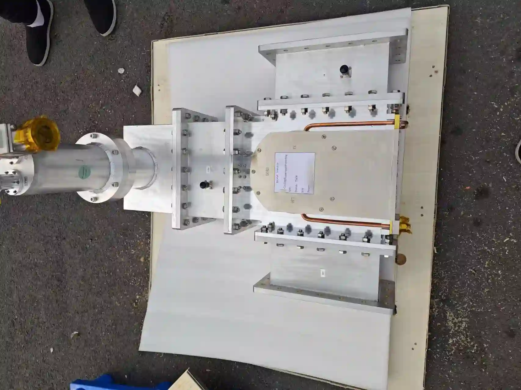
Waveguide and microwave output components on a 75 kW 915 MHz microwave generator
915 MHz RF Output & Waveguide Components
RF INTEGRATION DETAIL 75 kW High-Power System Example
BJ9
OUTPUT INTERFACE

BJ9 Is an Interface Reference — Not a Complete Compatibility Check

A matching frequency and waveguide designation are only the beginning of an integration review. Mechanical connection, flange details, microwave-head orientation, waveguide routing and the equipment-side coupling arrangement should also match the actual installation.

This becomes especially important when the generator is being integrated into an existing chamber, applicator or high-power microwave line.

01
BJ9 Reference

Used on the current published 25 kW, 75 kW and 100 kW model routes.

02
Final Flange Confirmation

Connection dimensions and mechanical details should be checked for the selected configuration.

03
Complete RF Path Review

The route from microwave head to process load should be evaluated as a complete assembly.

INTERFACE REVIEW CHECKLIST

Six Points to Confirm Before Finalizing the RF Connection

These checks are useful for both new OEM equipment and existing-source replacement projects.

01
INTERFACE

Waveguide & Flange

Confirm the waveguide reference, flange geometry, bolt pattern and mechanical connection at the microwave output.

02
ORIENTATION

Microwave-Head Direction

Check how the microwave head is positioned relative to the equipment and whether the proposed orientation matches the available installation space.

03
ROUTING

Waveguide Route

Review the distance, bends, transitions, support points and service access between the source and process equipment.

04
COUPLING

Applicator / Chamber Coupling

Confirm how microwave energy enters the chamber, applicator or load rather than treating the generator flange as the end of the RF design.

05
REFLECTION

Reflected-Power Conditions

Consider reflected microwave energy during startup, process changes and abnormal-load conditions when defining the RF protection arrangement.

06
AUXILIARIES

RF Components & Monitoring

Confirm whether isolation, water-load, tuning, monitoring or other RF components are required in the agreed project configuration.

SIMPLIFIED RF PATH

Microwave Energy Should Be Reviewed Across the Complete RF Chain

MW
Microwave Head Source output
→
ISO
Isolation As configured
→
MON
Monitoring Forward / reflected
→
WG
Waveguide Route & transitions
→
LOAD
Process Equipment Applicator / chamber

Isolation, monitoring, tuning, water-load and waveguide components are selected according to the model and project scope.

PHYSICAL INTEGRATION

Check the Microwave Head from More Than One Direction

Interface review should include the complete physical arrangement around the microwave head. Rear-side connections, cooling lines, electrical connections, mounting position and maintenance access can affect how the source fits into an existing machine.

For retrofit projects, clear photographs and drawings from several directions can significantly improve the first compatibility review.
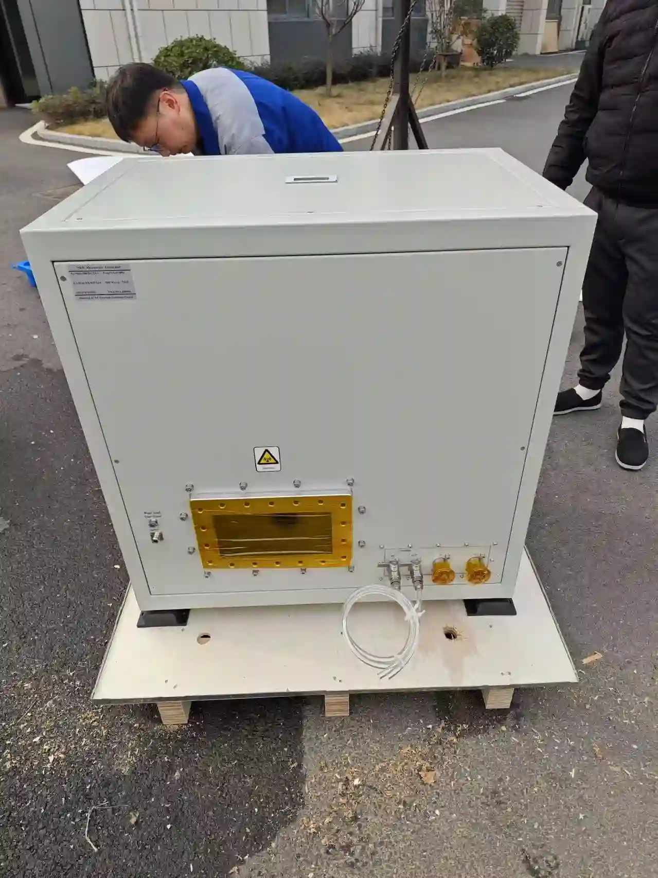
✓ Microwave output orientation
✓ Rear-side connection layout
✓ Cooling connection location
✓ Electrical / control connections
✓ Mounting and support points
✓ Service and maintenance space
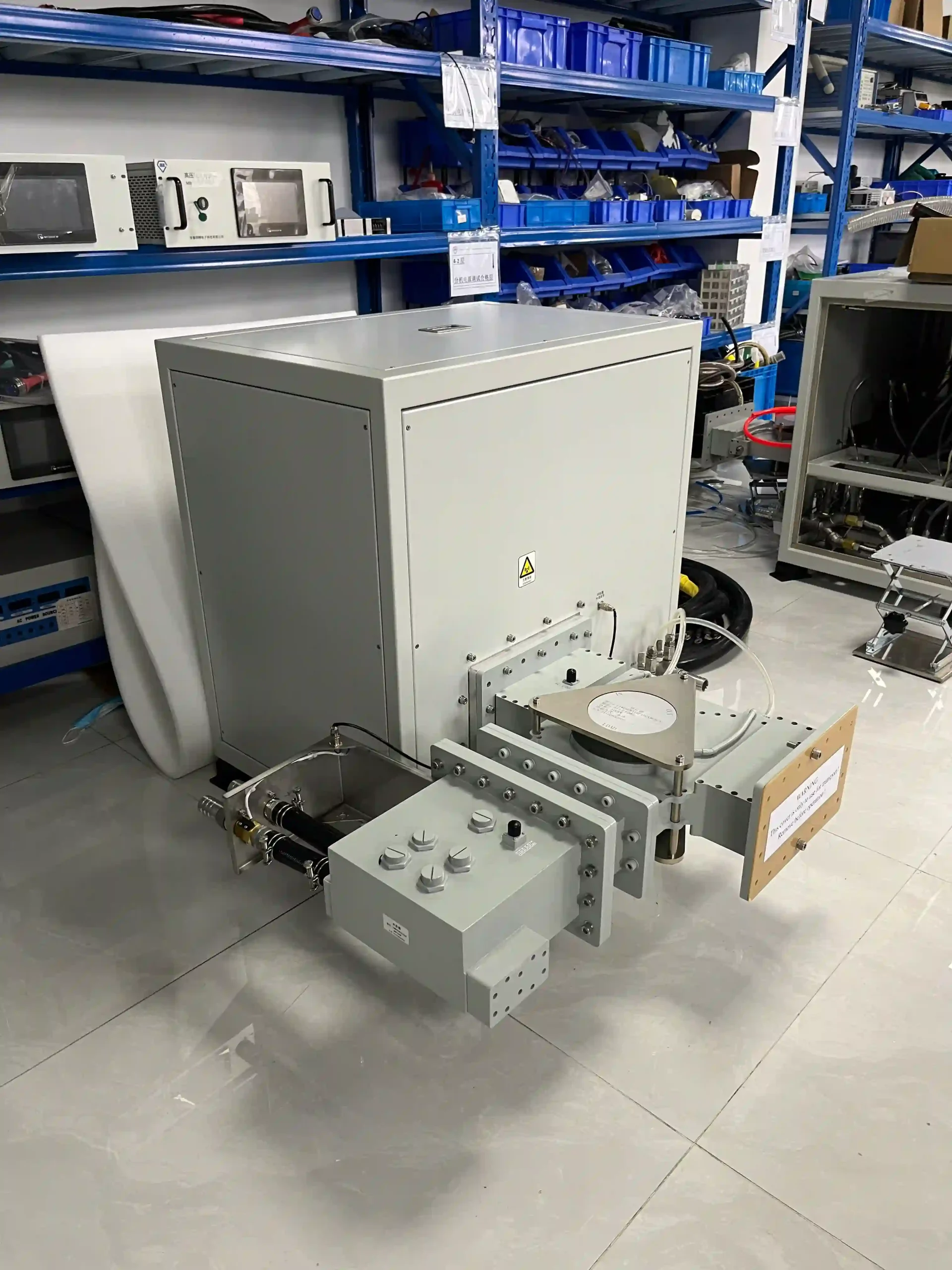
Rear interface and connection area of a 75 kW 915 MHz microwave generator head
Microwave Head Rear Interface
Physical connection detail from a 75 kW 915 MHz high-power configuration
TWO INTEGRATION ROUTES

New OEM Equipment and Existing-System Replacement Need Different Data

NEW OEM INTEGRATION

Designing the RF Path Around New Equipment

When developing new machinery, the generator and RF path can be reviewed together with the chamber, equipment layout, control architecture and available utilities.

  • Equipment layout and target source location
  • Chamber or applicator interface
  • Waveguide route and support
  • Reflected-power management
  • Cooling and electrical interfaces
  • Equipment control and safety interlocks
EXISTING-SOURCE REVIEW

Checking Compatibility Before Replacement

A replacement should not be selected from 915 MHz and rated kW alone. The existing mechanical, RF, electrical, cooling and control interfaces should be compared first.

  • Existing generator model and nameplate
  • Waveguide and flange photographs
  • Dimensions and mounting arrangement
  • Input power and cooling data
  • Control / I/O requirements
  • Current RF components and chamber connection
REQUEST AN INTERFACE REVIEW

Six Files or Data Points Make the Review Faster

You do not need a complete engineering package for the first discussion. Send whatever information is already available from the equipment.

01 Existing source nameplate
02 Waveguide / flange photos
03 Interface dimensions
04 Equipment layout drawing
05 Cooling & electrical data
06 Control / I/O requirements
Request Interface Review
NEXT: CONTROLS & PROTECTION Review HMI, communication, monitoring, interlocks and reflected-power protection.
Controls & Protection
CONTROL, MONITORING & PROTECTION

Control the Microwave Source and Coordinate the Complete Machine

High-power microwave operation depends on the generator, RF path, cooling system and customer equipment working together. Local operation, communication, status monitoring, alarms, interlocks and protective responses should therefore be reviewed as part of the complete 915 MHz system configuration.

LOCAL & COMMUNICATION CONTROL

Match the Generator Control to Your Equipment Architecture

The selected control package should define how the generator is started, stopped, adjusted and permitted to operate, as well as how status and fault information are exchanged with the customer’s equipment.

Current high-power configurations support local or communication-based operation according to model. The documented 75 kW configuration provides local HMI operation and RS485 communication.

HMI
Local Operation

Generator commands, power setting, status and fault information.

485
Communication

RS485 is documented for the current 75 kW high-power configuration.

I/O
Equipment Interlocks

Generator operation can be coordinated with agreed machine permissives.
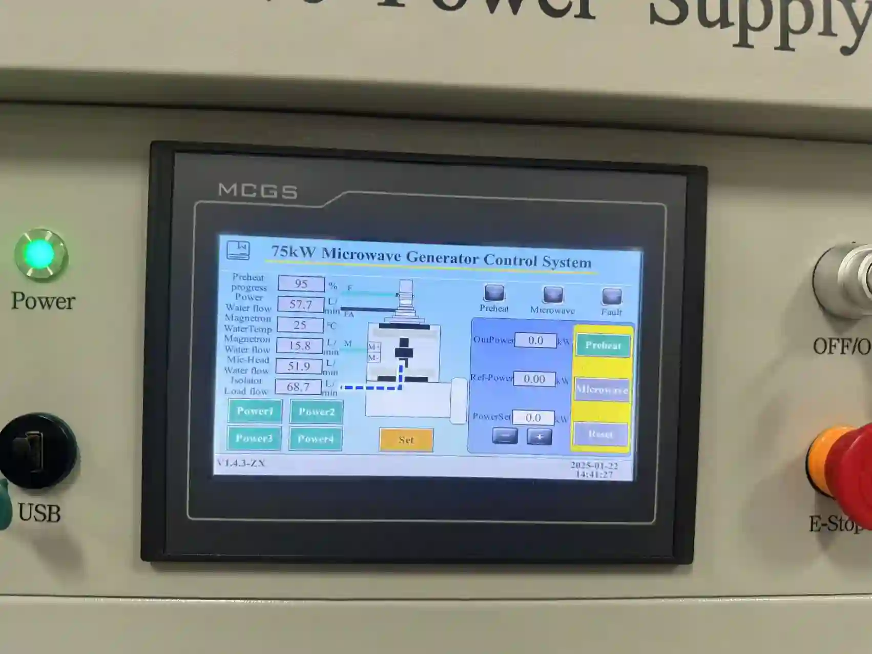
HMI control interface of a 75 kW 915 MHz high-power microwave generator
75 kW Local HMI Control Interface
75 kW CONTROL EXAMPLE Local HMI & Generator Monitoring
HMI
CONTROL & MONITORING FUNCTIONS

Define What the Generator and Customer PLC Need to Exchange

Exact displayed parameters, commands, communication details and signal lists are confirmed for the selected model and project.

HMI
LOCAL CONTROL

Start, Stop & Power Setting

Local operator controls can provide generator commands, power adjustment, operating status and fault information according to model configuration.

COM
COMMUNICATION

Customer Control Interface

Define the required communication method, commands, monitored data and controller relationship before integrating the microwave source.

ST
STATUS

Operating Status

Ready, operating, standby, alarm and fault states can be coordinated with the customer equipment according to the selected control package.

ALM
ALARMS

Alarm & Fault Information

Fault information helps operators identify electrical, thermal, cooling, RF or equipment-interlock conditions that prevent normal operation.

RF
RF MONITORING

Forward / Reflected Power

Forward and reflected microwave-power monitoring can be included where the selected RF configuration contains the required monitoring components.

INT
INTERLOCK

Equipment Permissives

Generator operation can be linked to agreed cooling, chamber, RF and equipment conditions so that the microwave source operates within the machine sequence.

TYPICAL CONTROL RELATIONSHIP

Local HMI, Generator Controller and Customer Equipment

HMI
Local Operator Commands · status · alarms
CTRL
Generator Controller Power · logic · protection
PLC
Customer Equipment Commands · permissives · I/O
INPUT CONDITIONS Cooling · Electrical · RF · Equipment Interlocks
CONTROL RESPONSE Status · Alarm · Interlock · Protective Action
PROTECTION & INTERLOCK REVIEW

Monitor the Conditions That Matter to High-Power Operation

Protection thresholds, shutdown actions and recovery logic remain specific to the selected generator configuration.

H2O
COOLING

Water-Flow Conditions

Cooling-water conditions can form part of the generator permissive and protective logic.

°C
THERMAL

Temperature Conditions

Temperature monitoring helps protect the microwave head and electrical power components.

HV
ELECTRICAL

Electrical Protection

Electrical operating conditions and faults form part of the high-power generator protection strategy.

ARC
ABNORMAL RF

Arc Conditions

Arc-related protection can be included according to the selected generator and RF configuration.

REF
REFLECTED POWER

Reflected-Power Management

Reflected microwave energy should be reviewed with the RF isolation, monitoring and equipment-load conditions.

INT
MACHINE LOGIC

Safety Interlocks

Generator operating permission should be coordinated with the agreed machine and process-equipment conditions.

REFLECTED-POWER MANAGEMENT

Reflected Power Is a System Condition — Not Only a Generator Setting

Reflected microwave energy is affected by the load, chamber or applicator, coupling conditions and RF transmission path. Monitoring and protective logic should therefore be reviewed together with the complete microwave system.

MW
Microwave Source Forward power
RF
RF Protection Path Isolation / monitoring
LOAD
Applicator / Chamber Process load
← Reflected Microwave Energy
PROTECTION RESPONSE Monitoring → Alarm / Interlock Logic → Model-Specific Protective Action
75 kW
HIGH-POWER CONTROL EXAMPLE

Documented Functions on the 75 kW Configuration

01 Local HMI

Local HMI operation is documented for the 75 kW configuration.

02 RS485

RS485 communication is documented for this high-power configuration.

03 Operating Monitoring

Generator status and fault information form part of the high-power control architecture.

04 Multiple Protection Functions

Electrical, temperature, water-flow and arc-related protections are documented.

i

Communication registers, exact protection thresholds, response times and recovery logic are confirmed for the selected generator configuration.

CONTROL DATA FOR TECHNICAL REVIEW

Tell Us How the Generator Must Communicate with Your Machine

For a new OEM system or replacement project, provide the control relationship required between the microwave source and your equipment.

01 Local HMI requirement
02 Remote start / stop
03 Required communication
04 Customer PLC / controller
05 Required monitored data
06 Alarm / fault signals
07 Equipment interlocks
08 RF monitoring requirements
Send Control & I/O Requirements
NEXT: COOLING & INSTALLATION Review cooling capacity, site power and installation requirements for high-power operation.
Cooling & Installation
COOLING, SITE POWER & INSTALLATION

Prepare the Site for a High-Power 915 MHz Microwave Generator

High-power microwave integration requires the generator, cooling system, electrical supply and installation layout to be reviewed together. Before final model selection, confirm the available cooling capacity, site electrical conditions, equipment location and service access.

WATER-COOLED HIGH-POWER CONFIGURATIONS

Confirm Cooling Capacity Before the Generator Is Finalized

Current published high-power 915 MHz configurations use water cooling. The cooling system must support the selected microwave generator under the actual operating and site conditions.

Required flow, pressure, temperature conditions and heat-rejection capacity should be confirmed for the selected model. A single cooling value should not be assumed across every 25–100 kW configuration.

01
Available Cooling Capacity

Confirm whether the project uses a dedicated chiller or an available plant cooling-water system.

02
Supply & Return Conditions

Cooling-water connections and operating conditions should match the selected generator configuration.

03
Cooling Interlock

Cooling status can form part of the generator permissive and protective control logic.
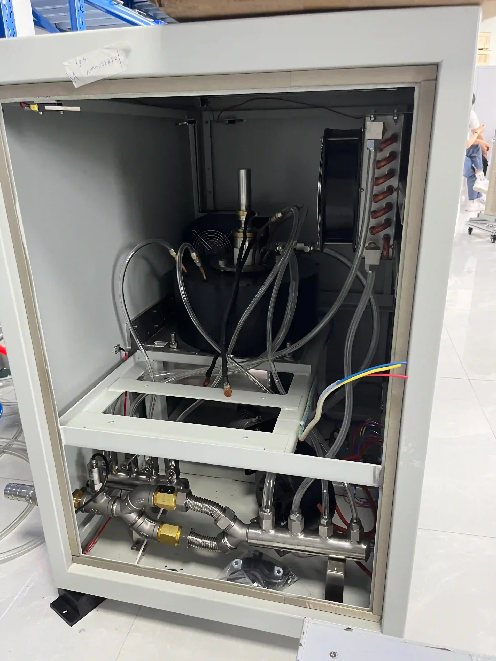
Internal cooling piping of a 75 kW 915 MHz high-power microwave generator
75 kW Internal Cooling Piping
HIGH-POWER COOLING EXAMPLE Internal Water-Cooling Arrangement
H₂O
SITE ELECTRICAL REVIEW

Confirm the Available Electrical Supply Before Quotation

Input requirements vary by generator configuration. Provide actual site data instead of assuming one universal supply voltage for the complete 915 MHz series.

V
INPUT SUPPLY

Voltage

Provide the available site input voltage so the electrical configuration can be reviewed.

Hz
GRID

Supply Frequency

Confirm the local electrical-supply frequency together with the available incoming power conditions.

kVA
CAPACITY

Available Electrical Capacity

Verify that the facility can support the complete generator and required auxiliary-system electrical demand.

CB
DISTRIBUTION

Upstream Protection

Incoming distribution and protective arrangements should be coordinated with the selected equipment.

PE
SAFETY

Grounding

Confirm suitable protective grounding as part of the site electrical and equipment installation.

AC
CONNECTION

Power Connection Route

Review incoming cable routing and connection space together with cabinet location and installation access.

EQUIPMENT LAYOUT

Plan the Cabinet, Microwave Head and RF Path as One Installation

The power cabinet, microwave head and process equipment may occupy different positions. Cable routing, cooling lines, microwave-head location, waveguide path and maintenance access should therefore be considered together.

01
CAB

Power & Control Cabinet

Position the cabinet where electrical connection and service access can be maintained.

02
CBL

Cable & Control Routing

Confirm the connection route between the cabinet, microwave head and customer equipment.

03
MW

Microwave Head

Position the microwave head according to the RF output direction and mechanical arrangement.

04
WG

Waveguide Path

Coordinate waveguide routing, RF components, supports and maintenance access.

05
LOAD

Process Equipment

Confirm the final chamber or applicator interface at the process side.

INSTALLATION REVIEW

Eight Site Conditions to Confirm Before Final Configuration

Early confirmation of installation conditions reduces interface changes later in the equipment-integration process.

01
Installation Space

Provide the available cabinet and microwave-head installation area.

02
Service Clearance

Allow access for inspection, connections and routine maintenance.

03
Waveguide Route

Confirm routing space, supports, transitions and process connection.

04
Cooling-Pipe Route

Define supply and return routing between cooling equipment and generator components.

05
Electrical Distribution

Confirm the incoming supply and connection route to the power cabinet.

06
Ambient Conditions

Provide relevant operating-environment information for the planned installation area.

07
Equipment Interlocks

Identify machine conditions that must permit or inhibit microwave operation.

08
Maintenance Access

Avoid layouts that restrict access to the cabinet, microwave head or RF components.

SYSTEM-LEVEL INSTALLATION

Utilities and RF Integration Must Be Reviewed Together

AC
Site Power Voltage · frequency · capacity
H₂O
Cooling Supply · return · capacity
MW
Microwave Generator Power cabinet + microwave head
RF
Waveguide System Interface · routing · protection
LOAD
Process Equipment Chamber / applicator
INSTALLATION ROUTE

New OEM Systems and Retrofit Projects Need Different Checks

NEW OEM SYSTEM

Design Utilities Around the Complete Microwave System

For a new machine, the generator, cooling system, electrical distribution and equipment layout can be coordinated before the final mechanical design is fixed.

  • Target power and generator route
  • Cabinet and microwave-head positions
  • Chiller or plant cooling arrangement
  • Site input power
  • Waveguide route
  • Control and interlock architecture
RETROFIT / REPLACEMENT

Compare Existing Utilities Before Selecting the Replacement

Existing electrical and cooling systems should not be assumed to suit a new microwave generator simply because nominal frequency and microwave power are similar.

  • Existing generator nameplate
  • Current input electrical data
  • Existing cooling-system information
  • Cabinet and head dimensions
  • Current cable and pipe routes
  • Existing control interfaces
SITE DATA FOR TECHNICAL REVIEW

Send Your Available Utilities and Installation Conditions

These basic site inputs help determine whether the initial generator configuration fits the electrical, cooling and mechanical conditions of the project.

01 Site input voltage
02 Supply frequency
03 Available electrical capacity
04 Cooling-system information
05 Installation-space dimensions
06 Equipment-layout drawing
07 Waveguide route / interface
08 Destination country
Send Site Conditions
NEXT: APPLICATIONS See where high-power 915 MHz microwave generators can be integrated into industrial and OEM systems.
View Applications
915 MHz MICROWAVE APPLICATIONS

Where Can a High-Power 915 MHz Microwave Generator Be Integrated?

High-power 915 MHz microwave generators can serve as the microwave source inside industrial heating, drying, plasma, advanced-material and custom OEM equipment. Generator selection should be coordinated with the load, applicator or chamber, RF path, target power, control architecture, cooling system and installation conditions.

PRIMARY APPLICATION FAMILIES

Three Main Routes for High-Power 915 MHz Integration

The microwave generator provides the source power; the complete equipment determines how that energy is delivered to the process.

HEAT
INDUSTRIAL PROCESSING

Industrial Heating & Drying

A 915 MHz microwave source can be evaluated for industrial equipment designed for microwave heating, drying, dehydration and related thermal-processing applications.

Key Integration Questions
  • What material or load receives the microwave energy?
  • Is the equipment batch, continuous or conveyor-based?
  • What microwave power is required by the process design?
  • How is the applicator or chamber connected to the RF path?
Heating Drying Thermal Process OEM Equipment
MAT
ADVANCED MATERIALS

Semiconductor & Advanced-Material OEM Systems

High-power microwave generators can be considered as microwave-source subsystems for specialized material-processing equipment where the OEM defines the chamber, process environment, RF coupling and operating sequence.

Key Integration Questions
  • What process chamber or reactor will use the source?
  • What microwave power range is required?
  • What RF interface is used at the equipment side?
  • What control and interlock signals are required?
Advanced Materials Semiconductor OEM Process Equipment Integration
PL
MICROWAVE PLASMA

High-Power Plasma & Custom OEM Equipment

915 MHz high-power microwave sources can also be evaluated for plasma-generation and custom OEM systems where the machine designer requires a high-power magnetron source integrated with a dedicated RF and process architecture.

Key Integration Questions
  • What plasma source or process chamber is being used?
  • How will reflected microwave energy be managed?
  • What waveguide and coupling arrangement is required?
  • How will the source interface with the equipment controller?
Plasma High Power RF Integration Custom OEM
APPLICATION ROUTES

Common Ways the Microwave Source Enters an Industrial System

The chamber, applicator and process equipment are selected or engineered around the application.

01
DRY
THERMAL PROCESS

Drying & Moisture Removal

Microwave sources can be integrated into equipment designed for drying or moisture-removal processes where the applicator and material-handling system are engineered for the target load.

02
HT
PROCESS HEATING

Industrial Microwave Heating

High-power generator configurations can be evaluated for industrial microwave-heating equipment according to the process load, chamber and required power route.

03
MAT
MATERIAL PROCESSING

Advanced-Material Equipment

Specialized materials equipment may use the generator as an RF power subsystem while the OEM defines the process chamber and microwave-coupling architecture.

04
SEMI
OEM PROCESS EQUIPMENT

Semiconductor-Related Systems

For semiconductor-related process equipment, generator selection should be based on the actual chamber, RF architecture, controls and operating conditions.

05
PL
PLASMA

Microwave Plasma Systems

Plasma equipment can require a dedicated RF path, reflected-power strategy and equipment-level control sequence around the selected microwave source.

06
OEM
CUSTOM MACHINE

OEM Microwave Platforms

Equipment manufacturers can integrate the generator into custom microwave platforms when electrical, RF, cooling, mechanical and control interfaces are defined during system design.

APPLICATION SYSTEM ARCHITECTURE

From Microwave Source to Process Load

Application performance is created by the complete microwave system. The generator supplies microwave power, while the RF path, applicator or chamber and process load determine how that power is coupled into the equipment.

AC
Site Utilities Power + cooling
MW
915 MHz Generator Microwave source
RF
RF Delivery Protection + waveguide
APP
Applicator / Chamber Energy coupling
LOAD
Process Load Material / plasma / product
APPLICATION FIT

Seven Questions Help Define the Right Generator Route

These inputs help move the discussion from a general application name to an actual equipment configuration.

01
What Is the Process?

Describe whether the system is for heating, drying, plasma, material processing or another microwave-based operation.

02
What Is the Load?

Provide the material, process medium or chamber condition that receives microwave energy.

03
What Power Is Required?

State the target microwave power or the existing source rating for replacement projects.

04
What Is the Applicator?

Describe the chamber, reactor, applicator or equipment-side microwave interface.

05
What RF Interface Is Used?

Provide the existing or proposed waveguide, flange and coupling arrangement.

06
How Will the Machine Be Controlled?

Define local operation, PLC communication, permissives and required equipment interlocks.

07
Where Will the System Operate?

Provide the destination country together with available site power and cooling conditions.

POWER ROUTE

Match Power to the Equipment — Not Just the Application Category

Power selection depends on the process design, load, applicator or chamber, operating mode, RF conditions and available utilities. The same application category can use different generator power levels in different machines.

25 kW Published Model

Evaluate against the actual process power and interface requirements.

30 kW Project Configuration

Discuss the intended equipment and technical requirements before selection.

75 kW Published High-Power Model

A higher-power route for systems whose equipment design requires this power class.

100 kW Published Model

Final configuration depends on the complete application and installation requirements.

ENGINEERING CONSIDERATIONS

Two System-Level Factors to Review Before Final Selection

Frequency selection and process performance both extend beyond the microwave generator itself.

915
FREQUENCY SELECTION

Evaluate 915 MHz as Part of the Complete RF System

Frequency affects the microwave source, RF components, waveguide system, applicator or chamber design and destination-country requirements. When an existing process uses another microwave frequency, the source and RF path should be reviewed together before selecting a 915 MHz configuration.

Source Waveguide Applicator RF Components
PROC
PROCESS PERFORMANCE

Process Performance Depends on the Complete Microwave System

Heating rate, drying performance, temperature uniformity, plasma behavior, throughput and material response depend on the generator, applicator or chamber, RF coupling, load characteristics and process conditions. Generator selection should therefore be evaluated together with the complete process equipment.

Generator RF Coupling Load Process Conditions
APPLICATION REVIEW

Send the Process and Equipment Information You Already Have

A short application description, equipment drawing or existing-source photograph can provide enough information to begin the first generator-selection discussion.

01 Application / process
02 Target microwave power
03 Chamber / applicator
04 Material or process load
05 Waveguide / RF interface
06 Control requirements
07 Cooling / site power
08 Destination country
Discuss Your Application
NEXT: OEM & RETROFIT Review new-equipment integration and existing microwave-source replacement requirements.
OEM & Retrofit
OEM INTEGRATION, RETROFIT & PROJECT SELECTION

Integrate a New 915 MHz Source or Review an Existing System for Replacement

High-power 915 MHz microwave projects generally follow one of two routes: integration into new OEM equipment or replacement of an existing microwave source. In both cases, generator selection should consider the electrical, RF, mechanical, control and cooling interfaces of the complete machine.

OEM
NEW EQUIPMENT

New OEM Microwave Generator Integration

For new equipment, the microwave source can be reviewed together with the process chamber or applicator, RF path, machine controls, cooling arrangement and available installation space.

01
Application & Process Load

Describe the material, plasma, chamber or applicator using microwave energy.

02
Target Microwave Power

Define the required power class or initial engineering target.

03
RF Interface

Review waveguide, flange, coupling, RF components and routing.

04
Machine Control

Define local operation, communication, permissives and interlocks.

05
Site Utilities

Confirm electrical supply, cooling capacity and installation conditions.

06
Supply Scope

Clarify which generator and RF components are required within the quoted system.

Discuss OEM Integration
RET
EXISTING EQUIPMENT

Existing Generator Replacement & Retrofit

For an existing microwave system, begin with the installed generator and interface data. This helps identify which parts of the current machine may remain compatible and which interfaces may require modification.

01
Existing Generator Data

Send the current model, nameplate and available technical information.

02
Frequency & Power

Confirm operating frequency, rated microwave power and input supply.

03
Mechanical Arrangement

Provide cabinet dimensions, microwave-head dimensions and mounting information.

04
Waveguide Interface

Send flange photographs, dimensions, orientation and existing RF-path information.

05
Controls & I/O

Identify remote commands, communication, status signals and machine interlocks.

06
Cooling & Upgrade Objective

Provide cooling information and explain the reason for replacement or upgrade.

Send Existing Generator Data
RETROFIT COMPATIBILITY

Compare the Complete Interface — Not Frequency and kW Alone

Six interface groups help determine how much adaptation may be required when replacing an existing microwave source.

AC
01

Electrical

Input voltage, frequency, available capacity, grounding, protection and connection method.

RF
02

RF Interface

Waveguide, flange geometry, output direction, RF components and reflected-power handling.

MEC
03

Mechanical

Cabinet size, microwave-head dimensions, mounting, orientation and service space.

I/O
04

Control

Local control, remote commands, communication, alarms and machine interlocks.

H₂O
05

Cooling

Cooling source, capacity, connections, pipe routing and operating conditions.

SYS
06

System Scope

Existing RF components, required adapters, customer-supplied equipment and project scope.

EXISTING-SOURCE REVIEW

Photographs Can Start the First Retrofit Discussion

Complete engineering drawings are useful, but they are not necessary for the first review. Clear photographs of the current generator, nameplate, waveguide connection and installation arrangement can help identify the main interface questions.

01 Generator nameplate
02 Full equipment view
03 Waveguide / flange
04 Cabinet dimensions
05 Microwave-head dimensions
06 Electrical data
07 Cooling connections
08 Control / I/O details
FIRST REVIEW PACKAGE Existing Microwave Source
NAMEPLATE DATA
Frequency
Existing value
Rated Power
Existing value
Input Supply
Site data
Model
Current source
IMG Equipment Photos
RF Flange Details
DWG Dimensions
I/O Control Data
PROJECT SELECTION PROCESS

From Requirement Review to Final Project Configuration

A structured review helps clarify the power route, interfaces and system scope before final equipment selection.

01
RFQ
STEP 01

Requirement Intake

Application, country, power and project objective.

02
kW
STEP 02

Power Route

Review the appropriate 915 MHz power configuration.

03
INT
STEP 03

Interface Review

Electrical, RF, mechanical, controls and cooling.

04
BOM
STEP 04

Define Scope

Generator, project RF components and customer interfaces.

05
CFG
STEP 05

Configuration

Confirm the proposed technical and commercial configuration.

06
DOC
STEP 06

Order Confirmation

Confirm agreed interfaces, testing and documentation.
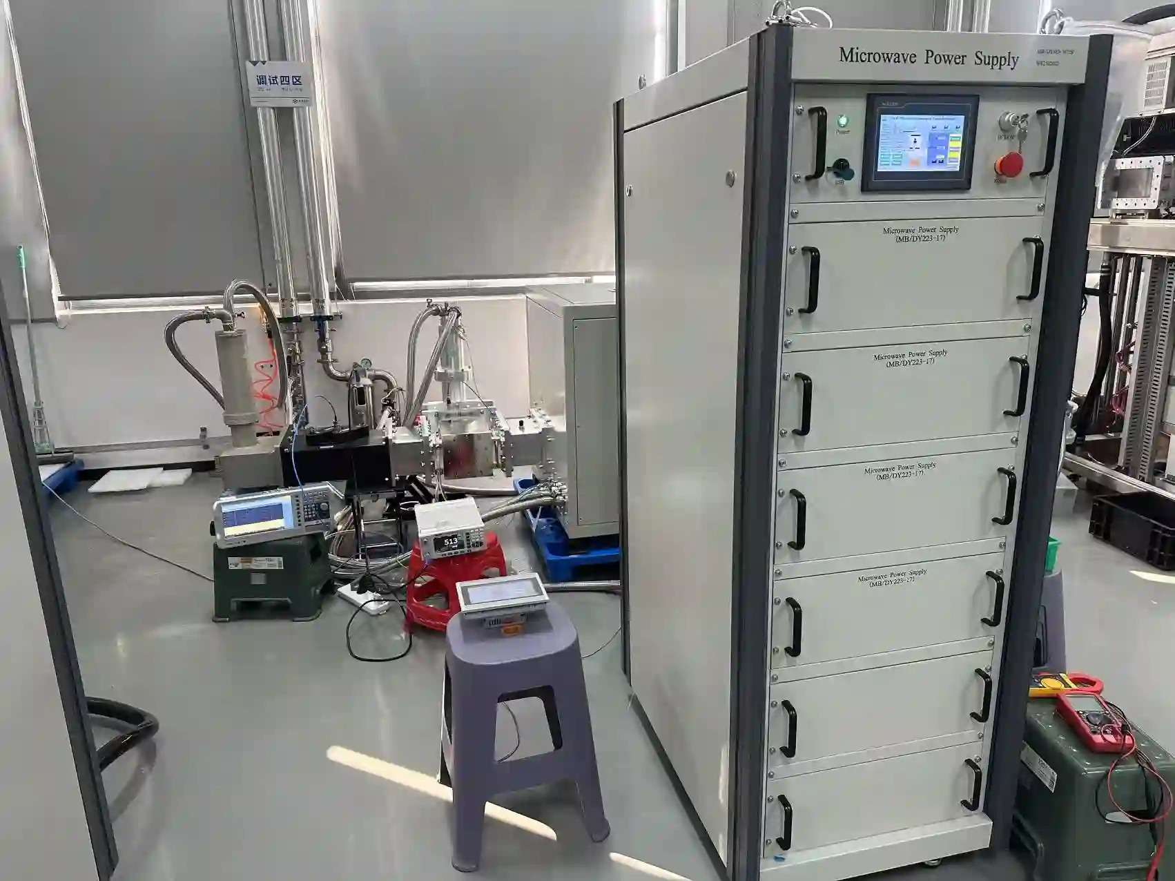
Testing scene for a 75 kW 915 MHz high-power microwave generator system
75 kW Microwave Generator Testing Scene
PROJECT TESTING EXAMPLE 75 kW High-Power Generator Configuration
TEST
TESTING & TECHNICAL CONFIRMATION

Define the Required Test Scope Before Delivery

Testing requirements should be coordinated with the selected generator configuration and project scope. This may include functional checks, operating-status verification and agreed interface or acceptance items.

For OEM projects, discussing the acceptance requirements before the final configuration is confirmed helps align the generator, controls, RF interfaces and project documentation.

01
Functional Operation

Confirm agreed generator operating and control functions.

02
Interface Checks

Review relevant RF, electrical, cooling and control interfaces.

03
Acceptance Scope

Define required project-specific verification before delivery.

PROJECT DOCUMENTATION

Confirm Technical Documents with the Selected Configuration

The required technical-document package depends on the selected model, project interfaces and agreed delivery scope. Confirm documentation requirements during the technical review.

DWG Interface Information

Mechanical, electrical and RF information required for integration.

CTRL Control Information

Required control and communication information according to configuration.

TEST Agreed Testing

Testing and acceptance items defined by the confirmed project scope.

DOC Technical Documents

Documentation supplied according to the agreed equipment configuration.

DELIVERY PREPARATION

Prepare the Microwave Head and System Components for Delivery

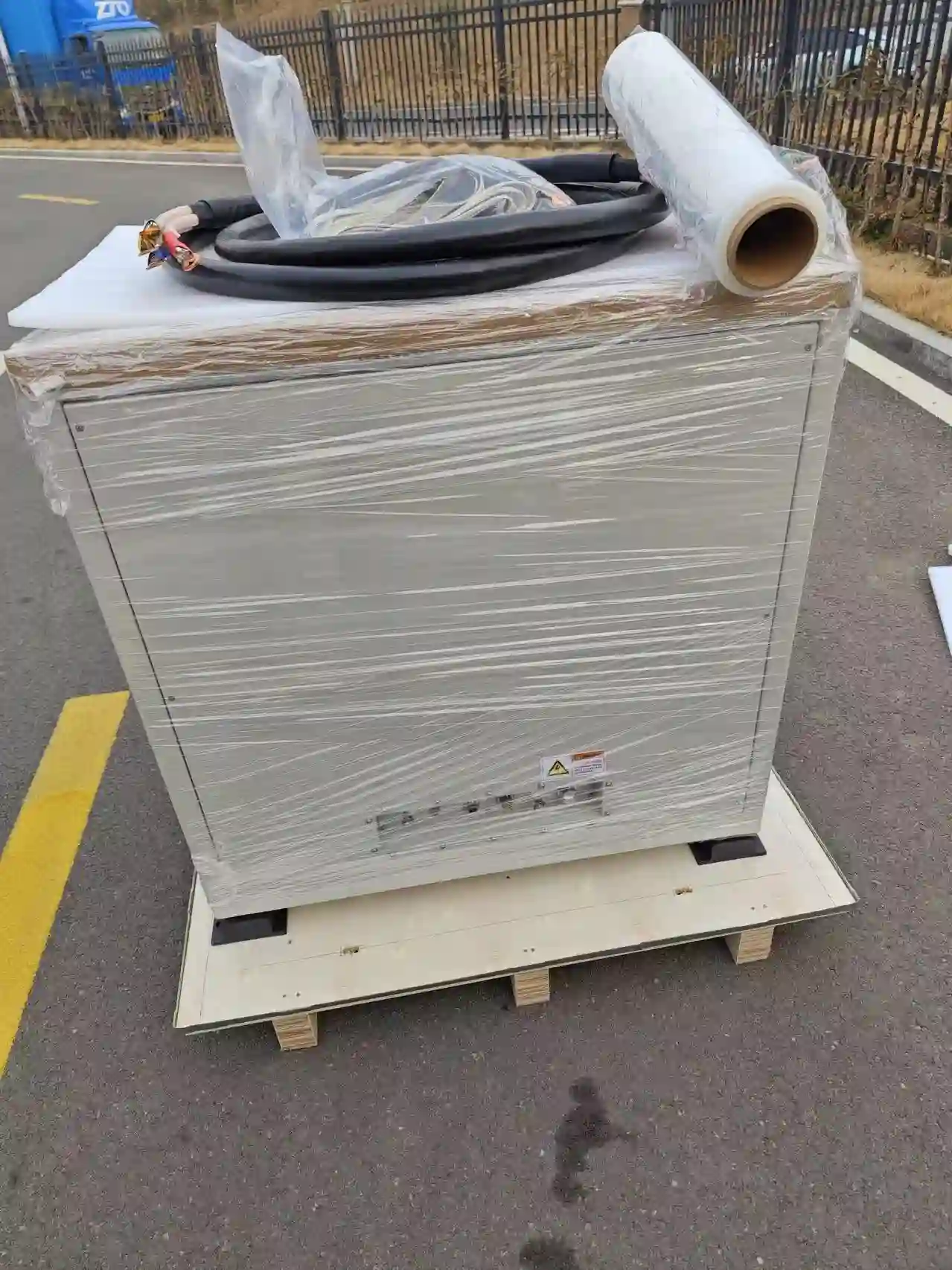
High-power microwave projects can include separate cabinets, microwave heads, cables and RF components. Packaging and delivery preparation should follow the actual equipment configuration and agreed supply scope.

Before shipment, confirm the equipment list, interface documentation and installation information required by the receiving engineering team.
01 Equipment List
02 Interface Documents
03 Installation Data
04 Delivery Scope
Packaging of a 75 kW 915 MHz high-power microwave generator head for delivery
75 kW Microwave Head Packaging
DELIVERY PREPARATION EXAMPLE High-Power Microwave Head Packaging
PKG
START THE TECHNICAL REVIEW

Send the Information Available for Your Project

You do not need to identify the exact generator model before contacting us. Start with your application requirements or the existing microwave-source information.

01 New OEM or retrofit
02 Application / process
03 Target / existing power
04 Existing generator data
05 Waveguide / flange
06 Site power & cooling
07 Control / I/O requirements
08 Drawings / photographs
Start Technical Review
NEXT: TECHNICAL FAQ Get direct answers about 915 MHz selection, power levels, interfaces, cooling and retrofit projects.
View Technical FAQ
915 MHz MICROWAVE GENERATOR FAQ

Technical Questions About 915 MHz High-Power Microwave Generators

Direct answers to common questions about power selection, BJ9 waveguide interfaces, cooling, controls, OEM integration and replacement of existing 915 MHz microwave sources.

FREQUENCY 915 MHz

High-power microwave source platform for industrial and OEM integration.

POWER ROUTES 25 / 30 / 75 / 100 kW

Published models plus a project-configured 30 kW route.

TECHNOLOGY Magnetron-Based

Current high-power generator configurations use magnetron sources.

PROJECT TYPE OEM / Retrofit

New-machine integration and existing-source review.

01

What is a 915 MHz microwave generator?

A 915 MHz microwave generator is the microwave-power source used inside industrial or OEM equipment. A typical source package combines the power and control cabinet, microwave head, magnetron, controls and required connections.

The complete project may also include selected RF components such as waveguide, isolation, monitoring or other integration hardware according to the agreed system scope.

02

What 915 MHz microwave-generator power levels are available?

Current high-power selection routes include published 25 kW, 75 kW and 100 kW models, together with a project-configured 30 kW route.

The appropriate power level should be selected from the actual process, chamber or applicator, RF conditions, control requirements, cooling capacity and site utilities.

03

Is the 30 kW version a standard published model?

The 30 kW route is treated as a project-configured option rather than an independent published model on this page. Its interfaces and technical configuration should therefore be reviewed against the specific project requirements.

04

Do 915 MHz microwave generators use BJ9 waveguide?

BJ9 is used as the microwave-output interface reference on the current published 25 kW, 75 kW and 100 kW model routes.

BJ9 alone does not confirm full compatibility. Final flange geometry, orientation, waveguide route, RF components and equipment-side coupling should still be checked for the selected model and installation.

05

Can a 915 MHz generator replace my existing microwave source?

It can be evaluated for replacement, but compatibility should be checked across the electrical, RF, mechanical, control and cooling interfaces of the existing machine.

For the first review, send the existing generator nameplate, equipment photographs, waveguide and flange details, dimensions, site electrical data, cooling information and control requirements.

06

Are 915 MHz and 2450 MHz microwave generators interchangeable?

Frequency selection affects the microwave source, waveguide system, RF components, applicator or chamber and the overall equipment design.

Equipment designed around another microwave frequency should therefore be reviewed as a complete RF system before changing to a 915 MHz source.

07

What control options are available for a 915 MHz generator?

High-power configurations can support local operation and communication-based integration according to the selected model and project.

The documented 75 kW configuration includes local HMI operation and RS485 communication. Exact communication data, commands, signals and interlocks are confirmed for the ordered configuration.

08

Are high-power 915 MHz microwave generators water-cooled?

Current published high-power configurations use water cooling. Cooling capacity, supply and return conditions, connection arrangement and related operating requirements should be confirmed for the selected generator.

A single water-flow, pressure or inlet-temperature value should not be applied to the complete 25–100 kW range.

09

Does the microwave generator include the process chamber or applicator?

The microwave generator is primarily the microwave-source subsystem. The customer or equipment OEM generally provides the process chamber, applicator or complete process machine unless these items are specifically included in the quoted scope.

Project-specific RF components and integration hardware can be discussed separately when defining the complete supply boundary.

10

What information is needed to select a 915 MHz microwave generator?

Start with the application, destination country, target or existing microwave power, chamber or load, waveguide and flange information, reflected-power conditions, site electrical supply, cooling capacity and required control interface.

For retrofit projects, photographs, dimensions and the existing generator nameplate are especially useful.

11

Can a 915 MHz microwave generator be used in any country?

Microwave-frequency and industrial RF requirements can vary by country or region. The destination country should therefore be provided during project selection so the intended frequency and installation can be reviewed against the applicable local requirements.

NEED A PROJECT-SPECIFIC ANSWER?

Send Your Application or Existing Generator Information

For a new OEM system, describe the process, target power, chamber and site conditions. For replacement projects, send the existing nameplate, equipment photographs and interface information.

NEXT: REQUEST A QUOTE Send your application, power requirement and interface data for generator selection.
Request a Quote
ENGINEERING RFQ

Request a 915 MHz Microwave Generator Configuration

Tell us what the microwave source needs to connect to. For a new OEM system, provide your application and equipment requirements. For a retrofit project, send the existing generator and interface information so the replacement route can be reviewed.

OEM
NEW EQUIPMENT

New OEM Integration

Start with the process, target microwave power, chamber or applicator, RF interface, controls and available site utilities.

RET
EXISTING EQUIPMENT

Retrofit / Replacement

Send the existing generator nameplate, equipment photographs, flange or waveguide details, controls, cooling and electrical information.

SEL
MODEL SELECTION

Not Sure Which Power Level?

You do not need to choose 25, 30, 75 or 100 kW before contacting us. Provide the project conditions and start with a technical review.

INFORMATION FOR GENERATOR SELECTION

What Should You Include in the RFQ?

Send what you already know. Missing items can be discussed during the technical review.

01
Application

Heating, drying, plasma, advanced materials, OEM equipment or another microwave process.

02
Destination Country

Required for frequency and installation-condition review.

03
Target / Existing Power

Required microwave power or current generator rating.

04
Frequency

Confirm whether the project is already designed around 915 MHz or another frequency.

05
Quantity

Number of microwave generator systems required for the project.

06
Chamber / Process Load

Describe the applicator, reactor, chamber, material or process equipment.

07
Waveguide / Flange

Provide the proposed or existing RF interface and available drawings or photographs.

08
Reflected-Power Conditions

Share available information about the RF load, isolation or reflected-power requirements.

09
Site Electrical Supply

Voltage, frequency and available electrical capacity at the installation site.

10
Cooling

Available chiller or plant cooling system and known cooling-site conditions.

11
Controls & Communication

Local HMI, customer PLC, remote control, communication and interlock requirements.

12
Project Scope

Generator only or additional RF components, interface support, testing and documentation.

USEFUL FILES FOR TECHNICAL REVIEW

Have Existing Equipment? These Files Can Accelerate the Review

IMG
Equipment Photos

Overall generator, cabinet, microwave head and installation views.

TAG
Nameplate

Model, power, frequency and existing equipment identification.

RF
Waveguide Interface

Flange close-ups, dimensions, orientation and RF-path information.

DWG
Layout / Drawings

Available installation, interface or equipment drawings.

I/O
Control Information

PLC, communication, commands, signals and interlocks.

UTIL
Site Utilities

Electrical supply, cooling system and installation conditions.

WHAT HAPPENS NEXT?

A Practical Engineering Review Before Final Configuration

01 Application Review

Understand the process, equipment and project objective.

02 Power Selection

Screen the appropriate 915 MHz generator route.

03 Interface Review

Check RF, electrical, mechanical, controls and cooling.

04 Define Scope

Clarify generator, RF components and customer interfaces.

05 Technical Proposal

Confirm the proposed project configuration.

915 MHz HIGH-POWER MICROWAVE GENERATORS

Ready to Review Your Project?

Send your application requirements or existing generator information. We can start from the data you already have and review the appropriate 915 MHz generator route.