
Shore Power Engineering Guide
Modbus RTU and Communication Interfaces for Shore Power
A protocol name alone does not define a usable shore power interface. Physical communication, register meaning, data quality, control authority, fault behavior and FAT verification must all be defined together.
Direct answer: specifying “Modbus RTU required” is only the starting point. A working interface must also define the physical connection, device roles, communication settings, register and data model, scaling, polling behavior, write permissions, command feedback and the response to communication loss.
Two devices can both support Modbus and still fail to exchange useful information. They can also communicate successfully while interpreting the same data differently.
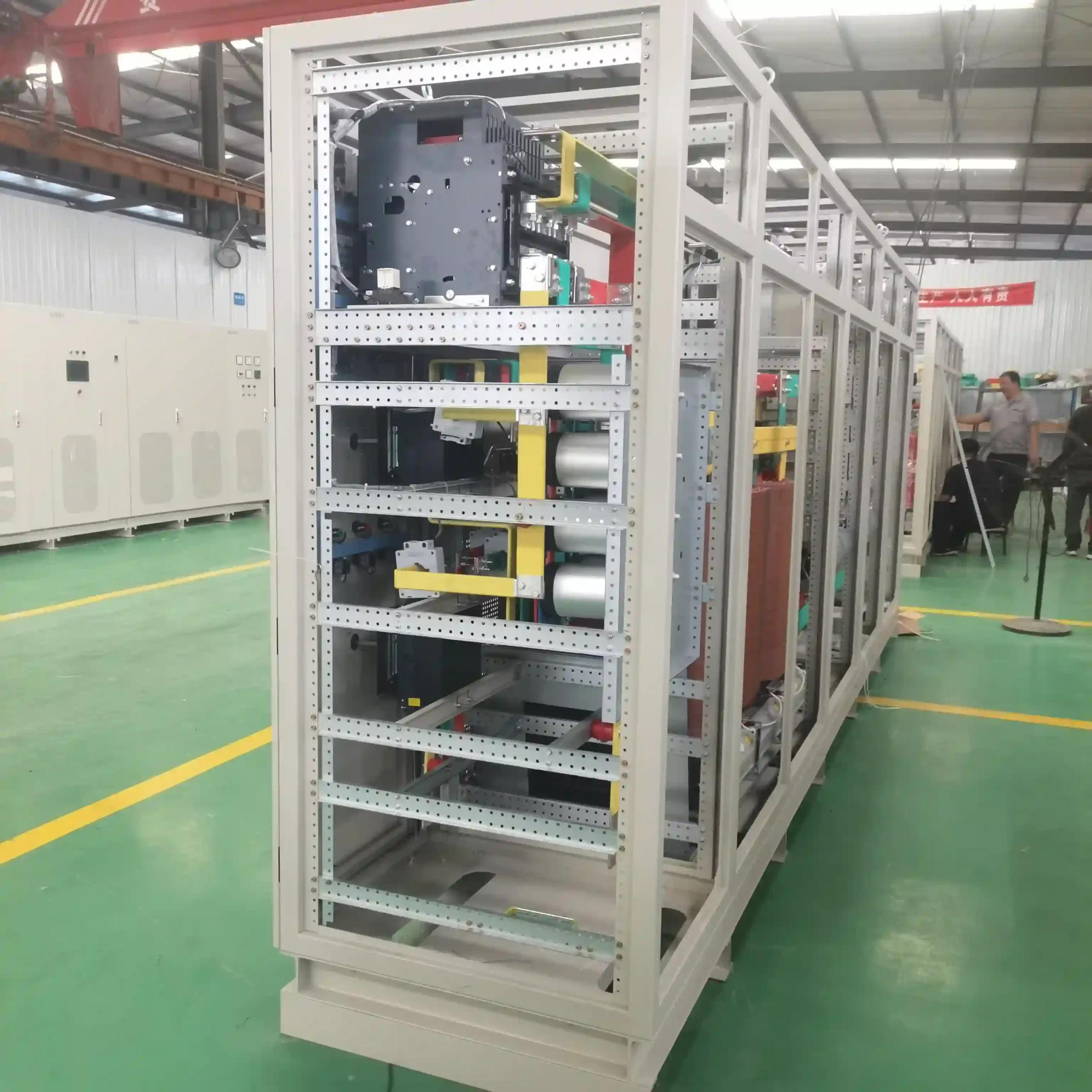
Start With the Communication Boundary
Before selecting a protocol or preparing a register map, define which systems actually need to exchange information.
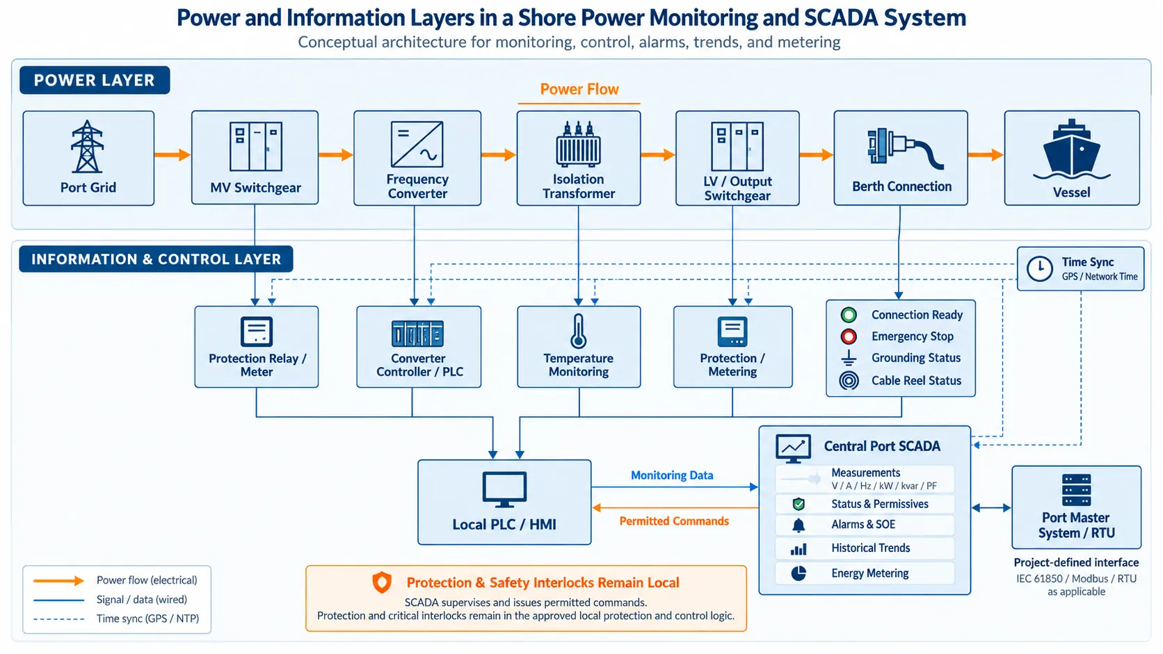
A shore power frequency converter may exchange operating data with the package PLC. Protection relays and energy meters may provide measurements and status. The PLC may pass selected information to the port SCADA system. Berth connection equipment, HVAC controllers and cable-management equipment can introduce additional interfaces.
These devices do not automatically belong on the same network simply because they support a common protocol. The communication architecture should reflect the required data flow, availability, maintenance boundary, control authority and owner integration requirements.
For the equipment layers behind these signals, see our shore power system architecture and components page.
Understand the Device-to-SCADA Data Path
A useful way to define the interface is to follow the data from its source to the operator.
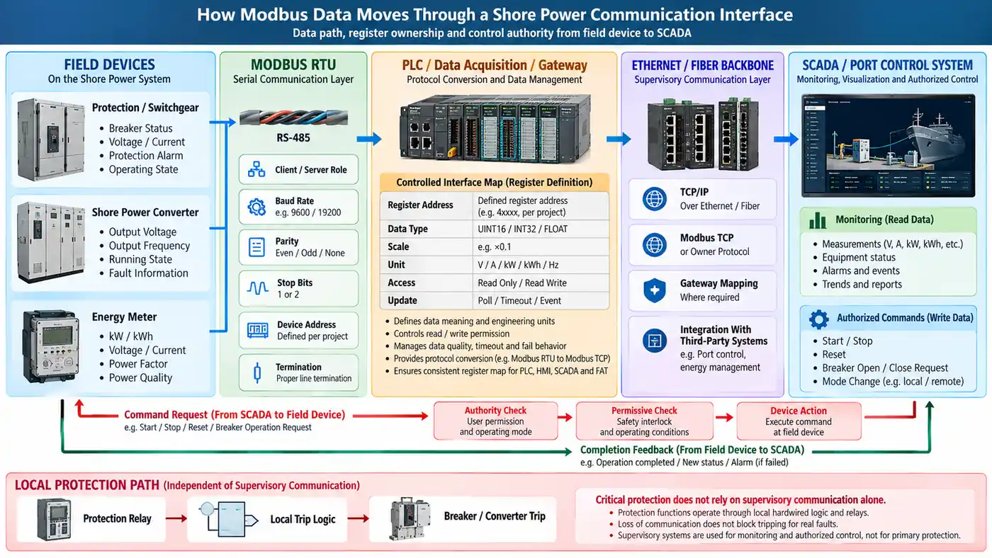
A field device may provide measurements or status through Modbus RTU. A PLC, data-acquisition unit or gateway may collect those values. The supervisory layer may then use Ethernet or fiber to carry selected information to an HMI, SCADA system or port control platform.
The reverse path needs the same discipline. A command entered at SCADA does not move directly from a screen to a breaker simply because communication exists. The request may pass through a PLC or gateway, be checked against the permitted control mode and local interlocks, and then require device feedback before the operation is considered complete.
In one shore power project completed with project partners, the monitoring architecture used a distributed structure with fiber Ethernet between field systems and the monitoring center. The project also included measurement, operating status, remote control and third-party system integration.
Define the Modbus RTU Serial Layer
Modbus RTU is commonly implemented over an RS-485 serial interface. The protocol name still does not define the complete physical and serial implementation.
The interface schedule should state whether the segment uses a two-wire or four-wire arrangement, the cable and shielding requirements, grounding and isolation method, termination arrangement and the planned route.
It should also define:
- Device communication roles
- Baud rate
- Data bits, parity and stop bits
- Device addresses
- Connector or terminal assignments
- Topology and planned segment arrangement
These are not administrative details. Incorrect termination, duplicated addresses or inconsistent serial settings can prevent communication even when every individual device is healthy.
Final cable length, topology and device count should be checked against the actual transceivers, cable characteristics, baud rate and equipment requirements rather than copied from a generic project template.
Build a Controlled Register Map
The register map is one of the most important interface documents in a Modbus-based shore power system.
For every exchanged item, define what the value means and how it is represented. The controlled schedule should identify the source device, address, applicable function, read or write permission, data type, scaling, engineering unit and the expected interpretation at the receiving system.
Modbus coils and discrete inputs are single-bit data objects, while input and holding registers are 16-bit words. That does not mean every engineering value naturally fits into one register.
A voltage may be transmitted as an integer with a scaling factor. An energy total may require multiple registers. A device may expose a signed integer or floating-point value using more than one 16-bit register.
If those conventions are not defined, a message can be received without communication errors while the displayed engineering value is still wrong.
The register schedule should therefore be a controlled engineering document shared by the PLC, HMI, SCADA and FAT teams. Firmware updates or device replacement should trigger review where the interface may change.
For the definition and ownership of measurements, states, alarms and commands, see our shore power telemetry and remote control points guide.
Define Multi-Register Data Clearly
Modbus defines how protocol data are transported, but project-specific equipment often uses two or more 16-bit registers to represent larger engineering values.
If a 32-bit integer, accumulated value or floating-point value spans multiple registers, the interface schedule should state its data type, scaling and register order explicitly. The sender and receiver must interpret the same registers in the same way.
The correct verification question is whether the receiving system displays the expected value throughout the required operating range.
Set Polling, Timeout and Data-Quality Behavior
Serial bandwidth is finite. Polling every value from every connected device at the same high rate can increase traffic and create slow responses or nuisance communication timeouts.
Different points also have different operational value. A rapidly changing operating measurement may justify a shorter update interval than a maintenance counter or accumulated energy total. Critical event handling may be performed locally rather than relying on a slow supervisory polling cycle.
The interface specification should define retry behavior, timeout criteria and when a device is declared offline.
Most importantly, loss of communication must not turn the last valid value into apparently live information. If current data can no longer be obtained, the supervisory system should distinguish invalid or stale data from a legitimate zero or unchanged value.
After communication recovers, the project should also define whether values return automatically, require validation or create a communication-restored event.
Separate Read Access From Control Authority
Read access and control authority are not the same thing.
A supervisory system may need to read voltage, current, frequency, energy, breaker status, converter state and alarms without being permitted to modify device settings.
Where write functions are required, expose only the commands or parameters that the receiving system is authorized to change. Remote converter start, reset, mode selection or breaker operation should remain subject to the approved operating mode, local permissives and completion feedback.
Our shore power PLC and HMI control guide explains the wider relationship between control modes, permissives and operating sequences.
Keep Critical Protection Independent of Supervisory Communication
Modbus can transport protection measurements, device status and trip indications to a monitoring system. That does not mean the supervisory communication link should become the only path on which critical electrical protection depends.
Overcurrent, overtemperature, emergency shutdown and other project-defined protective functions should operate through the approved local protection and trip architecture for the equipment.
The monitoring system can display the operation, record the event and support diagnosis. This separation prevents a damaged communication cable, failed gateway or unavailable supervisory controller from automatically becoming a failure of the underlying protection function.
Communication-loss behavior should instead be defined in the project cause-and-effect philosophy. Depending on which information or function is lost, the approved response may allow existing operation to continue, inhibit a new start or initiate a controlled stop.
There is no universal response for every communication fault.
Coordinate Modbus RTU With Ethernet and Other Protocols
A shore power system does not have to use one protocol from every field device to the port control room.
A practical architecture may use Modbus RTU at the device level and Ethernet-based communication at the supervisory level. A PLC, data-acquisition controller or gateway can form the handoff between those layers.
In one project completed with project partners, the shore power monitoring system used fiber Ethernet and TCP/IP between site equipment and the monitoring center. The same solution also provided interfaces for several equipment communication protocols and third-party systems.
Another project configuration required integration with a port control platform through IEC 61850, with data-acquisition equipment and fiber switches providing the interface to the wider substation system.
These examples are not a universal protocol architecture. Their engineering value is that they show why every gateway creates another interface boundary.
Mapping, data ownership, timeout behavior, command paths and feedback must remain clear through that boundary. A statement such as “open protocol” does not automatically mean two systems exchange the correct operational information.
Protocol Compatibility Does Not Define Cybersecurity
Successful Modbus communication does not by itself define the cybersecurity architecture.
Operational networks, engineering access, remote access, write permissions and connections to office or public networks should follow the owner's cybersecurity requirements.
Physical access matters as well. A serial interface, gateway or local engineering port can provide access to device configuration even when it is not connected directly to a general Ethernet network.
PLC, gateway and HMI configurations should be controlled, and firmware or device replacement should trigger an interface review where the communication map could change.
A replacement device that is electrically compatible but exposes a different register map is not automatically a drop-in replacement from the automation system's point of view.
Verify the Interface During FAT
A communication interface should be tested as an engineering function, not merely checked for an online indication.
Where practical, use the actual receiving system or a documented simulator. Verify representative analog values across the expected range. Check signed values where applicable, scaling, units, register interpretation and state text.
Then test commands. Confirm that permitted commands are accepted only when the required authority and permissives are present, and that the expected device feedback reaches the supervisory system.
Communication-loss testing is equally important. Disconnect or disable the interface in a controlled FAT condition and verify offline indication, stale-data handling, alarms, timeout behavior and recovery.
Finally, record the approved register-map revision and relevant software or configuration versions in the FAT documentation.
Our shore power manufacturing and FAT guide explains how communication verification fits into the wider factory acceptance process.
What Real Project Interfaces Show
Real shore power projects can combine several communication layers.
In one project configuration completed with project partners, high-voltage switchgear provided electrical measurements and supported Modbus RTU or another open-bus protocol. The wider monitoring architecture included remote operating data, equipment status, alarms, control functions and system integration over the communication network.
The engineering lesson is not that every new project should copy those protocols or that architecture.
Equipment selection, point definition, protocol selection, network architecture and control authority have to be reviewed together. Changing the owner SCADA platform, protection relay, meter, converter controller or gateway can change the communication interface even when the shore power rating remains exactly the same.
Common Shore Power Communication-Interface Errors
- Writing only “Modbus RTU” while leaving the physical layer, serial settings and data model undefined.
- Assuming that two devices supporting the same protocol automatically use compatible address, register, scaling and data-type conventions.
- Treating a successful protocol response as proof that the displayed engineering value is correct.
- Polling every point at the same rate and creating unnecessary serial-bus traffic.
- Leaving unnecessary registers writable and extending control authority beyond what the supervisory system requires.
- Displaying the last successful value as live data after communication has been lost.
- Making critical protection dependent on the continued availability of a supervisory communication link.
- Testing only healthy communication and leaving offline, timeout and recovery behavior unverified.
Information Needed for a Shore Power Communication Interface
Before finalizing the interface, prepare one controlled schedule covering the information that actually determines the communication design.
- Connected devices and required data flow
- Physical interface and cable route
- Protocol and communication roles
- Serial or network settings
- Device addresses
- Register or object mapping
- Data types and scaling
- Engineering units
- Multi-register value representation
- Update or polling requirements
- Retries and timeouts
- Read and write permissions
- Command permissives
- Completion feedback
- Time synchronization where required
- Communication-loss behavior
- Gateway or third-party interfaces
- Cybersecurity and remote-access constraints
- Relevant software or firmware revisions
- Owner system or simulator available for FAT
These inputs are more useful during engineering review than the protocol name alone.
Frequently Asked Questions
Is Modbus RTU the same as Modbus TCP?
No. They use the same Modbus application data model, but their transport arrangements are different. Modbus RTU is used over serial communication, commonly RS-485, while Modbus TCP carries Modbus messaging over TCP/IP and Ethernet-based networks.
Is RS-485 the same as Modbus RTU?
No. RS-485 defines an electrical serial interface. Modbus RTU defines how Modbus messages are framed and exchanged over a serial link. Both layers must be specified correctly for a usable RTU interface.
Why can two systems show different values from the same Modbus data?
They may disagree on scaling, signed interpretation, data type or how a value spanning multiple 16-bit registers is assembled. The controlled register schedule should define those details.
Can Modbus be used for breaker control?
It can carry an authorized control request where the project permits remote operation. Communication access does not replace the required operating mode, local interlocks, protection or completion feedback.
What happens if Modbus communication is lost?
The affected data should no longer appear as valid live information. The project cause-and-effect philosophy should define whether existing operation continues, a new start is inhibited or a controlled stop is required.
Does supporting the same protocol guarantee interoperability?
No. Protocol support is only the starting point. The physical connection, settings, data model, mapping, permissions and operating behavior still have to match.
Should FAT only confirm that the devices are online?
No. FAT should verify actual engineering values, state interpretation, authorized commands, feedback, communication loss and recovery.
Technical References
Modbus Organization — Modbus Application Protocol Specification V1.1b3. Defines the Modbus application protocol, data model, addressing model and function-code framework.
Modbus Organization — MODBUS over Serial Line Specification and Implementation Guide V1.02. Covers serial Modbus implementation, RTU transmission and physical-layer considerations including RS-485.
Modbus Organization — MODBUS Messaging on TCP/IP Implementation Guide V1.0b. Covers Modbus client/server and gateway implementation over TCP/IP.
IEC TR 61850-80-5:2026. Provides a gateway-based framework for mapping operational information between IEC 61850 and Modbus systems, including serial Modbus RTU and Modbus TCP.
Specify the Data, Not Only the Protocol
If you are preparing a shore power communication interface, send the device list, required monitoring and control points, owner protocol requirements, control authority and network architecture. SDACME can review how the field devices, PLC or gateway and supervisory system should exchange data, and help organize the interface schedule and FAT verification requirements.
Send Your Communication Requirements