
PLC and HMI Control for Shore Power Systems
A shore power PLC should do more than send start, stop or breaker commands. It should check control authority and required permissives, issue the command, confirm the equipment response and allow only the next approved operating state.
The PLC executes the approved operating sequence. The HMI should explain what state the system is in and why an operation is permitted, blocked or stopped. Protection and safety functions that require their own response path should remain distinct from ordinary supervisory control.
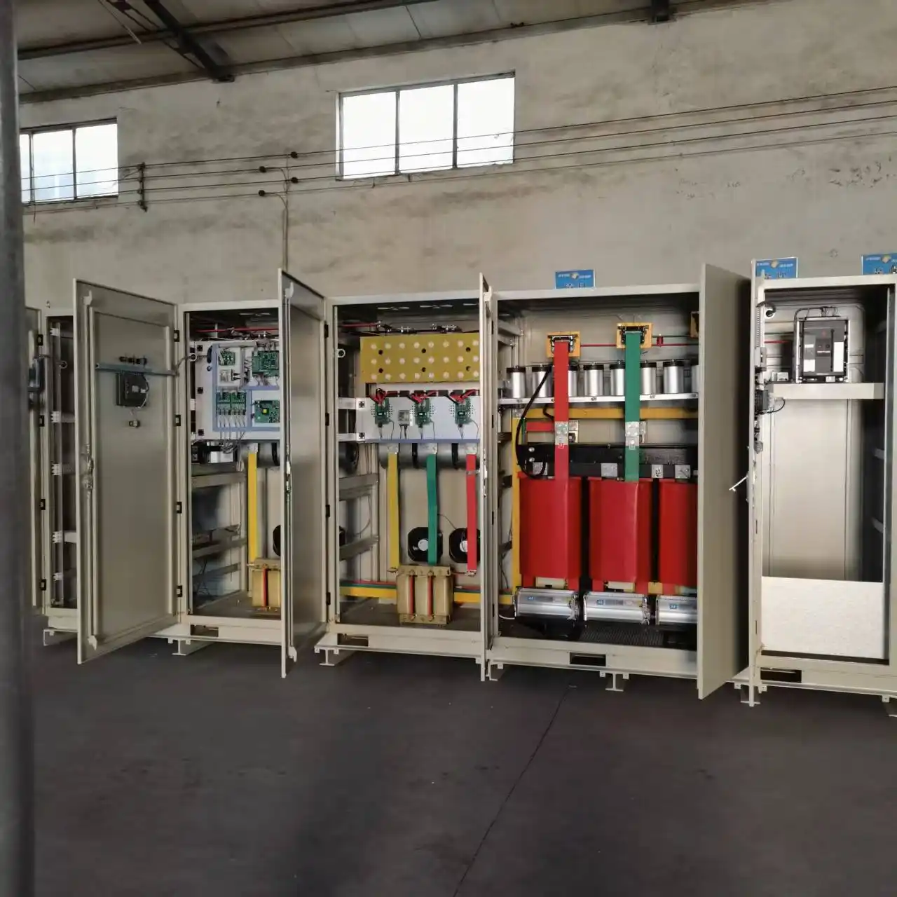
For high-voltage shore connection, IEC/IEEE 80005-1 includes control, monitoring, interlocking and power management within the HVSC system scope. IEC/IEEE 80005-3:2025 provides the corresponding framework for low-voltage systems within its defined application range.
Why Shore Power Control Needs More Than Start and Stop Commands
Connecting a vessel to shore power involves several electrical and operating states at the same time.
Depending on the project, a control decision may depend on:
- the selected berth and operating mode;
- breaker and isolating-device positions;
- converter readiness;
- shore-to-ship connection status;
- pilot or safety-circuit status;
- emergency-stop condition;
- vessel-side permission;
- protection status;
- the control location currently holding command authority.
The engineering challenge is not simply generating a command. It is proving that the system is in the correct condition for that command to be executed.
An operator can request breaker closing before every required condition has been established. A remote control room may have full visibility of the system without having command authority over a particular device. A logged-in user may be authorized to issue commands while an electrical permissive still blocks the operation.
These distinctions need to be defined in the control philosophy before they are turned into PLC logic.
This control layer sits inside the wider shore power system architecture . The operating sequence also has to match the actual shore power connection procedure .
Define the Operating Sequence Before Programming the PLC
The PLC program should implement an approved operating philosophy rather than become the only place where that philosophy exists.
Before programming starts, the operating states and the transitions between them need to be defined.
A project may, for example, distinguish between isolated, ready for connection, connected, energized, running, shutdown and fault states. The exact state model depends on the electrical architecture and operating procedure and should be developed from the actual project.
The same applies to cause-and-effect logic. The design needs to define:
- what conditions permit an operation;
- what conditions block it;
- what conditions initiate protective action;
- what must be restored before reset;
- what feedback proves that an operation has completed;
- what state is required after a failure.
That logic should be reviewable outside the PLC source code.
In one shore-power project, the operating sequence could be checked before live execution. The system supported online simulation, while individual operating steps were evaluated against predefined logic conditions. Execution status was also available as the sequence progressed.
This gives engineering, commissioning and operations teams a control philosophy that can be reviewed and tested before it is relied on in service.
From Permissive to Command to Confirmed State
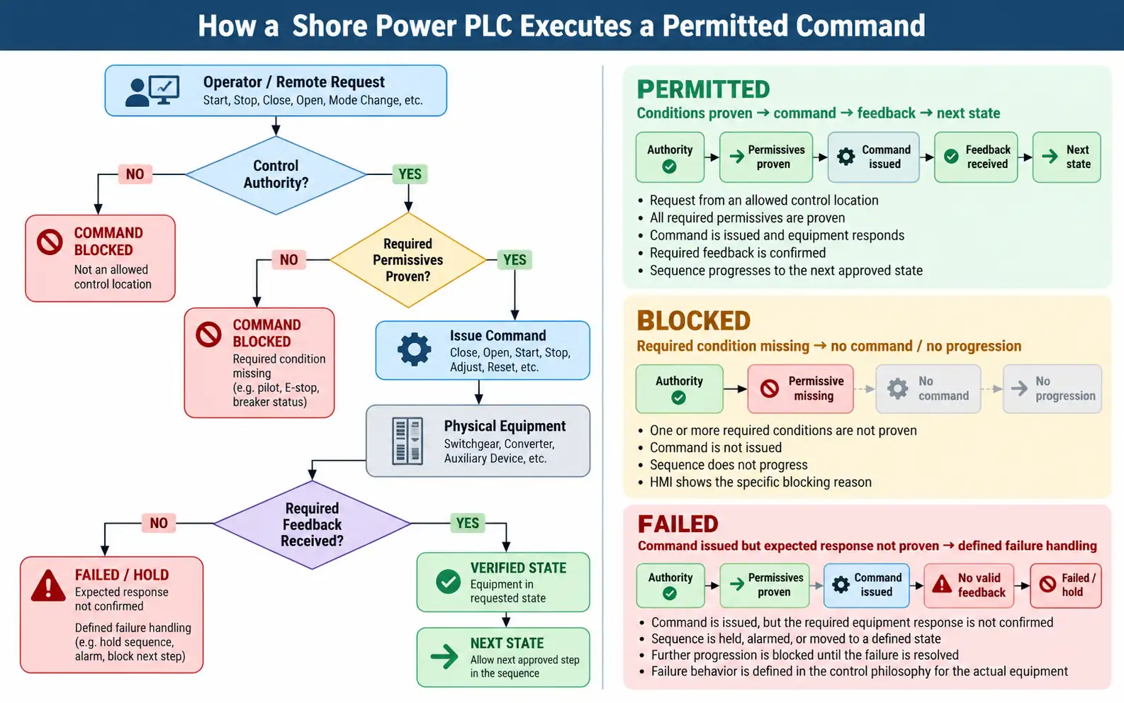
Check the Control Authority
Before evaluating equipment conditions, the system needs to know whether the request comes from an allowed control location.
A project may include local panels, a local HMI, a remote control room or other supervisory stations. The control philosophy should define where command authority resides and how that authority is transferred.
There is no universal rule that local or remote control must always take priority. The required hierarchy depends on the project operating philosophy.
Check the Required Permissives
A permissive is a condition that must be proven before a defined operation is allowed.
High-voltage shore connection provides clear examples. IEC/IEEE 80005-1 places interlocking and safety functions within the HVSC system framework.
Historical HVSC class guidance also illustrates how breaker operation can depend on conditions such as equipotential bonding, pilot status, emergency shutdown, connection-system condition and vessel-side permission. The exact requirements must be checked against the standards and class rules applicable to the project.
A command should not become an equipment action until the conditions defined for that action have been proven.
Issue the Command
Once authority and permissives are satisfied, the controller can issue the required command.
Depending on the architecture, that may include:
- starting or stopping the shore power source;
- closing or opening switchgear;
- resetting a controlled device;
- selecting an approved operating mode;
- operating an auxiliary function.
One project included local shore-power start/stop control, switchgear opening and closing, and an output-adjustment function. The exact control scope remains project-specific.
Confirm the Physical Response
Sending a command does not prove that the equipment reached the requested state.
A breaker-close command and a confirmed closed breaker are different pieces of information.
In one project, control commands were sent to connected control devices and the resulting execution status was returned to the supervisory system.
Where the sequence depends on the resulting equipment state, the required feedback should be confirmed before progression.
This becomes especially important when a device fails to operate, a position indication is incorrect, or the returned state does not match the requested action.
Allow the Next State — or Stop the Sequence
If the required state is confirmed, the sequence can move to the next approved step.
If a permissive is missing, the command remains blocked.
If a command has been issued but the required result is not confirmed, the control philosophy needs a defined response. Depending on the equipment and sequence, that may involve holding the sequence, alarming the failed action, blocking further progression, or moving to another defined state.
Feedback timeouts and failed-response behavior should be specified for the actual equipment and sequence rather than assumed from a generic PLC template.
The HMI Should Explain Why an Operation Is Blocked
Displaying voltage, current and frequency does not by itself make an HMI effective for control.
For operating decisions, the HMI should help the operator determine:
- the current operating state;
- which station has control authority;
- which important permissives have been proven;
- which condition is preventing the next action;
- whether the commanded equipment reached the required state;
- whether an active trip or fault is preventing reset or restart.
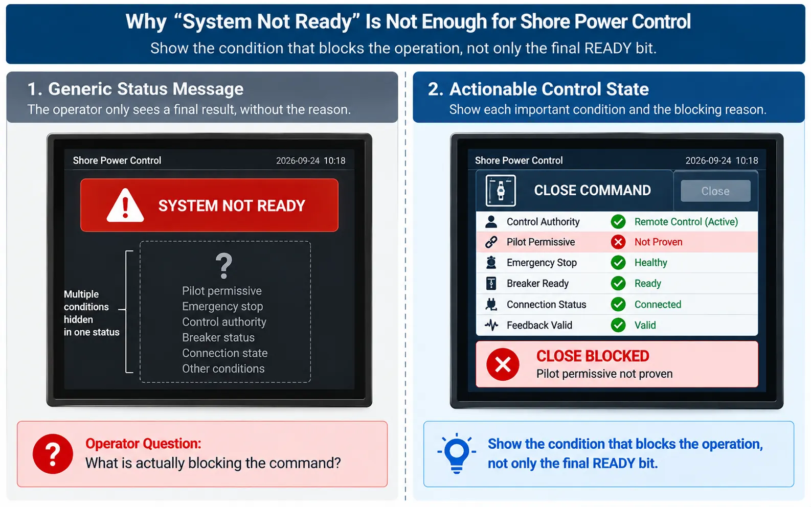
A message such as SYSTEM NOT READY does not identify the problem.
A message such as CLOSE BLOCKED — PILOT PERMISSIVE NOT PROVEN points the operator toward the condition requiring attention.
The objective is not to expose every PLC bit on the main screen. It is to make the control decision understandable.
General measurements, trends, energy records and SCADA visualization belong to the wider monitoring architecture. The PLC/HMI control view should concentrate on information needed to understand the operating state and current control decision.
Separate Control Authority, User Permission and Equipment Permissives
These concepts answer different questions.
| Control concept | Question it answers |
|---|---|
| Visibility | Can this user or station see the equipment state? |
| Authority | Which control location currently owns the command? |
| Permission | Is this user allowed to issue the command? |
| Permissive | Do the actual equipment and safety conditions allow the command? |
An operator can have permission to operate a breaker while the breaker-close command remains blocked because a required permissive is missing.
One shore-power project protected important operations with password authorization while recording system operations and parameter changes. The same control architecture used separate logic-condition checks during sequential operation.
User authorization therefore cannot replace electrical or safety logic.
Parameter access needs the same separation. A commissioning engineer may be authorized to change an operating parameter, but the permitted setting range should remain consistent with the approved equipment and operating modes.
Keep Protection and Supervisory Control as Distinct Layers
PLC control, electrical protection and safety circuits can exchange information without performing the same function.
Where a direct protective response is required:
The supervisory path serves another purpose:
In one HV shore-power project, loss of the equipotential-bonding circuit acted through a hardwired breaker path while the same condition was also passed to the PLC for system-level handling. The abnormal condition also prevented breaker closing and progression to the working position.
The international standards framework also distinguishes ordinary supervisory communication from emergency functions.
IEC/IEEE 80005-2:2016 covers shore-connection data communication for non-emergency monitoring and control functions, while emergency functions are addressed separately within the applicable shore-connection safety framework.
The control philosophy therefore needs to identify which functions require a dedicated protection or safety path and which functions can be coordinated by the supervisory controller.
Communication Loss Is a Control Problem, Not One Universal Trip Command
A communication failure does not have one correct response for every signal.
The first question is what function the communication path carries.
Loss of monitoring data is different from loss of remote command capability. Loss of a remote command path is also different from loss of equipment feedback that an active control sequence requires.
Depending on the architecture and affected function, the response may include:
- marking a value or state as unavailable;
- generating a communication alarm;
- blocking remote commands;
- retaining local operation where the architecture and affected function permit it;
- preventing sequence progression because required feedback is unavailable;
- relying on an independent safety or protection path for functions outside ordinary supervisory communication.
The required response needs to be defined in the control philosophy.
A specification that simply states COMMUNICATION LOSS = TRIP without identifying the affected function may be just as incomplete as one that ignores communication loss entirely.
Control Errors Can Become Physical Equipment Problems
PLC logic is software, but the equipment it controls is physical.
In one shore-power project, current was measured by CTs and passed to the PLC so that an auxiliary switching function could respond to the actual operating condition.
In that application, delayed switching could leave a current-limiting resistor exposed longer than intended and create a risk of damage. Control logic, field verification and hardware measures were therefore used together.
When a physical process depends on timing or state, the control logic needs to be verified against that physical process.
Additional automation is useful only when its inputs, feedback, timing and failure responses can be defined and tested.
The related transformer energization issue is discussed separately in our shore power transformer inrush-current article .
Test the Logic in Permitted, Blocked and Failed States
Functional FAT should verify three different conditions.
Permitted State
Verify that the command is accepted, the controlled device responds, the required feedback is received and the sequence reaches the intended next state.
Blocked State
Remove or simulate a required condition and confirm that the command or sequence progression is rejected as defined.
Failed State
Simulate relevant equipment, feedback or communication failures and confirm that the sequence follows the defined abnormal-state response.
A blocked-state test may involve a missing connection permissive, an active emergency-stop condition, unavailable command authority or missing equipment feedback.
Failed-state testing may involve:
- a controlled device failing to respond;
- loss of a relevant communication path;
- unexpected or conflicting feedback;
- a protection trip during the sequence;
- restoration of control power and subsequent recovery.
The expected response should be agreed before the test is performed.
One factory test checked PLC-to-controller communication together with physical electromagnetic locking and energized-state interlocks.
In one vessel-connection procedure, the safety-interlock circuit was also checked after cable connection and before shore power was energized.
Testing the PLC while ignoring the physical device is not enough. The acceptance plan should consider the complete path from command to equipment response and returned state.
Functional control testing should therefore form part of the wider shore power manufacturing and FAT process .
What to Define Before PLC and HMI Programming Starts
“PLC and HMI required” is not a control specification.
Before programming starts, enough project information is needed to define what the control system is expected to coordinate.
Electrical Architecture
- single-line diagram;
- equipment list;
- voltage and frequency modes;
- berth arrangement;
- controlled switchgear and auxiliary equipment.
Operating Philosophy
- startup;
- vessel connection;
- energization;
- transfer, where applicable;
- normal shutdown;
- fault, recovery and restart states.
Cause-and-Effect
- required permissives;
- blocking conditions;
- trip inputs;
- reset conditions;
- required field feedback.
Control and Interfaces
- local and remote control stations;
- authority-transfer rules;
- operator roles;
- field I/O and required feedback;
- protection and safety interfaces;
- communication requirements;
- FAT and SAT scenarios.
These inputs allow the PLC/HMI scope to be reviewed against the complete shore power system before programming begins.
Frequently Asked Questions
What does a PLC control in a shore power system?
The PLC or supervisory controller coordinates the functions allocated to it, which may include sequence control, equipment commands, permissive evaluation, feedback handling and auxiliary control. The exact scope depends on the electrical architecture and control philosophy.
What is a permissive in shore power control?
A permissive is a proven condition that must be satisfied before a specific operation is allowed. A user may have permission to issue a command while the equipment permissive still blocks it.
Is the HMI part of the protection system?
Not automatically. The HMI can display protection status and issue operating commands within its control scope, while protective or emergency actions may be performed by dedicated relays, hardwired circuits or other safety functions defined for the project.
Can a shore power system be controlled remotely?
Yes, when remote control is included in the architecture. The design should define command authority, authority transfer, applicable permissives and the response when a required communication path is unavailable.
What should happen if PLC or SCADA communication is lost?
It depends on the function affected by that communication. Loss of monitoring, remote command capability and equipment feedback can require different responses. The required behavior should be defined in the control philosophy rather than assumed from one universal trip rule.
Why should blocked sequences be tested during FAT?
Because the control system has to demonstrate that it rejects an operation when required conditions are missing, not only that it completes the normal sequence when all conditions are healthy.
Define the Control Philosophy Before Programming
The PLC program should implement an agreed control philosophy rather than become the place where the project first determines how the system is supposed to operate.
Send the single-line diagram, equipment list, operating modes, vessel connection and transfer sequence, cause-and-effect requirements, local and remote control locations, protection interfaces and communication requirements.
We can review the PLC and HMI scope against the shore-power electrical architecture and identify the permissives, field feedback and FAT scenarios that need to be defined before programming.
Send Your Control RequirementsTechnical References
- IEC/IEEE 80005-1:2019 + AMD1:2022 + AMD2:2023 — High-voltage shore connection systems.
- IEC/IEEE 80005-2:2016 — Data communication for high- and low-voltage shore connection monitoring and control.
- IEC/IEEE 80005-3:2025 — Low-voltage shore connection systems.
- ABS Rules for Building and Classing Marine Vessels, Part 6, Chapter 4 — Low and High Voltage Shore Connection.
