
Why a THD Number Can Be Misleading
Consider two reports that both state Voltage THD = 2%. They may still describe completely different engineering conditions.
One result may come directly from the frequency converter output at rated load. Another may be taken after an output transformer and a long shore cable at partial load. One may come from a factory load-bank test. The other may be measured at the final shore connection during commissioning.
Even when the numerical value is identical, the electrical meaning is not necessarily identical.
| Question | What needs to be defined |
|---|---|
| Where was it measured? | The exact measurement point on the single-line diagram. |
| Under what operating condition? | Voltage, frequency, load, power factor and system configuration. |
| How was it measured? | Instrument, sensors, measurement method, settings and calibration status. |
| What was it compared against? | The applicable contractual, project or acceptance criterion. |
The purpose of defining these conditions is not administrative paperwork. It prevents technically different measurements from being treated as though they were directly comparable.
Define the Measurement Point Before Testing
The port grid, converter input, converter output, transformer secondary, shore connection point and vessel inlet are different electrical locations. They should not be treated as interchangeable measurement points.
At the converter input, current harmonics are influenced by the upstream supply, input-transformer arrangement and converter topology. At the converter output, the voltage waveform represents converter-side performance before the complete downstream electrical path has been added.
Farther downstream, transformers, filters where installed, switchgear, cable impedance and the connected load can change what is observed.
The measurement point should therefore be marked on the single-line diagram before testing begins. The record should identify the voltage level, circuit configuration and whether voltage is measured phase-to-phase or phase-to-neutral.
A clean converter-terminal waveform is useful evidence. It is not, by itself, proof that the same waveform will exist at the vessel connection after the final transformer and cable path.
For the wider engineering mechanisms behind distortion, see our shore power harmonics and power quality guide.

THDu, THDi and Individual Harmonics Answer Different Questions
Voltage distortion and current distortion should not be combined into one general “harmonic performance” number.
THDu, sometimes written as voltage THD or THDv, describes total harmonic distortion in the voltage waveform.
THDi describes harmonic distortion in the current waveform. Current distortion is strongly influenced by the connected load. Voltage distortion is affected by the interaction between harmonic current and the impedance of the electrical system.
A system can therefore show relatively low voltage distortion while its current waveform contains more harmonic content. The two measurements answer different questions.
Where the project specification defines limits for individual harmonic orders, those values should also be reviewed. An acceptable total distortion value does not automatically prove that every individual harmonic satisfies a separate requirement.
Why the Test Load Matters
The load bank is part of the test boundary.
A harmonic test made at no load does not prove the same behavior at partial or rated load. Likewise, a test made with one artificial load arrangement does not automatically reproduce every vessel load characteristic.
Example From a Shore Power Project Test Arrangement
One project test setup included resistive and inductive loading capability, controlled loading functions, data acquisition and electrical monitoring. The documented equipment included defined loading accuracy, phase-balance capability and Class 0.5 parameter measurement for the stated test arrangement.
These characteristics describe that project test system. They should not be treated as universal load-bank specifications.
A controlled resistive/inductive load bank is valuable during FAT because it allows the test team to repeat defined operating points and load transitions.
However, an actual vessel can contain a different combination of motors, drives, rectifiers, hotel loads, pumps and other nonlinear or dynamic loads.
Incorrect conclusion: Every possible vessel will produce exactly the same harmonic result.
A Harmonic Test Is Part of a Controlled Test Sequence
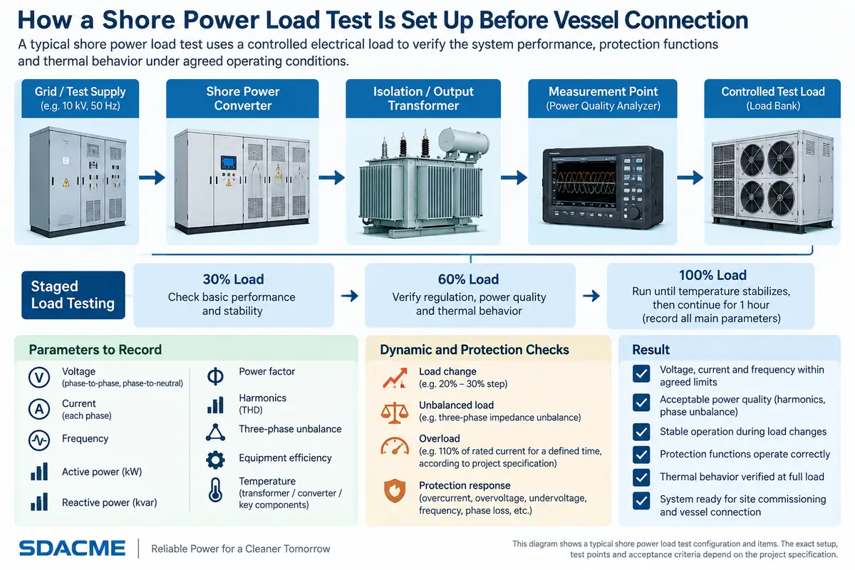
Shore power waveform testing should not be treated as an isolated analyzer reading. The electrical configuration, test equipment and operating condition have to be established first.
A useful verification sequence moves from configuration confirmation through controlled energization, steady-state measurement, dynamic events and finally traceable reporting.
This sequence matters because a waveform without the event and operating condition that produced it can be difficult to interpret later.
The project documentation used for this engineering review required waveform recording during the relevant load-test process so that the test remained traceable.
Why One Load Point Is Not Enough
Harmonic performance does not have to remain constant across the entire operating range. Converter operating state, current magnitude, connected load composition, power factor and network impedance can all influence what is measured.
That is why one light-load or rated-load result should not automatically be used to describe the complete operating envelope.
Project Test Example
One project procedure used 30%, 60% and 100% of rated capacity as defined test points.
The recorded parameters included voltage, current, frequency, active power, reactive power, power factor, harmonics, three-phase imbalance and system efficiency. At full load, operation continued after thermal stabilization for an additional hour.
These percentages and durations are project-specific test conditions, not universal shore power requirements.
The engineering principle is more general: the operating point belongs beside the harmonic result.
A test report becomes more useful when it shows whether the system remains acceptable through the required operating range rather than presenting a single isolated THD figure.
Capture More Than Steady-State THD
Steady-state harmonic measurement answers only one part of the acceptance question. It describes waveform quality after the electrical system has reached a stable operating condition.
It does not fully describe what happens when a significant load is connected or removed.
During a load transition, the test may need to observe:
- initial RMS voltage and frequency;
- applied or removed load step;
- voltage deviation;
- frequency deviation;
- voltage and current waveform disturbance;
- recovery behavior;
- final stabilized condition.
In one project procedure, output waveform testing included switching a load group equivalent to approximately 30% of rated capacity. Another site test plan used an approximately 20–30% load adjustment while checking output-voltage waveform distortion and voltage/frequency transient recovery.
Those percentages should not be converted into a universal shore power rule. The required load transition should follow the project's approved operating case, test equipment and acceptance procedure.
For a deeper treatment of dynamic performance, see our shore power overload and step-load testing guide.
Low THD Does Not Automatically Mean Good Dynamic Performance
Three separate performance questions should be distinguished.
Steady-State Waveform Quality
Does voltage or current harmonic distortion meet the required criterion under the defined stabilized operating condition?
Voltage & Frequency Regulation
Does the shore power output remain within the required operating range while the connected load changes?
Transient Recovery
After a defined disturbance or load transition, how quickly and cleanly does the system recover?
These behaviors interact, but they are not interchangeable.
A converter can produce a clean steady-state waveform and still require investigation if voltage dip, frequency deviation or recovery time is unacceptable after a load transition.
Likewise, fast recovery does not prove that steady-state harmonic distortion satisfies the required criterion.
Test 50 Hz and 60 Hz Modes as Separate Operating Cases When Required
Many shore power systems need to serve vessels using different electrical standards. A project may, for example, require both 400 V / 50 Hz and 440 V / 60 Hz.
Where both modes are part of the contractual scope, they should be included as separate verification cases unless the approved project test plan establishes another method.
A change in operating mode can involve different converter control conditions, transformer configuration or downstream electrical behavior.
The active voltage and frequency mode should be recorded together with the harmonic and waveform results.
How to Read a Real Project Test Result
Real test evidence is useful only when its boundary is preserved.
Recorded Project Result
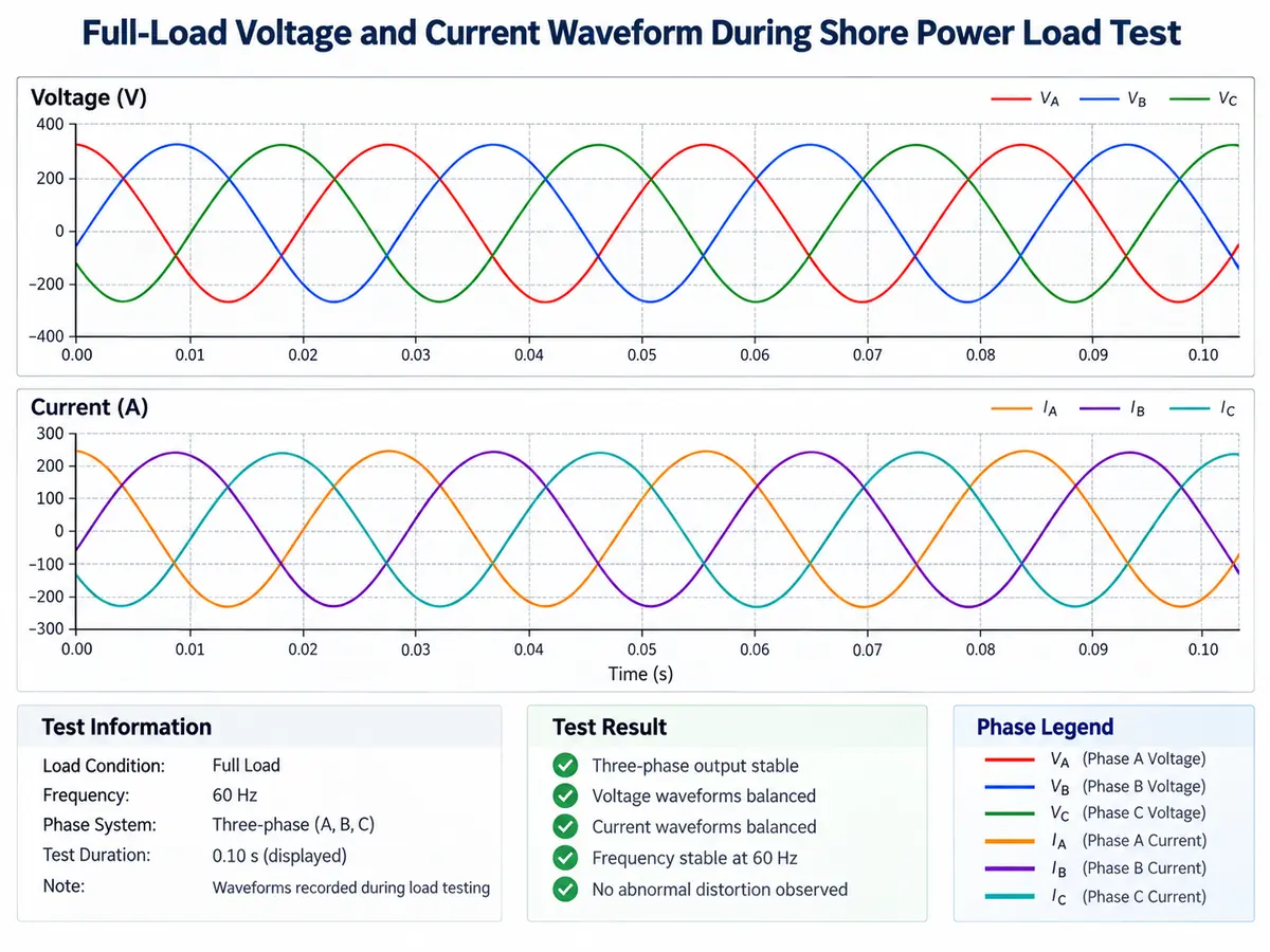
A shore power project test record includes a full-load voltage and current waveform and reports a maximum voltage harmonic distortion of approximately 1.88% and voltage imbalance not exceeding 0.1% under the documented test condition.
These figures demonstrate the performance of that tested configuration. They do not establish a universal product value for every shore power system.
To understand what the 1.88% result actually proves, an engineer still needs to know:
- which equipment configuration was operating;
- where the measurement was taken;
- which load was connected;
- which voltage and frequency mode was active;
- which measurement method was used;
- which acceptance criterion applied.
If these conditions change, the number may no longer describe the same electrical case.
Acceptance Criterion and Measured Result Must Stay Separate
A credible test report distinguishes between what the project requires and what the system actually measured.
In one project technical schedule used as engineering evidence for this article, the specified values included:
- Output-voltage waveform THDu ≤ 2%
- Input-current THDi ≤ 3%
A separate project test record reported a maximum voltage harmonic distortion of approximately 1.88% under its documented test condition.
| Evidence layer | What it means |
|---|---|
| Project criterion | The acceptance requirement defined for the specific project. |
| Test boundary | The system configuration, measurement point and operating condition. |
| Measured result | The actual value recorded during the test. |
| Engineering decision | The measured result compared with the applicable criterion. |
| Publication boundary | The result should not be generalized beyond the tested configuration. |
This structure is much stronger than publishing a standalone statement such as “THD = 1.88%”.
From Analyzer Reading to Traceable Evidence
A screenshot can be useful for visual confirmation, but it should not be the only surviving evidence.
A complete test record should allow another engineer to reconstruct what happened. That means linking the numerical result to the single-line diagram, instrument setup, test load, event timing and approved criterion.
The test record should identify, as applicable:
- analyzer manufacturer and model;
- serial number;
- voltage probes or measurement-transformer path;
- current sensor or CT path;
- calibration status;
- measurement class where required;
- wiring arrangement;
- measurement and aggregation settings;
- test date and operating mode;
- load condition and event timing.
If a result is repeated after a setting or configuration change, the report should state what changed. Otherwise the two results cannot be compared reliably.
Build Harmonic Testing Into the FAT Record
Harmonic testing is one part of the wider factory acceptance process. Its results should remain connected to the approved test procedure and final FAT decision.
A useful FAT package can include:
- approved test procedure;
- single-line measurement location;
- converter and transformer configuration;
- output voltage and frequency mode;
- instrument and calibration information;
- load-bank configuration;
- steady-state load points;
- dynamic load-change records where required;
- harmonic tables;
- raw waveform files;
- deviation and retest records;
- final acceptance decision.
For the wider factory-verification sequence, see shore power manufacturing and FAT .
FAT and SAT Answer Different Questions
Factory Acceptance Testing and Site Acceptance Testing are related, but they do not necessarily test the same electrical boundary.
| Engineering factor | FAT | SAT / Final Installed Test |
|---|---|---|
| Main purpose | Verify equipment or packaged-system behavior under controlled conditions. | Verify the installed system in the final site environment. |
| Load | Usually controlled load bank. | Approved site load or final commissioning arrangement. |
| Electrical path | Factory test configuration. | Final switchgear, transformers, berth cables and connection equipment. |
| Measurement point | Defined factory test terminal. | Project or contractual site acceptance point. |
| Environment | Controlled factory conditions. | Actual installed port environment. |
| Vessel influence | Usually simulated or absent. | May include final vessel interface or site commissioning load. |
A FAT and SAT result can therefore differ without either result automatically being wrong.
Before diagnosing the difference, compare the test boundaries first.
How to Diagnose an Abnormal Harmonic or Waveform Result
Case 1 — THDi Is High at the Converter Input
First confirm that the quantity is current distortion and that the measurement point is actually upstream of the converter. Then review the operating load, sensor path, measurement setup and converter/input-transformer topology before concluding that equipment performance is unacceptable.
Case 2 — Converter Output Looks Good but Shore-Connection Voltage Is Worse
Compare the downstream electrical path. Transformer characteristics, filters where installed, switchgear, cable impedance and the connected load can influence the voltage measured farther downstream.
Case 3 — THD Passes but the Load-Step Test Does Not
Treat this as a dynamic-performance issue. Steady harmonic compliance and transient voltage/frequency recovery are separate acceptance questions.
Case 4 — FAT and SAT Results Do Not Agree
Before changing equipment settings, compare measurement point, load, voltage/frequency mode, transformer and cable path, instrument method and acceptance criterion. Only after those conditions are aligned should the difference be attributed to equipment performance.
What Harmonic Testing Does Not Prove
A harmonic test is important, but its scope should not be overstated.
An acceptable THDu result does not by itself prove:
- correct protection operation;
- insulation withstand performance;
- reverse-power protection behavior;
- acceptable performance with every possible vessel;
- acceptable dynamic response unless that condition was tested;
- performance of the complete installed berth-to-vessel path if it was not included in the test boundary.
Each acceptance test answers a defined engineering question. The strongest acceptance program is therefore not the one with the largest number of screenshots, but the one in which every result has a clear boundary, criterion and record.
Common Reasons Harmonic Test Reports Become Weak Evidence
Information Needed to Prepare a Harmonic and Waveform Test Plan
A useful test plan begins with the actual project electrical configuration, not a generic THD target.
- Single-line diagram
- Rated shore power capacity
- Input voltage and frequency
- Required output voltage and frequency modes
- Converter arrangement
- Transformer arrangement
- Proposed measurement points
- Contractual harmonic criteria
- THDu requirements
- THDi requirements
- Individual harmonic requirements where applicable
- Voltage tolerance
- Frequency tolerance
- Voltage-imbalance criterion
- Available load-bank capacity
- Resistive/reactive loading capability
- Required steady load points
- Required load transitions
- Expected power factor
- Instrument / measurement-class requirements
- Stabilization duration
- FAT and SAT boundaries
- Raw-data and report-format requirements
The objective is not to force every shore power project into one fixed test template. It is to ensure that the test plan matches the actual system and acceptance boundary.
Frequently Asked Questions
What is the difference between THDu and THDi?
THDu describes harmonic distortion in the voltage waveform. THDi describes harmonic distortion in the current waveform. They are different quantities and should always be associated with a defined measurement point and operating condition.
Is a no-load waveform test sufficient?
No. It can confirm basic converter operation, but it does not demonstrate harmonic performance across the required loaded operating conditions.
Where should shore power THD be measured?
Use the measurement point defined by the project test and acceptance boundary. Additional converter-side measurements can help distinguish converter performance from downstream transformer, cable or load effects.
Do all shore power projects need 30%, 60% and 100% load tests?
No. Those values come from a specific project test procedure used as engineering evidence for this article. The actual load schedule should follow the approved requirements of the specific project.
Is 1.88% THDu a standard SDACME specification?
No. It is a recorded result from a particular project test condition and should not be treated as a universal product limit or guarantee.
Why can SAT results differ from FAT results?
Because the electrical boundary can be different. SAT may include final transformers, switchgear, berth cables and the installed shore connection that were not identical to the factory test configuration.
Can a load bank reproduce every vessel load?
No. A controlled load bank provides repeatable testing, but the actual vessel can contain a different mixture of linear, nonlinear and dynamic loads.
Can low THD compensate for poor transient response?
No. Steady-state harmonic distortion and transient voltage/frequency recovery answer different acceptance questions.
Should 50 Hz and 60 Hz modes be tested separately?
Where both modes are required by the project, they should be included in the approved verification plan rather than assuming that one operating mode represents the other.
Technical Reference Framework
The following standards provide relevant power-quality measurement and shore-connection frameworks. Actual acceptance criteria should still come from the applicable contract, technical specification and approved project test procedure.
Electromagnetic compatibility (EMC) — Part 4-30: Testing and measurement techniques — Power quality measurement methods.
Electromagnetic compatibility (EMC) — Part 4-7: General guide on harmonics and interharmonics measurements and instrumentation.
Power quality measurement in power supply systems — Part 1: Power quality instruments (PQI).
Utility connections in port — High-voltage shore connection systems — General requirements.
Utility connections in port — Low-voltage shore connection systems — General requirements.
Define the Test Boundary Before Comparing Results
The most useful question is not simply: “What is the THD?”
It is: “What does this result prove under this defined test condition?”
If you are preparing a shore power FAT, commissioning test or power-quality acceptance plan, send the single-line diagram, rated power, voltage/frequency modes, proposed measurement points, harmonic criteria and available test-load information.
SDACME can review the test boundary and help organize a repeatable harmonic and waveform verification plan around the actual shore power configuration.
Send Your Power-Quality Test Requirements