
How Shore Power Systems Control Harmonics and Output Power Quality
A shore power system has to deliver more than the correct voltage and frequency.
The quality of the waveform also matters, especially when the system operates with changing, unbalanced or nonlinear vessel loads. Harmonics can appear on both sides of the frequency converter, and the conditions that affect the port grid are not necessarily the same as those that affect the voltage delivered to the vessel.
For this reason, shore power quality should not be judged from one advertised THD value alone. The measurement point, load condition, grid strength and complete conversion path all need to be defined.
Shore power harmonics should be evaluated separately on the grid side and the vessel side.
On the shore-grid side, the phase-shifting transformer, rectifier topology and upstream network impedance influence the harmonic current drawn by the converter and the resulting voltage distortion at the point of connection.
On the vessel side, the inverter, multilevel PWM topology, transformers, filtering and connected vessel loads influence the output voltage waveform, phase balance and dynamic response.
A meaningful power-quality specification therefore needs to answer three questions: Where is the measurement made? Under what operating condition is it measured? What acceptance limit must the complete system meet?
Input Harmonics and Output Harmonics Are Not the Same
On the input side, the frequency converter draws current from the shore grid.
A rectifier can draw current in pulses rather than as a perfect sinusoidal waveform. These current harmonics flow into the upstream network, where their effect depends not only on the converter but also on grid strength, transformer impedance and other connected equipment.
A strong network with relatively low source impedance may experience less voltage distortion from a given harmonic current than a weaker network.
On the output side, the inverter reconstructs an AC waveform for the vessel. Pulse-width modulation, converter topology, transformer characteristics and filtering all influence the quality of this output waveform.
This distinction matters when specifications are compared. An input current THD value does not prove the quality of the output voltage waveform. Likewise, a clean vessel-side voltage waveform does not show how much harmonic current the shore system is drawing from the port network.
A project specification should therefore identify both the quantity being measured and the exact measurement location.
How Phase Shifting Helps Reduce Input Harmonics
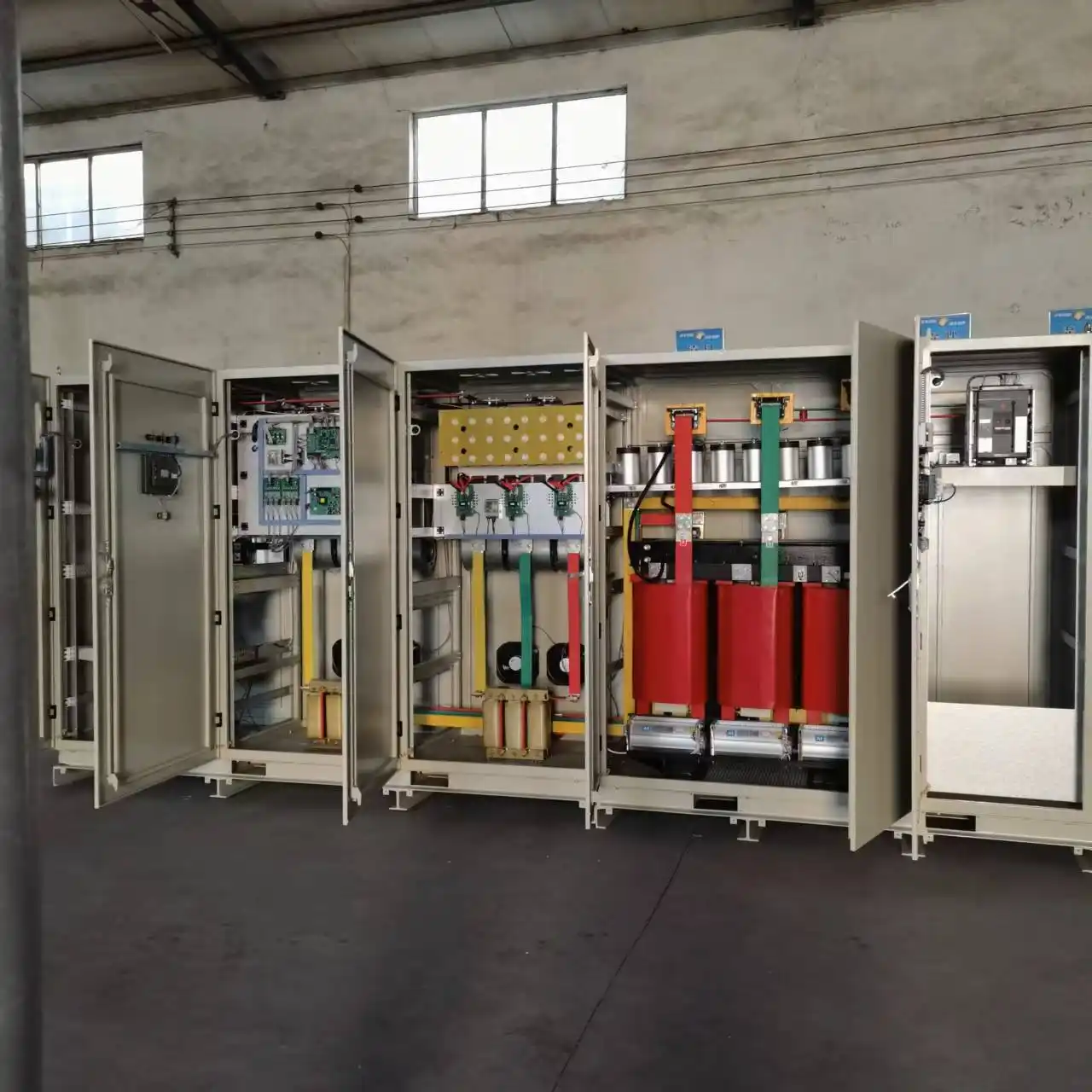
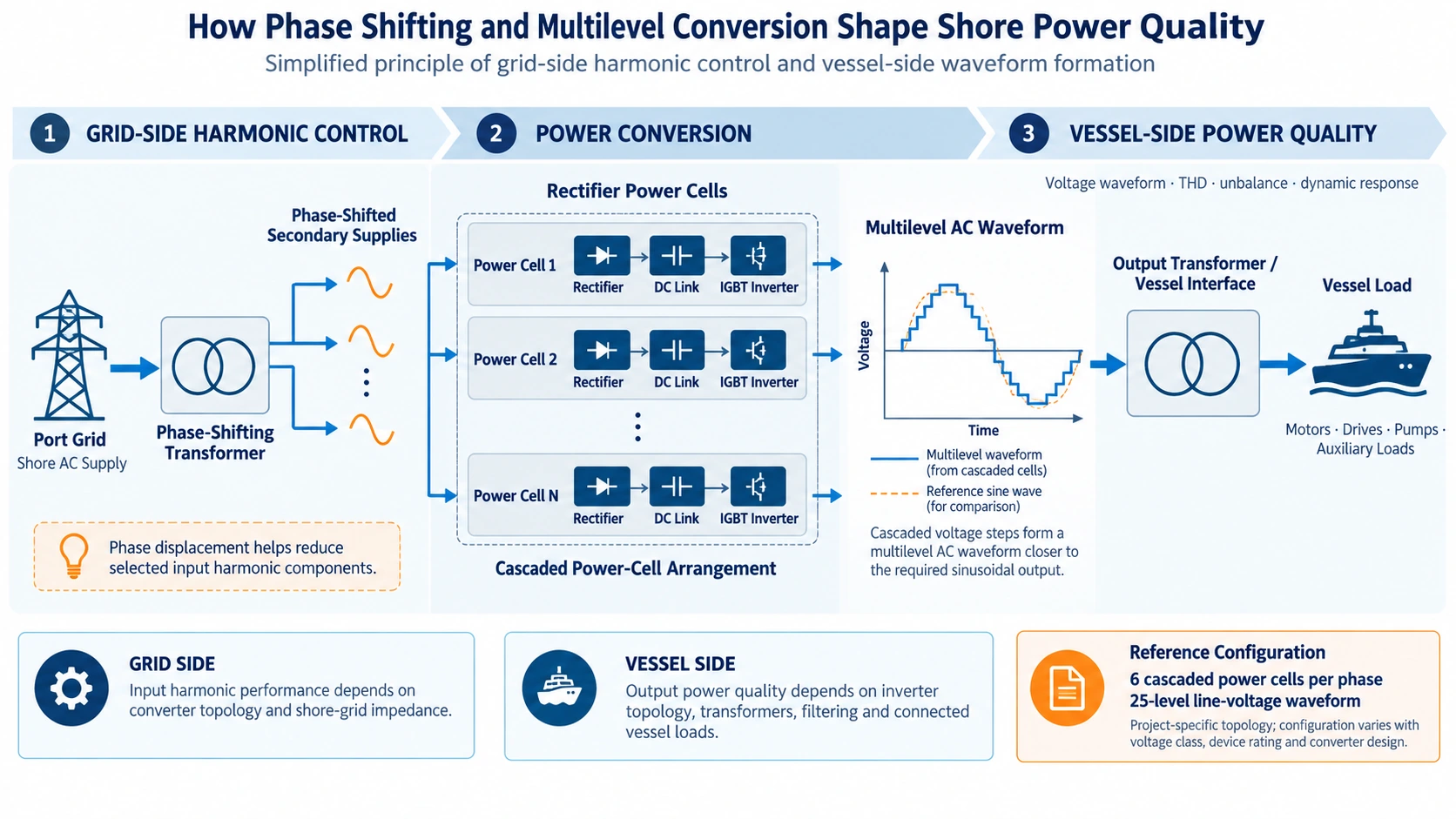
In a cascaded multilevel shore power configuration, a phase-shifting transformer can provide multiple secondary supplies with defined phase relationships for the rectifier power cells.
When the rectifier currents from these secondary windings are combined on the transformer primary side, selected harmonic components can cancel or be reduced.
Each power cell receives its required secondary supply, rectifies the AC input to a DC link and then uses the inverter stage to produce a controlled output.
The number of secondary windings, phase displacement and power-cell arrangement depend on the selected converter topology, voltage class, capacity and harmonic target. These parameters should therefore be engineered for the project rather than copied directly from another installation.
For more detail on the conversion equipment, see our marine frequency converter page.
Multilevel PWM Shapes the Output Waveform
Inside the converter, IGBT power cells switch their DC-link voltages using pulse-width modulation.
When several cells are connected in a cascaded arrangement, their individual voltage steps combine to form a multilevel output waveform. Smaller voltage steps can help the combined waveform approach a sinusoidal shape more closely before the final vessel-side transformation and filtering stages.
In one documented high-voltage shore power reference configuration, six cascaded power cells were used per phase.
In that configuration, the combined converter output produced a 25-level line-voltage waveform before the final vessel-side stage.
These figures describe that particular reference topology. They are not fixed design values for every shore power converter. Cell quantity and voltage levels depend on the required system voltage, semiconductor device rating and converter architecture.
The more useful procurement question is therefore not simply whether the converter uses multilevel PWM, but what power-quality performance is specified at the defined measurement point and operating condition, and how that performance will be verified.
Grid Strength Changes the Result at the Point of Connection
The same frequency converter can produce different system-level power-quality results when installed at two different ports.
The reason is that the converter is only one part of the electrical network.
A strong shore grid normally has lower source impedance and is less affected by a given harmonic current. A weaker grid may experience greater voltage distortion from the same converter current.
Transformer impedance and long cable runs add further impedance to the system. Existing capacitor banks, large drives and other nonlinear loads can also interact with the harmonic environment.
Filters and capacitors should therefore not be considered in isolation. Under certain network conditions, impedance and capacitance can interact and create resonance concerns that would not be visible from the converter datasheet alone.
For a meaningful network review, the port should provide the available short-circuit capacity or equivalent source-impedance information at the proposed connection point.
Without this information, converter performance can still be discussed, but the effect of the complete installation on the port network cannot be fully evaluated.
Vessel Loads Create Their Own Power-Quality Demands
A vessel is not a constant resistive load.
Pumps, fans, compressors, hydraulic systems, rectifiers, variable-speed drives and other electrical equipment can create rapid load changes, nonlinear current and phase unbalance.
When a large motor starts, the most important power-quality issue may not be steady-state harmonic distortion at all. The main concern may instead be the size of the voltage dip and how quickly the shore power system recovers.
With nonlinear vessel loads, current distortion may be relatively high even while the shore-side voltage remains within the specified range.
Unbalanced loads introduce another requirement: the converter and downstream electrical system must maintain acceptable phase voltages when the three phases are not equally loaded.
For this reason, average vessel kW is not enough to define the operating condition. The project review should also consider the largest motor, its starting method, major nonlinear equipment, expected load steps and the permitted vessel-side voltage and frequency range.
Our shore power selection and compatibility guide explains the vessel and grid information normally required before the final configuration is confirmed.
What Should Be Measured During a Shore Power Load Test?
Power-quality results are useful only when the operating condition is recorded together with the measurement.
Depending on the agreed FAT or acceptance procedure, typical measurements can include:
- Input and output voltage
- Input and output current
- Frequency
- Active and reactive power
- Power factor
- Voltage and current harmonic distortion
- Three-phase voltage and current unbalance
- Efficiency where included in the agreed procedure
- Voltage and frequency response during load changes
Steady-state and dynamic measurements answer different questions. A harmonic measurement at a stable load shows waveform quality under that condition, while a load-step test shows what happens when vessel demand changes quickly.
Both may be necessary when power quality is part of the acceptance criteria.
Reference Power-Quality Test Results
One documented shore power test procedure used staged operation at 30%, 60% and 100% load. Full-load operation continued after temperature stabilization, and waveform measurements were recorded as part of the test.
The same reference also included a 20%–30% load-change test to observe system response under changing demand.
| Maximum voltage THD | 1.88% |
|---|---|
| Voltage unbalance | ≤0.1% |
| Staged load points | 30% / 60% / 100% |
| Load-change range | 20%–30% |
These results belong to the referenced test configuration and test conditions. They are not universal performance guarantees for every SDACME shore power system. Project acceptance limits should be defined separately in the technical agreement and FAT procedure.
Harmonic Limits Need a Defined Boundary
The project should state whether the requirement applies to input current, input voltage, converter output voltage, vessel connection voltage or another specified measurement point.
It should also define the loading condition, measuring instrument, observation period and whether limits apply only to total harmonic distortion or also to individual harmonic orders.
This prevents two technically different measurements from being compared as if they were the same specification.
For example, an input-current THD measured at the converter feeder should not be compared directly with an output-voltage THD measured after a transformer at the vessel connection.
Applicable standards and classification requirements can provide part of the framework, while the exact edition, measurement boundary and project acceptance criteria still need to be confirmed.
Our shore power standards and compliance page explains how the IEC/IEEE 80005 framework and project-specific requirements fit into the overall shore power design.
Common Power-Quality Mistakes
Comparing THD Values Measured at Different Locations
Two THD values are not directly comparable when one is measured on the converter input and another at the vessel-side output. The measured quantity and location must be identified first.
Treating a No-Load Waveform as Proof of Full-Load Performance
A no-load waveform can confirm basic converter operation, but it does not show how the complete system behaves under representative vessel load. Transformer impedance, converter loading and nonlinear vessel equipment can change the operating result.
Selecting Filters Before the Shore Network Is Understood
An input filter should not be finalized without sufficient information about the port network. Existing capacitor banks, transformer impedance, cable impedance and network conditions can interact with the proposed filtering arrangement.
Checking Harmonics but Ignoring Motor Starting
A system may satisfy a steady-state harmonic requirement and still experience an unacceptable voltage dip when a large vessel motor starts. Power-quality review should therefore include dynamic events where they are relevant to the vessel load profile.
Treating the Converter as an Isolated Component
The final waveform seen by the vessel also depends on transformer characteristics, cable length, impedance and the connection arrangement. Power quality is a system result, not only a converter specification.
Information Needed for a Shore Power Quality Review
Before the converter configuration and acceptance criteria are finalized, provide:
- Shore-grid voltage and frequency
- Available short-circuit capacity or network impedance
- Existing transformers and capacitor banks
- Major nonlinear shore loads
- Required converter capacity
- Vessel voltage and frequency
- Maximum vessel load
- Largest motor and starting method
- Expected load steps
- Major nonlinear or unbalanced vessel loads
- Required harmonic measurement point and limits
- Applicable standards or classification requirements
- Required FAT and site-test scope
With these inputs, the converter, transformers, network interfaces and test plan can be reviewed as one power-quality system rather than as separate pieces of equipment.
Frequently Asked Questions
What is the difference between current THD and voltage THD?
Current THD describes distortion in the current drawn or supplied by electrical equipment. Voltage THD describes distortion of the voltage waveform at a defined point. Network impedance links current distortion and voltage distortion, but one value cannot replace the other.
Does a phase-shifting transformer eliminate all harmonics?
No. A phase-shifting transformer can help cancel or reduce selected harmonic orders when used with the intended rectifier and converter arrangement. The final result still depends on transformer design, converter topology, loading and shore-grid conditions.
Can output THD be checked without load?
A no-load measurement is useful for basic verification, but it does not replace measurements under representative operating load. Where power quality forms part of acceptance, the required load condition should be stated in the FAT or other approved test procedure.
Why is port short-circuit capacity needed?
Short-circuit capacity provides information about grid strength at the proposed connection point. The same harmonic current can produce different levels of voltage distortion when connected to networks with different source impedances.
Should harmonic testing include load steps?
Steady-state harmonic performance and transient response are different tests. A complete power-quality review may therefore include both harmonic measurements at defined operating points and voltage/frequency response during representative load changes.
Discuss Your Shore Power Quality Requirements
Send us the shore-grid data, vessel load list, largest motor, required measurement boundary and applicable power-quality limits. We can review the input harmonic arrangement, output waveform, transformer interfaces, grid conditions and proposed FAT criteria before the shore power converter configuration is finalized.
Send Your Electrical Data