
How to Limit Transformer Inrush Current in Shore Power Systems
Transformer inrush current can trip a shore power converter even when the vessel transformer has no load connected.
The current appears when an unenergized transformer is switched onto the supply. Its magnitude depends on the switching instant, residual core flux, transformer construction and source impedance.
In a converter-fed shore power system, this short-duration event matters because the frequency converter has defined semiconductor current limits, current-control behavior and protection thresholds.
The transformer, converter, switching sequence and protection therefore have to be reviewed for energization, not only for normal vessel load.
Simply increasing the steady-state shore power capacity does not automatically solve a transformer inrush problem.
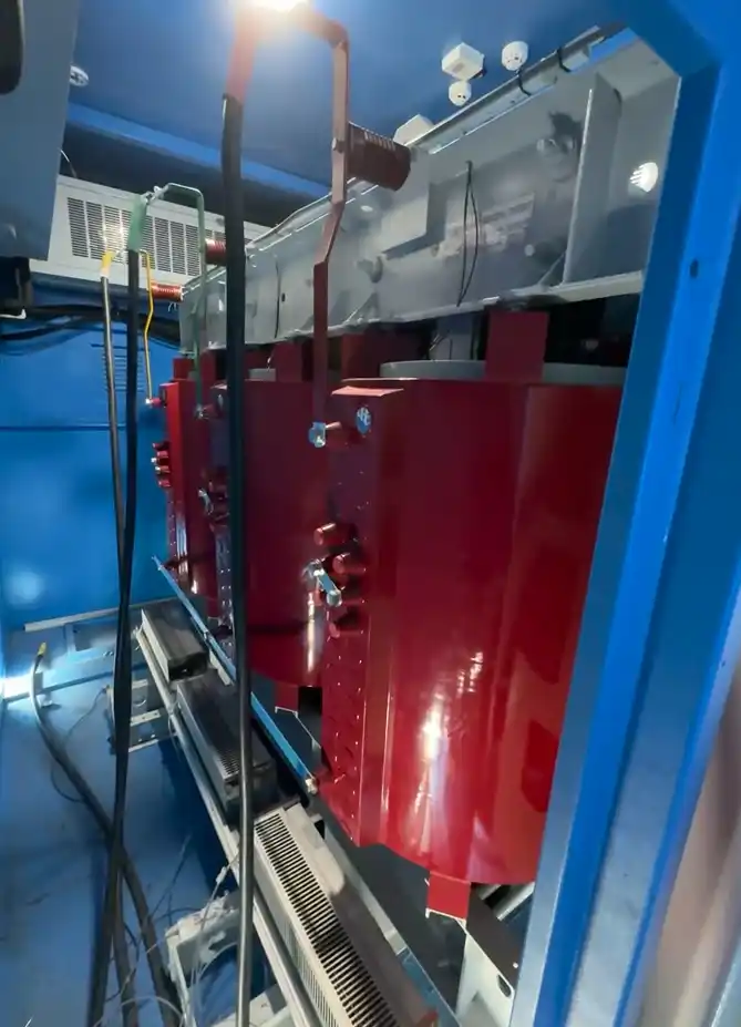
Why an Unloaded Transformer Can Draw a Large Current
Transformer core flux is related to the integral of the applied voltage.
If the breaker closes at an unfavorable point on the voltage waveform while residual flux already exists in the same direction, the transformer core can enter saturation.
Once the core saturates, magnetizing impedance falls and current rises sharply.
The current waveform may become highly asymmetrical and contain a significant DC component and harmonics before the transient decays.
This condition is different from normal transformer magnetizing current.
It is also different from motor-starting current or other vessel load transients.
A vessel transformer can therefore create a severe current transient even when the secondary breaker is open and no downstream load has yet been transferred to shore power.
Why Converter-Fed Shore Power Needs Special Attention
A strong utility grid can often supply a large short-duration transformer inrush without a major voltage disturbance.
A shore power frequency converter behaves differently.
Its semiconductor devices, control loops and protection functions operate within defined current and voltage limits. If the transformer inrush exceeds those limits, the converter may enter current limiting, distort the output voltage or trip before the transformer is successfully energized.
Repeated unsuccessful attempts can also add thermal stress and delay vessel connection.
The vessel transformer therefore has to be considered when selecting and configuring the marine frequency converter, rather than checking only the vessel’s continuous operating load.
A Project Reference: 4,625 kVA Vessel Transformer Energization
In one shore power project in which SDACME participated, the vessel-side step-down transformer was rated at 4,625 kVA with a 6.6 kV / 450 V transformation ratio.
The recorded project condition identified transformer magnetizing inrush of approximately seven times rated current during energization. Under that condition, a conventional frequency converter could trip if the transformer was energized directly without an appropriate mitigation strategy.
Project-specific operating reference. Actual transformer inrush depends on transformer construction, residual flux, switching conditions, source impedance and energization method.
This value is not a universal transformer design figure.
Actual inrush magnitude and duration depend on transformer construction, residual core flux, switching instant, source impedance, connected cable and system impedance, and the energization method.
The engineering problem is therefore not simply whether the converter has enough rated kVA.
The real question is whether the complete shore power system can energize the specific vessel transformer without exceeding converter limits or causing unnecessary protection operation.
Series-Resistance Pre-Insertion
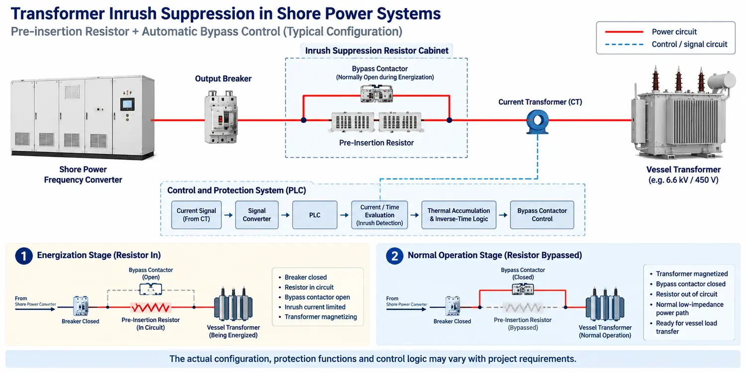
One practical mitigation method is to insert a resistor in series with the transformer during the initial energization stage.
When the breaker closes, the transformer is first energized through the resistor.
The additional resistance limits the initial current and reduces the electrical disturbance seen by the shore power converter.
After the transformer has been magnetized and the transient has reduced, a bypass contactor closes around the resistor and establishes the normal low-impedance power path.
The resistor is not intended to carry the vessel’s normal operating current continuously.
Its resistance, current capability, energy capacity and thermal duty have to match the energization event and the permitted number of repeated attempts.
If bypass occurs too late, the resistor remains exposed to current for longer than intended and unnecessary voltage drop and thermal stress can result.
If bypass occurs too early, the transformer may still present a significant transient to the converter.
In one project in which SDACME participated, a dedicated inrush-suppression resistor cabinet was installed for this function. Stainless-steel resistor elements were selected to provide increased current and thermal tolerance during the short energization duty.

Automatic Bypass Needs More Than a Fixed Timer
A fixed delay alone is not always an adequate bypass strategy.
The energization condition can change with transformer rating, connection voltage and vessel electrical arrangement.
In one shore power arrangement used in a project in which SDACME participated, the automatic bypass control had to accommodate both 6/6.6 kV high-voltage connection conditions and 400/450 V low-voltage connection conditions.
The current characteristics were different enough that the bypass decision was based on measured connection current rather than on one fixed timer alone.
A dedicated CT measured current during the connection process. The signal was then passed through a signal converter to the PLC for evaluation.
The control logic included:
- Current evaluation
- Thermal accumulation
- Inverse-time logic
- Current-and-time-based decision logic
- Bypass-contactor control
The control system has to determine whether transformer energization is developing as expected and whether the resistor can be safely removed from the circuit.
Important points to verify include:
- CT ratio and polarity
- Current measurement accuracy
- Inrush detection threshold
- Resistor insertion command
- Bypass condition
- Bypass timing
- Failure to bypass
- Unexpected current after bypass
- Thermal accumulation
- Repeated energization attempts
- Alarm and trip response
- Manual and maintenance modes
Rapid repeated energization should also be restricted if the resistor has not returned to an acceptable thermal condition.
Bypass Timing Is Part of the Engineering
The resistor itself is only one part of the inrush-control function.
Incorrect bypass timing can create another failure mode.
If the bypass contactor closes too late, the resistor may remain exposed to current for longer than intended.
If bypass occurs too early, the remaining transformer transient may still exceed the acceptable converter current.
In one project, delayed resistor switching was treated as a significant failure risk because incorrect timing could increase resistor thermal stress.
The final switching time was therefore refined through multiple field tests, together with control-logic and hardware adjustments, instead of being selected from one fixed timer value alone.
Changing only one element may move the problem rather than solve it.
Field Operation Matters, Not Only Cabinet Testing
A resistor cabinet can operate correctly in isolation and still fail to solve the complete vessel-transformer energization problem if the system sequence is wrong.
In one high-voltage shore connection to a low-voltage vessel, a resistor-based inrush-suppression arrangement was placed in service before transformer energization and removed after the energization sequence was completed.
The vessel connection was completed successfully, and the inrush-suppression arrangement operated as part of the actual shore-to-ship power sequence.
The significance of this result is not that one configuration should be copied to every project.
It shows that the mitigation method has to be verified as part of the complete converter–switchgear–transformer energization process rather than as an isolated resistor-cabinet function.
Other Transformer Inrush Mitigation Methods
Pre-insertion resistance is not the only available method.
Controlled Switching
Controlled switching can close the breaker at a selected point on the voltage waveform to reduce transformer saturation.
Its effectiveness depends on factors such as residual flux estimation, breaker pole timing, voltage measurement and control accuracy.
Controlled Voltage Buildup
Some converter topologies may allow the transformer voltage to be increased progressively rather than applied in one abrupt step.
Whether this is practical depends on the converter output stage and the connected transformer.
Auxiliary Pre-Magnetization
Some high-power systems may use an auxiliary source or other pre-magnetization method before the main source is connected.
Transformer Design
Transformer core construction, flux density and other design characteristics also affect inrush behavior.
There is therefore no single mitigation method that should automatically be applied to every shore power project.
The final choice depends on transformer characteristics, converter topology, permitted energization time, required automation and maintenance requirements.
Protection Must Distinguish Inrush from a Fault
A high current during transformer energization does not automatically mean the transformer has an internal fault.
However, the protection system cannot simply ignore high current.
Transformer differential and overcurrent protection may respond to the energization transient. Depending on the protection architecture, harmonic restraint, waveform characteristics or time coordination may be used to distinguish acceptable transformer inrush from an internal fault.
Converter protection has a similar requirement.
The converter must tolerate the approved energization transient without exposing its semiconductor devices, DC link or other power components to unacceptable stress.
The inrush-control strategy and protection settings should therefore be reviewed together with the wider shore power system architecture and components.
Transformer energization current should also be distinguished from power-flow problems such as reverse power during shore-to-ship transfer.
Test the Complete Energization Sequence
The complete energization sequence should be verified, not only the resistor cabinet.
Factory Verification
- CT signal acquisition
- PLC input scaling
- Resistor insertion command
- Bypass-contactor operation
- Interlocks
- Alarm logic
- Abnormal bypass conditions
- Simulated current and timing conditions
Where suitable transformer and test facilities are available, a representative power test provides stronger evidence than a logic-only simulation.
Site Commissioning
Site commissioning is important because the actual vessel transformer, shore converter, cable path, switchgear and control sequence are then operating together.
Useful records include:
- Transformer energization current
- Current waveform
- Voltage dip
- Converter current-limit status
- Converter alarms or trips
- Resistor insertion duration
- Bypass time
- Contactor status
- Thermal condition
- Interval between repeated attempts
In one project, repeated field tests were used to refine the final resistor switching time before the operating setting was established.
The wider factory and site verification process is covered in our shore power manufacturing and FAT guidance.
If one berth will serve several vessel types, the relevant transformer conditions should be reviewed rather than assuming that one energization profile will fit every vessel.
Common Transformer Inrush-Current Errors
- Sizing Only for Vessel Running Load
The most difficult current transient may occur before normal vessel load transfer, when the shipboard transformer is first energized. - Treating Converter Overload Capability and Transformer Inrush as the Same Requirement
Transformer inrush has a specific peak magnitude, waveform and decay characteristic that must be compared with converter current limiting and protection behavior. - Installing a Resistor Without a Verified Bypass Strategy
The resistor becomes another failure point if it remains in circuit too long, is bypassed too early or is repeatedly energized without adequate thermal recovery. - Using One Fixed Timer for Every Connection Condition
Different transformer and connection conditions can produce different current profiles. A timer value proven in one condition should not automatically be copied to another. - Copying One Vessel Setting to Another Transformer
A setting verified for one transformer should not automatically be applied to transformers with different ratings, voltage ratios, core designs or energization conditions.
Information Needed for an Inrush Review
A preliminary engineering review does not require every transformer parameter to be available on the first day.
Minimum Information to Start
- Transformer rated power
- Primary voltage
- Secondary voltage
- Transformer nameplate or datasheet
- Shore converter capacity
- Converter output voltage
- Proposed energization sequence
- Single-line diagram, if available
For a Detailed Engineering Review
- Transformer impedance
- No-load current
- Manufacturer inrush data
- Transformer core information, where available
- Converter short-duration current capability
- Converter current-limit behavior
- Converter trip behavior
- Shore and vessel breaker arrangement
- Existing transfer or synchronizing equipment
- Permitted voltage dip
- Permitted connection time
- Expected number of energization attempts
- Protection and classification requirements
The objective is to review the transformer, converter, mitigation hardware, control timing and protection as one energization system.
Frequently Asked Questions
Can transformer inrush occur with no secondary load?
Yes. Transformer inrush is caused by transient core magnetization and can occur while the transformer secondary is open and no vessel load is connected.
Is transformer inrush always six to eight times rated current?
No. Values in this range can occur under specific transformer and switching conditions, but they are not universal design values. Actual magnitude and duration depend on transformer construction, residual flux, switching instant, system impedance and source characteristics.
Can the shore power frequency converter simply current-limit the inrush?
It may enter current limiting, but that does not guarantee successful transformer energization. If the converter reduces the output voltage too strongly or reaches a protection threshold, the transformer may fail to establish normal magnetization and the converter may trip.
Why is the pre-insertion resistor bypassed?
The resistor is needed only during the initial transformer energization. Leaving it in the normal power path would introduce unnecessary voltage drop, power loss and heating.
Why not use one fixed bypass timer?
A timer only measures elapsed time. It does not directly confirm the electrical condition of the transformer or the current flowing through the energization path. Current-based logic, combined with time and thermal conditions, provides a stronger basis for the bypass decision.
Can one inrush setting serve every vessel?
Only when the relevant transformer and connection conditions fall within an already reviewed operating range. Different transformer ratings, voltage ratios, connection methods and energization conditions may require different settings or control profiles.
Discuss Your Vessel Transformer Energization Requirement
Send us the vessel transformer data, shore power converter configuration and proposed switching sequence.
If the full transformer data is not yet available, start with the transformer nameplate, single-line diagram or the electrical information you already have.
We can review the expected energization condition, current-limiting method, resistor and bypass logic, protection coordination and commissioning measurements required for the project.
Send Your Transformer Data