
What Causes Reverse Power During Shore-to-Ship Transfer?
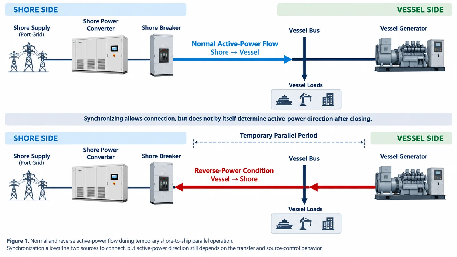
Reverse power occurs when active energy flows from the vessel back toward the shore power system instead of from shore to vessel.
The highest risk is during a no-break transfer, when the shore source and a shipboard generator are temporarily connected in parallel. A transfer can pass the synchronization check and still develop reverse power afterward if generator unloading, shore converter control or active-power sharing does not develop as intended.
The solution is not simply to add a reverse-power relay.
Synchronization, generator control, converter response, power-direction measurement and breaker protection have to operate as one coordinated transfer system.
Why Temporary Parallel Operation Creates Reverse-Power Risk
When two AC sources are connected in parallel, their electrical conditions have to remain closely coordinated.
Frequency difference causes the phase angle to move. Voltage difference mainly affects reactive current. Active-power flow is influenced by phase-angle relationship and by how the two sources share the load.
During transfer from ship generation to shore power, the vessel generator should unload while the shore source takes over the vessel load.
If this load transfer is not coordinated correctly, the generator can temporarily push active power back toward the shore system.
The same issue can occur in the opposite direction when the vessel returns from shore power to its own generator. The generator is synchronized and loaded before the shore source is removed, so there is again a temporary period in which both sources are connected.
The longer that parallel condition lasts, the more important the generator-control and converter-control response becomes.
In one shore power arrangement used in a project in which SDACME participated, the operating strategy also reduced the number of ship generators involved during connection and disconnection where the vessel operating procedure allowed it. The same arrangement required improved detection accuracy and reverse-power protection on both the shore and vessel sides.
Break-before-make transfer removes the temporary source-paralleling condition, but it introduces a power interruption.
The transfer method therefore has to be selected from the vessel load requirement and the actual shore-to-ship electrical arrangement, not simply from a preference for seamless transfer.
For the overall connection sequence, see our shore power connection procedure.
Synchronization Accuracy Is Only the Starting Point
A synchronizer checks whether shore and vessel sources are close enough in:
- Voltage
- Frequency
- Phase sequence
- Phase angle
Passing this window means the sources are suitable for connection at that instant.
It does not guarantee correct active-power sharing after the breaker closes.
After paralleling, power flow is also affected by:
- Vessel generator governor behavior
- Generator load-sharing control
- Shore converter frequency control
- Voltage control
- Generator unloading rate
- Communication delay
- Measurement accuracy
- Permitted parallel time
The engineering review therefore has to cover both synchronization before closing and power control after closing.
How Reverse Power Is Detected
Reverse power is a power-direction problem.
The controller has to determine whether active energy is moving from shore to vessel or from vessel back toward the shore system.
In one converter-based shore power arrangement used in a project in which SDACME participated, reverse-power detection used both AC-side electrical measurements and converter-side DC behavior.
On the AC side, the system measured output voltage and current and calculated the direction of active power.
The current was resolved into active and reactive components. A positive active component represented normal shore-to-vessel power flow. A negative active component indicated that energy was returning from the vessel toward the shore source.
This gives the control system a direct indication of power direction rather than relying only on breaker status or generator commands.
Measurement polarity is therefore critical.
Incorrect CT polarity, incorrect phase association or inconsistent voltage references can make normal forward power appear as reverse power.
These measurement conditions should be verified before reverse-power thresholds are adjusted.
Why the Converter DC Link Provides a Second Indication
AC-side power calculation is one part of the protection strategy.
The converter DC link can provide another indication of reverse-energy stress.
If energy flows back into a converter and that energy cannot be transferred to the upstream grid fast enough, the DC-link voltage can rise.
In the project arrangement above, reverse-power supervision therefore did not depend on only one electrical indication.
The system considered both:
- AC-side active-power direction
- DC-link behavior
The AC measurement identifies the direction of power flow.
The DC link shows how the converter itself is responding to the returned energy.
Control Should Act Before Protection Has to Trip
Reverse-power control and reverse-power protection have different jobs.
Control attempts to recover the transfer.
Protection removes the unsafe condition when recovery is no longer successful.
In the project control logic, a negative active or torque-current condition, or an abnormal increase in DC-link voltage, initiated corrective converter action.
The converter progressively adjusted its operating point to move active power back toward the normal shore-to-vessel direction.
If the condition continued and the DC-link voltage reached the protection limit, the output breaker was opened.
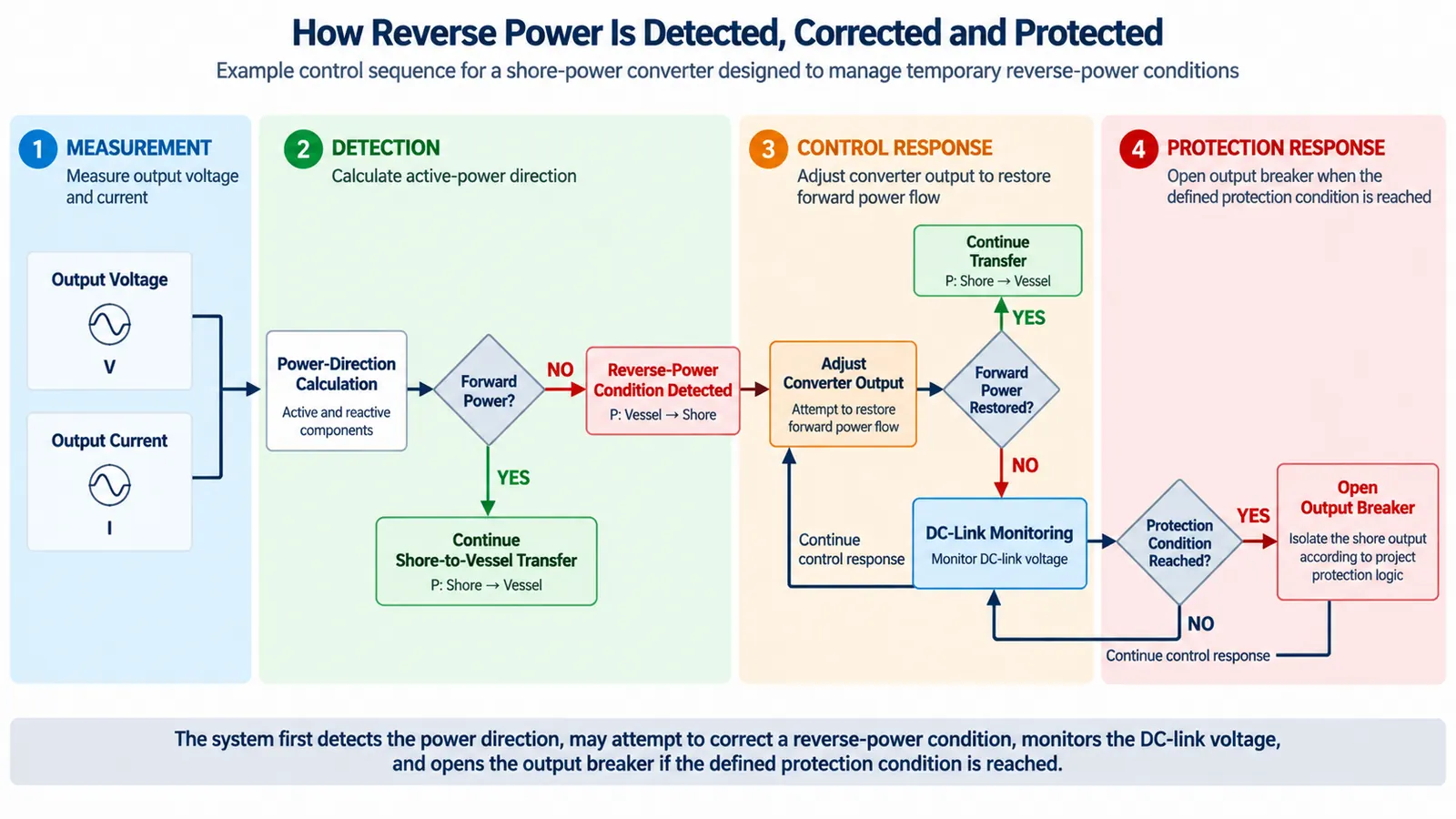
This sequence is more useful than treating every short reverse-power condition as an immediate trip.
It is also safer than allowing reverse energy to continue indefinitely while relying only on converter control.
The actual control threshold, delay and trip boundary have to match the converter topology and the approved transfer sequence.
Why Converter Topology Matters
Not every shore power converter handles reverse energy in the same way.
Some converter architectures can return energy toward the upstream network under defined conditions.
Others cannot be assumed to operate regeneratively.
If returned vessel energy has no approved path through the converter, the DC link can become a critical energy-storage boundary.
The engineering team should confirm:
- How reverse power is detected
- Whether reverse energy can be regenerated
- Whether it can only be tolerated for a limited period
- How converter control responds
- What condition initiates protective trip
- Which breaker opens
- What happens if corrective control fails
These questions should be resolved before temporary parallel operation is approved.
The topology and energy-handling limits of the marine frequency converter should therefore be confirmed during the transfer review.
A Real Load-Transfer Reference
A real shore-to-ship transfer shows why reverse-power protection has to be considered together with the complete load-transfer sequence.
In one container-terminal shore power project in which SDACME participated, the ship generators were carrying approximately 1.5 MW when the shore transfer began.
The control system transferred the vessel load to shore power over approximately 30 seconds, after which the ship generator was disconnected.
Project-specific operating reference. These figures are not universal transfer targets or protection settings.
Two shore-connection tests were completed in that project. Vessel water-pump starting tests were also carried out while shore power was supplying the ship.
These figures are project-specific, not universal transfer targets.
Their engineering value is different: they show that a no-break transfer is a controlled operating process with measurable load movement and a defined period of source interaction. It is not only a synchronizer closing a breaker.
The important questions are:
- How quickly the generator unloads
- How the shore converter accepts the load
- How long the two sources remain paralleled
- Whether active power remains in the intended direction
- What happens if the transfer stops developing correctly
Breaker Coordination on the Shore and Vessel Sides
Reverse power is not only a converter event.
The shore breaker, vessel breaker, synchronizer, converter controller and ship generator controls all participate in the transfer.
The cause-and-effect logic should define the required response to conditions such as:
- Reverse power
- Synchronization failure
- Converter protection
- Communication loss
- Vessel-side trip
- Emergency stop
The design should also define which breaker is expected to open and whether an automatic retry is permitted.
Uncoordinated breaker action can make event diagnosis and recovery more difficult.
Time-synchronized event records are useful because shore and vessel logs can then be compared to determine whether the event started with generator unloading, synchronization, converter response, communication or a switching command.
The relationship between switchgear, protection and control is covered in more detail in our shore power system architecture and components page.
Reverse Power Is Not Reverse Phase Sequence
These two conditions should not be confused.
Reverse power describes the direction of active energy flow.
Reverse phase sequence describes the order of the three AC phases.
A vessel can have the correct phase sequence and still produce reverse power during temporary source paralleling.
The two problems therefore require different detection and protection logic.
The Connection Procedure Affects Reverse-Power Risk
Reverse-power protection starts before the two sources are paralleled.
In a shore-connection procedure used in a project in which SDACME participated, the shore supply was first brought to the vessel-side main-switchboard connection point.
Before paralleling, the vessel operator checked:
- Phase sequence
- Voltage
- Frequency
Where adjustment was required, the shore converter settings were corrected before the paralleling operation continued.
Only after the electrical conditions were confirmed did the vessel proceed with the shore-power parallel transfer.
The ship generator was then disconnected after the load had been transferred to shore.
Correct pre-connection checks reduce the number of variables the control system has to manage after the sources are paralleled.
See the full shore power connection procedure for the wider vessel-connection sequence.
What Should Be Verified Before a No-Break Transfer
A no-break transfer should not be approved from a general functional description alone.
The actual shore and vessel interfaces have to be checked.
The review should confirm:
- Shore and vessel single-line diagrams
- Converter topology
- Converter reverse-energy capability
- Vessel generator ratings
- Generator governor behavior
- Load-sharing arrangement
- Synchronizer configuration
- Permitted synchronization window
- CT and VT locations
- CT and VT ratios
- CT polarity
- Generator unloading method
- Shore load-pickup method
- Maximum permitted parallel time
- Reverse-power control logic
- Shore and vessel protection settings
- Breaker trip matrix
- Emergency-stop logic
- Communication interface
- Event-recording requirements
Until these conditions are confirmed, break-before-make transfer should be treated as the conservative operating option where a short interruption is acceptable.
How to Verify Reverse-Power Detection and Protection
Reverse-power commissioning should separate three different questions:
- Is power direction measured correctly?
- Does the control system respond correctly?
- Does protection operate correctly when control cannot recover the condition?
Verify Measurement Direction
- CT polarity
- VT phase assignment
- Active-power calculation
- Forward-power indication
- Reverse-power indication
- DC-link voltage measurement
- Signal scaling
A normal shore-to-vessel power condition should never appear as reverse power because of wiring or reference errors.
Verify Converter Control Response
Test how the converter responds when power direction approaches the approved reverse-power boundary.
The test should confirm that corrective action moves the operating point back toward positive shore-to-vessel power without unstable oscillation or unnecessary trip.
Verify Protective Trip
- Reverse-power threshold
- Time delay
- Signal filtering
- DC-link protection level
- Output-breaker command
- Alarm indication
- Event recording
A failed corrective action should result in the intended protective response.
Verify the Actual Transfer
During an approved site transfer, useful records include:
- Shore voltage
- Vessel voltage
- Frequency
- Phase angle
- Active power
- Reactive power
- Converter current
- DC-link voltage
- Vessel generator load
- Shore breaker status
- Vessel breaker status
- Event timestamps
Abort conditions should be defined before the test starts.
The broader factory and commissioning process is covered in our shore power manufacturing and FAT page.
Common Reverse-Power Problems
- Incorrect CT Polarity
Incorrect CT polarity can reverse the calculated active-power direction and cause the wrong control or protection response. - Protection Set Too Sensitive
A threshold that is too sensitive can create nuisance trips during short measurement disturbances or harmless transient conditions. - Protection Set Too Slow
A delay that is too long can allow excessive reverse energy to enter the converter before protection operates. - Parallel Operation Lasts Too Long
A longer parallel period increases exposure to load-sharing and generator-control errors. - Generator and Converter Controls Are Reviewed Separately
During a no-break transfer, the shore source and ship generator form one temporary parallel electrical system and have to be reviewed together. - The Transfer Is Approved Without Enough Vessel Data
Generator controls, synchronizer settings, breaker logic and converter topology all affect the result.
Information Needed for a Reverse-Power Review
A preliminary review can begin before every control parameter is available.
Minimum Information to Start
- Shore single-line diagram
- Vessel single-line diagram
- Vessel generator ratings
- Shore converter model or topology
- Synchronizer information
- Proposed transfer sequence
- Existing reverse-power settings
For a Detailed No-Break Transfer Review
- Generator governor and load-sharing information
- CT and VT ratios and polarity
- Permitted synchronization window
- Maximum parallel time
- Required generator unloading rate
- Shore load-pickup sequence
- Breaker interlock and trip logic
- Emergency-stop matrix
- Converter reverse-energy capability
- Event-recording requirements
- Vessel or classification approval requirements
Before first connection, the shore and vessel teams should also agree on the transfer method, operating responsibilities, communication method, abnormal-condition response and emergency disconnection procedure.
The objective is to review synchronization, temporary paralleling, power-direction detection, converter response and breaker protection as one complete transfer function.
Frequently Asked Questions
Can reverse power occur without an electrical fault?
Yes. It can occur during normal temporary source paralleling when synchronization, generator unloading or active-power sharing does not develop as intended.
Is reverse power the same as reverse phase sequence?
No. Reverse power concerns active-energy direction. Reverse phase sequence concerns phase order. They require different detection methods.
Does every shore power converter accept regenerative power?
No. The answer depends on converter topology and the permitted path for returned energy. Reverse-energy capability has to be confirmed before temporary parallel operation is approved.
Can a reverse-power relay alone solve the problem?
No. A relay can detect a condition and initiate protection, but successful transfer also depends on synchronization, generator control, converter control, power-direction measurement and breaker sequence.
Why monitor DC-link voltage?
Returned energy can increase DC-link voltage when the converter cannot transfer that energy elsewhere fast enough. DC-link behavior can therefore provide an additional indication alongside AC-side power-direction measurement.
Does a successful synchronization check guarantee correct power flow?
No. Synchronization confirms the conditions at breaker closing. Power direction after closing still depends on generator unloading, converter control and the transfer sequence.
Is no-break transfer required for every vessel?
No. Break-before-make transfer is appropriate for some vessels and operating conditions. The correct method depends on the vessel load requirement, onboard equipment and approved operating sequence.
Discuss Your Shore-to-Ship Transfer Requirement
Send us the shore and vessel single-line diagrams, generator information, synchronizing arrangement and proposed transfer sequence.
If the full control data is not yet available, start with the SLD, generator ratings and existing switching procedure.
We can review the power-direction measurement, converter response, reverse-power protection, breaker coordination and commissioning data required for the transfer.
Send Your Transfer Data