
Modular IGBT Power Units and Redundancy in Shore Power Converters
A modular shore power converter is not automatically redundant.
Redundancy should be defined by what the complete converter can still deliver after a specified power-cell fault. Can the affected cell be isolated or bypassed? Can acceptable three-phase output be restored? Do the remaining cells have enough voltage capability for the required operating point? Can the vessel load still be supplied at full capacity, only at a defined derated level, or not at all?
Those questions matter more than the words modular, cell bypass, or N+1 on a specification sheet.
Why One Power-Cell Fault Changes the Converter Operating Condition
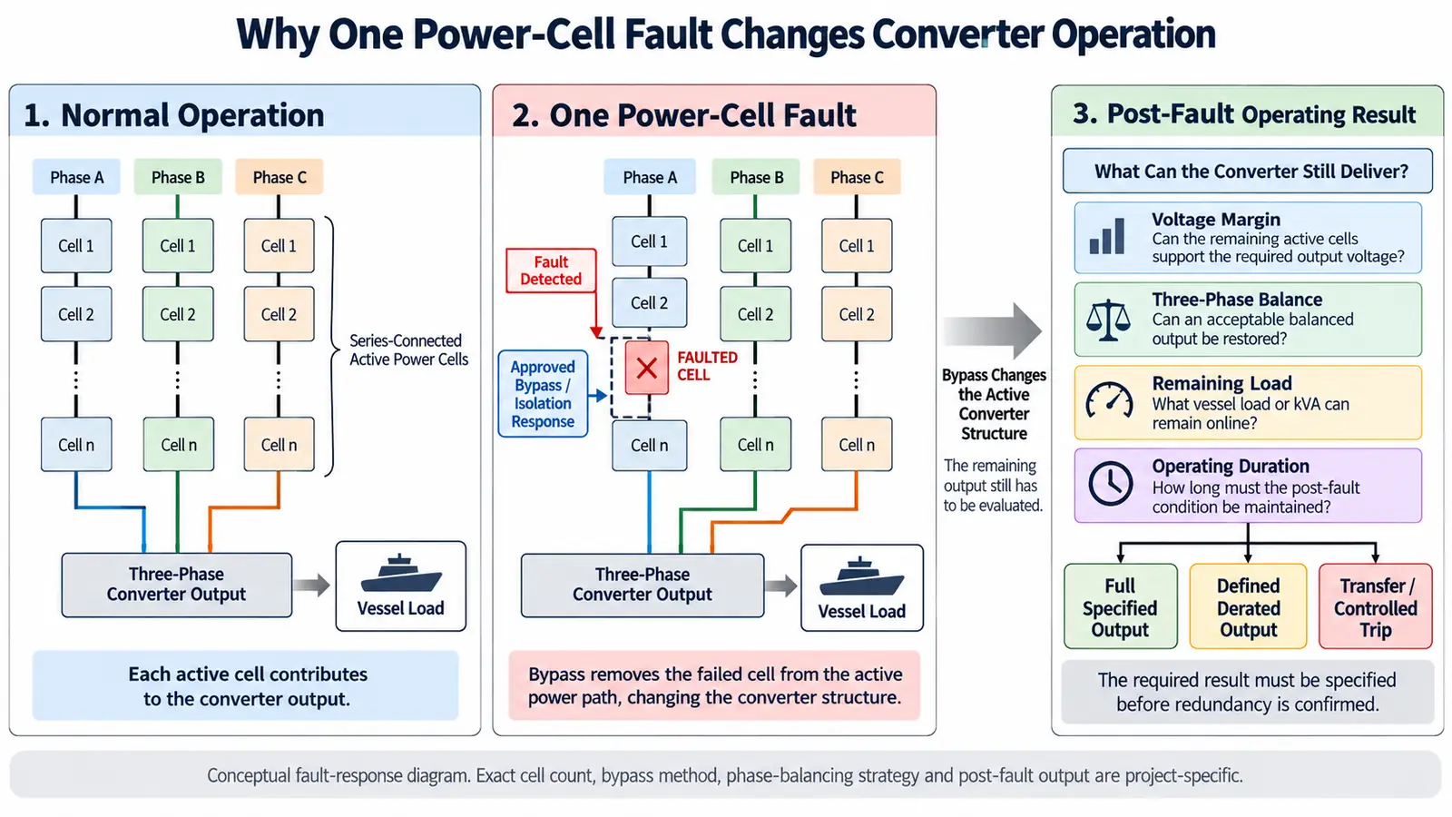
In a cascaded converter, several active power cells work together to build the output voltage.
In one six-cell-per-phase shore power converter configuration, six power cells were connected in series in each phase. Each cell contributed to the phase voltage, and the combined cell outputs produced the required line voltage.
A failed cell is therefore not simply an isolated replaceable component. It is part of the active voltage-producing chain.
When one cell has to be removed from that chain, the converter may face several simultaneous changes:
- less available voltage from the affected phase;
- a different active-cell structure between phases;
- reduced post-fault output capability.
A successful bypass removes the faulty unit from the active power path, but the converter still has to establish an acceptable output afterward.
What Is Inside a Modular Converter Power Cell?
In this type of cascaded converter, each power cell is a power-conversion subassembly rather than a single switching device.
In one shore power converter design, each unit included an IGBT rectifier stage, DC-link capacitor, IGBT inverter bridge, drive circuits, protection, signal acquisition and fiber-optic communication. The units in that configuration were designed with the same structural and electrical characteristics so they could be interchanged.
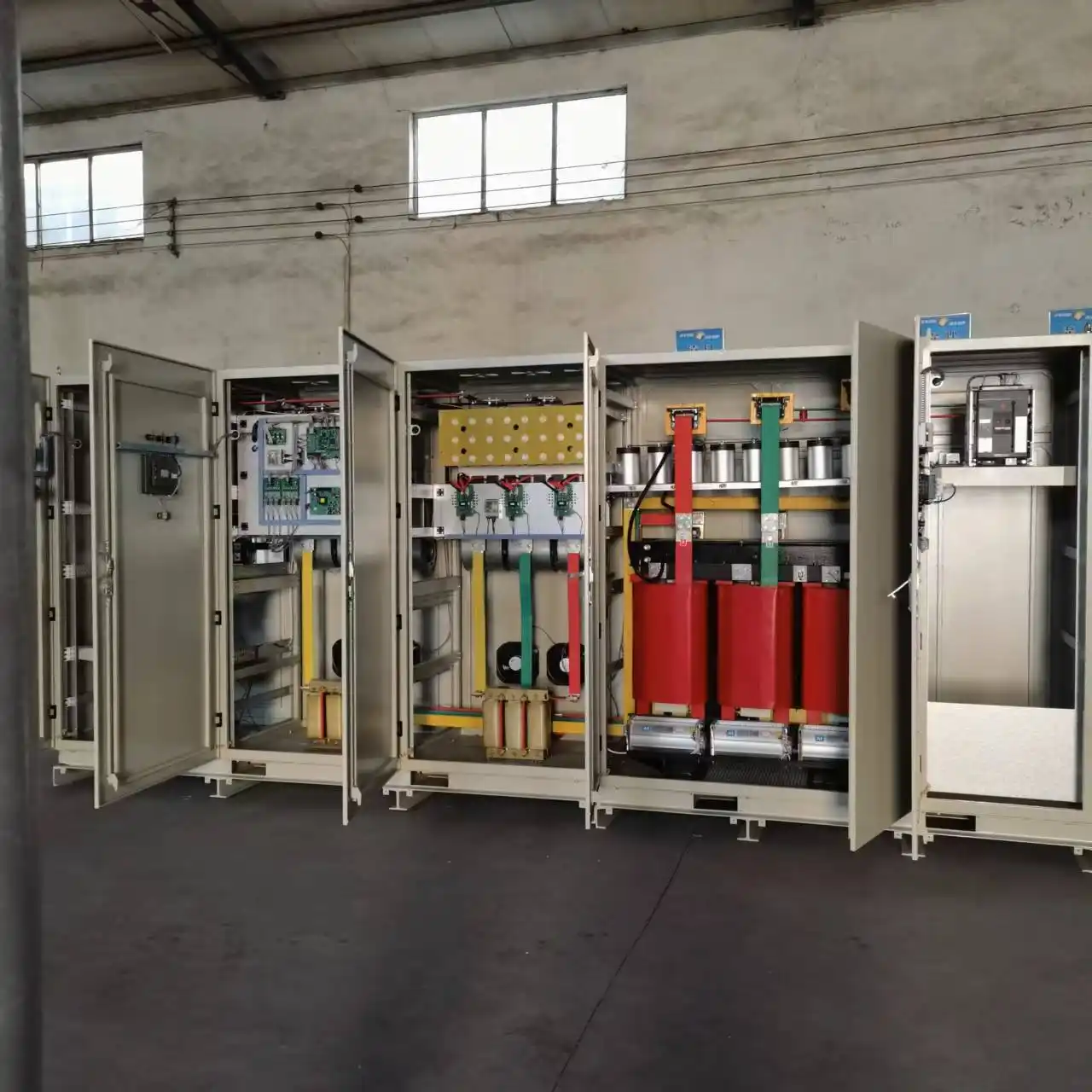
This modular structure improves serviceability. A fault can be localized to a smaller functional unit, and a compatible cell can be replaced without rebuilding the complete converter power section.
But serviceability and redundancy are different requirements.
A converter can therefore be highly modular and still trip after one cell failure if the required bypass path, electrical margin and post-fault control strategy have not been engineered into the system.
What Happens When One Power Cell Fails?
In one 630 kVA shore power configuration, the controller was specified to detect a fault in an individual power module and issue a warning. For a severe module fault, the design called for bypassing or removing the affected power unit while maintaining balanced three-phase voltage and continued converter operation.
That is already a meaningful redundancy requirement.
It does not, however, define the complete post-fault result.
Continued operation alone does not establish that:
- the original rated kVA remains available;
- the original output-voltage margin is unchanged;
- every cell fault can be bypassed;
- the converter can remain indefinitely in the degraded condition.
Those results have to be specified separately.
Why Bypass Alone Does Not Define Redundancy
A bypass function removes a failed cell from the active power path.
The Remaining Cells Still Need Enough Voltage Capability
Because the active cells contribute directly to converter output voltage, removing one cell changes the available voltage-producing structure.
In some engineered cascaded-converter designs, the control system checks whether the remaining healthy cells can still support the required output after a cell is bypassed. Other modular converter designs use additional cells above the minimum normal operating requirement to create electrical redundancy margin.
For a shore power project, this margin has to be evaluated at the required operating voltage and load.
Counting cells alone is not enough.
The Three Phases Still Need an Acceptable Output Structure
A cell fault also affects phase balance.
If one cell is removed from only one phase, the affected phase no longer has the same active-cell structure as the other two. Depending on the topology and control method, the converter may need additional post-fault action to restore acceptable line-to-line voltages.
The 630 kVA shore power configuration described above explicitly required balanced three-phase voltage after the affected power unit was bypassed or removed.
A successful bypass is therefore not a complete acceptance result. The converter output after the bypass still has to be evaluated.
Different Redundancy Strategies Produce Different Post-Fault Results
There is more than one way to manage the loss of a power cell.
Different strategies trade available output, hardware margin and control complexity against one another.
| Strategy | What it does | Main advantage | Main trade-off |
|---|---|---|---|
| Symmetrical bypass | Removes corresponding cells so the phases return to a similar active-cell structure | Straightforward way to restore phase symmetry | Healthy voltage-producing cells may also be removed from service |
| Control-based balancing | Uses modified post-fault control or modulation to retain more healthy cells | Preserves more available converter capability | Higher control and verification complexity |
| Extra redundant cells | Installs electrical margin above the minimum normal requirement | Can support stronger post-fault output targets | More cells, components, space, cooling demand and spares |
In one medium-voltage converter implementation, a fault in one phase is handled by bypassing corresponding cells in the other phases so that each phase retains the same active-cell count. The converter can then continue operating at reduced capacity.
Other cascaded-converter strategies use modified post-fault control to retain more healthy-cell capability.
Define Redundancy by the Required Post-Fault Output
The word redundancy can describe very different operating results.
These requirements should not be mixed together.
Continued Operation
The converter remains in operation after the specified power-cell fault instead of immediately shutting down.
This does not by itself define how much load remains available.
Defined Derated Operation
The converter continues operating, but at a lower specified voltage, power or load.
In one medium-voltage converter implementation, automatic cell bypass allows operation to resume at reduced capacity after the faulty cell is removed from service.
That is still a valid redundancy strategy when the connected load can accept the reduced operating point.
Full-Rated Post-Fault Operation
Some projects cannot accept a reduction in available power after one approved cell fault.
That is a significantly stronger requirement.
It requires enough installed electrical margin and an appropriate control strategy to maintain the specified output after the fault.
One OEM implementation uses an N+1 cell-redundancy option to maintain rated-power operation after one cell is bypassed, with the available capability still dependent on the applicable output-voltage range.
The phrase N+1 power cells is therefore incomplete by itself.
N+1 for What Operating Result?
- continued operation only?
- a defined derated load?
- full rated kVA?
- full output at which operating voltage?
- operation for a limited transfer period?
- continuous operation until the next maintenance window?
A useful redundancy specification defines both the tolerated failure and the required operating result afterward.
The Bypass Path Is Part of the Redundancy Architecture
The bypass mechanism itself can also become a failure dependency.
If the bypass path relies on the same communication, control-power or control resources affected by the cell fault, the fault may compromise both the power cell and the function intended to bypass it.
Some converter designs address this by separating bypass control or auxiliary-supply functions more clearly from the individual power cell.
For a shore power RFQ, “automatic bypass required” may therefore be too vague.
The project may also need to define:
- which fault conditions permit bypass;
- which faults require a converter trip;
- how the bypass function is controlled;
- how successful bypass is confirmed;
- what happens if the bypass command itself fails.
Power-Cell Redundancy Is Not Complete Converter Availability
Power-cell redundancy addresses selected cell-level failures.
It does not remove every shared failure that can stop the complete converter.
Cooling provides a clear project example.
In one converter cooling configuration, a cooling-system fault generated an alarm while the converter initially remained in operation. If the condition was not corrected and temperature reached the configured upper limit, the converter was required to stop.
A converter can therefore tolerate a selected power-cell failure and still be vulnerable to a shared cooling failure.
For projects with demanding availability requirements, the scope of redundancy should be stated explicitly. Cell-level fault tolerance should not be treated as a substitute for complete converter or shore power system availability.
The thermal side of this issue is covered separately in the shore power system cooling and HVAC design .
Electrical Bypass Does Not Mean Energized Physical Removal
Electrical bypass and physical replacement are different functions.
A converter may remove a faulty cell electrically from the active power path while the remaining system continues operating.
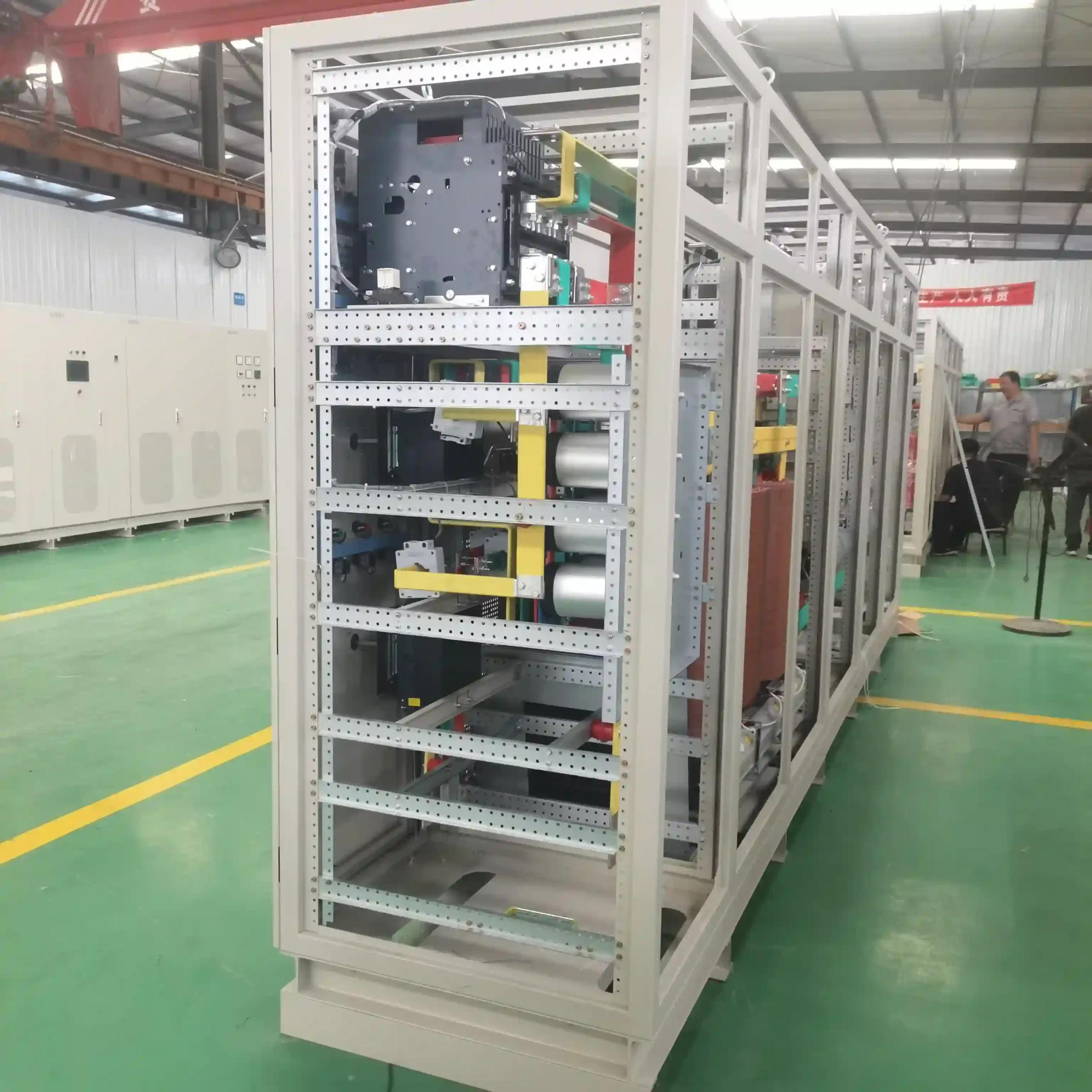
Physical replacement should follow the equipment's approved maintenance and isolation procedure.
Modular construction can make replacement easier, but it should not be interpreted as automatic hot-swap capability.
How Should Power-Cell Redundancy Be Verified?
Normal converter FAT does not automatically prove post-fault redundancy.
In one shore power test programme, converter verification included multiple load levels, overload conditions, three-phase unbalance, output voltage, current, frequency and protection checks.
These tests establish important converter performance under defined operating conditions. If continued operation after a power-cell fault is a contractual requirement, the post-fault condition needs its own acceptance logic.
Establish the Normal Baseline
Before the simulated fault, record the agreed normal operating condition:
- output voltage;
- frequency;
- load or kVA;
- phase balance;
- active-cell status.
This establishes the reference condition for the test.
Apply an Approved Fault Simulation
The simulated condition should be agreed before the witness test.
Define:
- the affected phase;
- the affected cell;
- the permitted fault-simulation method;
- the operating voltage;
- the test load.
A cell fault should not be improvised during FAT.
Verify Detection and Fault Localization
Confirm that the controller identifies the affected unit and provides the required alarm and status information.
In one shore power monitoring configuration, core power-component diagnostics identified fault type and fault location and provided local and remote alarm information.
Verify the Approved Bypass or Isolation Response
Confirm that the affected cell is handled according to the converter design.
The exact sequence may differ between architectures. The acceptance procedure should verify the specified result rather than assume every converter uses the same fault-response logic.
Measure the Post-Fault Three-Phase Output
After the fault response, check the actual converter output.
Relevant measurements can include:
- line-to-line voltage;
- output frequency;
- voltage balance;
- stable operating condition.
This step determines whether the converter has recovered to an acceptable electrical state.
Apply the Contractual Post-Fault Load
This is the decisive test.
The converter should supply the load that the project specification requires after the defined fault.
That may be:
- full rated load;
- a specified derated load;
- a temporary transfer load.
Verify Recovery
Finally, confirm the required recovery state.
Depending on the project, this may include:
- fault reset;
- controlled restart;
- maintenance status;
- return to normal operation after repair or cell replacement.
The wider inspection and acceptance programme can be coordinated with the shore power manufacturing and FAT process.
What Should an RFQ Specify for Converter Redundancy?
A useful redundancy specification begins with the normal operating requirement and then defines the fault condition and required post-fault result.
Normal Operating Data
Provide:
- converter input voltage;
- required output voltage;
- output frequency;
- rated kVA;
- overload duty;
- required operating modes.
Power-Cell Architecture
Confirm:
- converter topology;
- cells per phase;
- normal active-cell arrangement;
- available electrical margin, where relevant.
Fault-Tolerance Requirement
Define:
- the fault that must be tolerated;
- the number of unavailable cells to be tolerated;
- automatic or manual bypass;
- required three-phase result after the fault.
Required Post-Fault Output
State:
- required remaining voltage;
- required remaining kVA or vessel load;
- permitted derating;
- required operating duration;
- whether transfer back to the vessel generator is acceptable.
Acceptance Requirement
Define:
- permitted fault-simulation method;
- measurement points;
- voltage-balance requirement;
- remaining-load requirement;
- alarm and status requirements;
- FAT or witness-test requirement.
Replacement-Cell Compatibility
Replacement-cell compatibility should be confirmed against the approved converter configuration and supplier requirements.
Detailed spare quantities and long-term maintenance planning should be handled separately from the redundancy definition itself.
Frequently Asked Questions
Does a modular shore power converter keep running after any power cell fails?
No.
Continued operation depends on the fault type, bypass architecture, remaining electrical margin and post-fault control strategy. A modular structure alone does not guarantee continued operation.
Does power-cell bypass mean the converter still has full rated capacity?
No.
Some converter architectures continue at reduced capacity after a cell is bypassed. Full-rated post-fault operation requires sufficient installed electrical margin and a control strategy designed for that result.
Why would healthy cells in other phases also be bypassed?
In some fault-tolerant architectures, corresponding healthy cells are bypassed to restore a symmetrical active-cell structure.
Other converter designs use different post-fault balancing methods. The appropriate strategy depends on the topology and the required remaining output.
Is “N+1 power cells” enough to specify redundancy?
No.
The specification should also define the fault to be tolerated, the voltage and load that must remain available, the permitted operating duration and how the result will be verified.
Can a bypassed power cell be removed while the converter remains energized?
Electrical bypass alone does not establish energized physical-removal capability.
Physical replacement is governed by the approved equipment maintenance and isolation procedure.
Technical References
- IEC/IEEE 80005-1:2019, including AMD1:2022 and AMD2:2023 — High-voltage shore connection systems; system scope includes frequency conversion, control, monitoring and related shore-connection functions.
- IEC/IEEE 80005-3:2025 — Low-voltage shore connection systems; includes applicable semiconductor frequency converters together with protection, control, monitoring and interlocking functions.
- Siemens SINAMICS PERFECT HARMONY GH180 Technical Documentation — Cascaded power-cell topology, cell bypass, redundancy options and post-fault voltage-capability considerations.
- Rockwell Automation PowerFlex 6000T Programming Manual — Cell-bypass implementation, phase-balancing examples and reduced-capacity post-fault operation.
- ABB technical material on modular power conversion — Relationship between cell count, output-voltage capability, redundancy margin and converter-design trade-offs.
- IET Power Electronics research on fault-tolerant cascaded H-bridge converters — Post-fault voltage imbalance, cell-bypass strategies and control-based recovery of balanced converter output.
Define the Required Post-Fault Result Before Selecting the Converter
A redundancy review should start with the operating result the vessel actually needs after the specified fault.
Send the required input and output voltage, frequency, rated load, overload duty, converter architecture if already defined, required post-fault voltage and load, permitted derating, operating duration, and FAT requirements.
With those inputs, the converter redundancy requirement can be reviewed as an engineering condition rather than a label such as modular, cell bypass, or N+1.
Send Your Project Requirements