
Ship-to-Shore Equipotential Bonding and Grounding Explained
Before a shore power breaker is allowed to energize the vessel, the protective connection between shore and ship has to be established and proven.
A plug that appears to be fully inserted is not enough. The bonding path includes the protective conductor, connector contacts, cable equipment and vessel-side connection points. The pilot circuit then provides part of the permissive logic used to decide whether the electrical connection is ready for operation.
If that protective path is missing, excessively resistive or not proven by the required safety circuit, the shore power system should not proceed as though the connection were normal.
Equipotential Bonding Is Not the Same as Neutral Grounding
Several grounding-related functions exist in a shore power system, but they should not be treated as one design item.
Equipotential bonding provides the protective connection between shore and vessel during the shore-power interface. The shore installation also has its own earthing arrangement, while the transformer neutral arrangement and earth-fault protection belong to the wider electrical design.
These functions interact, but one does not replace another.
For this reason, a vessel single-line diagram is more useful than a voltage value alone. The transformer arrangement, protective conductor, shore connection and vessel-side distribution all need to be understood before the final protection philosophy is confirmed.
For the wider electrical path, see our shore power system architecture and components page.
The Protective Conductor Must Be Established Before Power Is Applied
In one high-voltage shore-connection arrangement, the connector includes the three phase conductors, an E protective-earth contact and pilot contacts including P3.
The physical contact arrangement is designed so that the E connection is established before the main phase connection is completed. The pilot circuit then forms part of the logic used to confirm that the connection is ready for operation.
The important point is not the contact name by itself. It is the sequence.
The vessel should not have to wait until the main conductors are energized before a protective bonding path exists.
In this high-voltage connection arrangement, the E contact provides the equipotential connection, while P3 monitors the bonding-related safety circuit. The exact pilot designation and contact arrangement still depend on the selected shore-connection equipment and project requirements.

What the Pilot Circuit Proves — and What It Does Not
A pilot circuit can confirm part of the connection condition. It cannot make a poor physical connection acceptable.
In the arrangement described above, P3 monitors the equipotential circuit and provides a signal used by the safety logic. If that circuit is not proven, the operating sequence is blocked.
But pilot monitoring has limits.
A connector may still suffer from corrosion, worn contacts, poor mechanical engagement or excessive resistance. The vessel-side cable reel and slip rings introduce additional connection points that can also deteriorate in service.
Pilot monitoring is therefore one layer of protection. It does not replace a sound physical connection.
A dependable connection needs three things working together:
- sound shore-to-ship connection hardware,
- a functioning pilot and interlock circuit,
- inspection and electrical verification of the actual connection.
Equipotential monitoring alone may not identify every connection problem. Reliable connector engagement, maintenance and pilot interlocking still matter.
Why an Equipotential Connection Can Fail
The bonding path can fail even when the connector looks normal from the outside.
One problem is excessive resistance in the protective path. An undersized protective conductor can increase impedance. Poor contact between mating parts can do the same.
The connector itself is another critical point. Insufficient contact area, contamination, oxidation and aging can all increase contact resistance.
The vessel side also matters. Cable-reel slip rings, cable terminations, plugs and sockets are part of the same electrical path. A defect on the ship cannot be corrected by changing a shore-side relay setting.
Is the protective conductor large enough?
More importantly: is the complete protective path electrically sound from the shore equipment through the connection system to the vessel?
A large conductor alone does not prove that.
How the Interlock Should Respond to an Unproven Bonding Condition
An unproven protective connection should block energization according to the approved control philosophy.
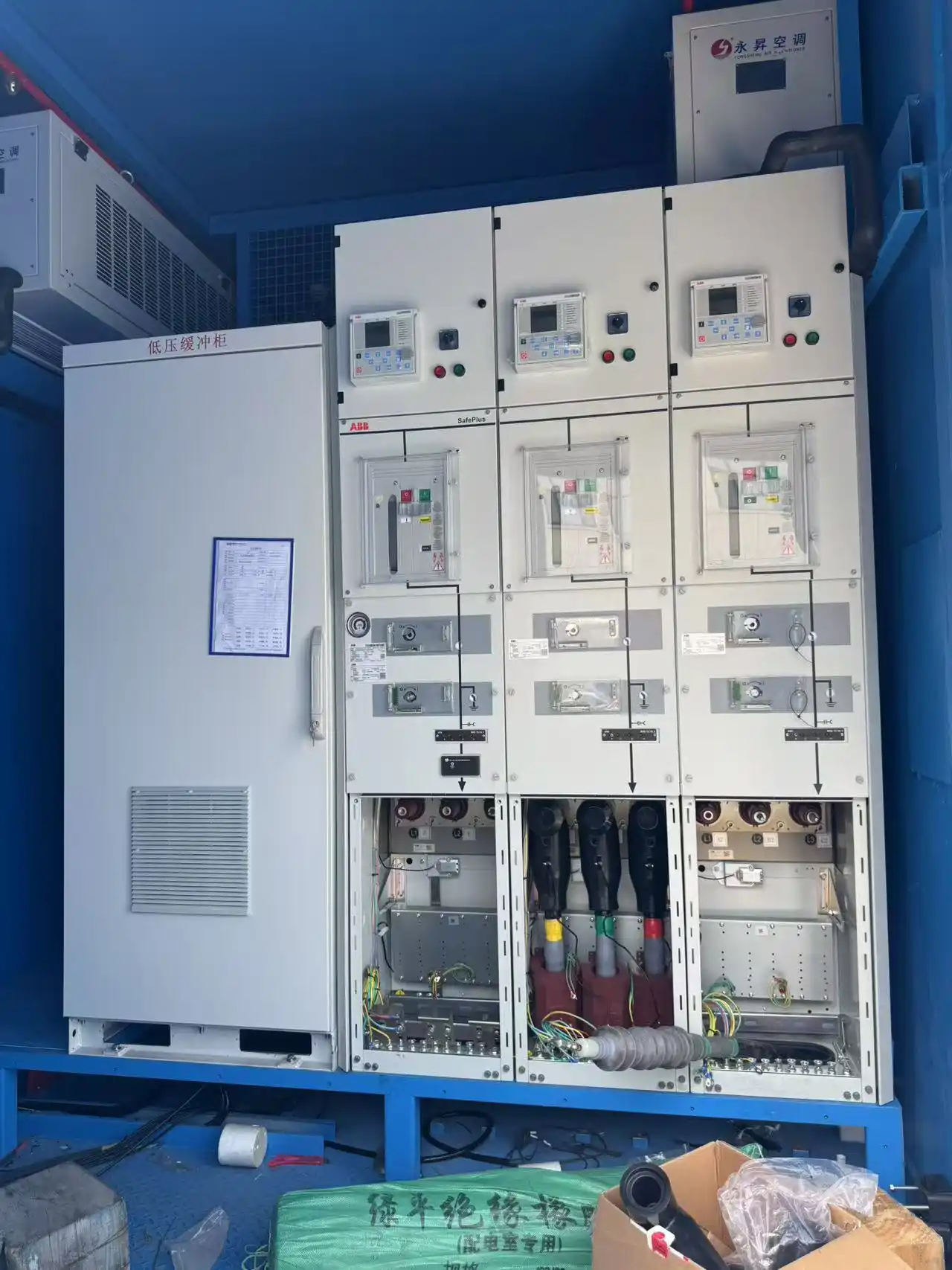
In one withdrawable-switchgear arrangement, loss of the equipotential circuit blocks breaker closing and prevents the breaker from entering its operating position.
If the circuit is lost during operation, the design uses a hardwired protective path to initiate breaker action while also sending the condition to the PLC.
A safety-critical bonding failure should not depend only on an HMI alarm or software message.
The required trip and permissive functions need a dependable electrical path and a defined fail-safe condition.
The exact response is configuration-dependent. A fixed switchboard, withdrawable breaker arrangement and other shore-power architectures may use different switching actions.
The project should therefore define what condition blocks energization, what happens if the bonding circuit is lost during operation, which protection action is hardwired, what the PLC records, and what condition is required before reconnection.
Contact Resistance and Maintenance Matter on Both Sides of the Connection
A connection that passes commissioning can deteriorate later.
Port-side sockets are exposed to repeated connection cycles and the marine environment. Contacts can corrode, oxidize or wear. Mechanical damage and poor storage can also change the quality of the connection.
The vessel side has the same problem.
The cable reel slip rings, shipboard plugs and sockets are also part of the protective path and need inspection and maintenance. Components with unacceptable contact resistance should be repaired or replaced.
Visual inspection is useful, but it does not prove the electrical condition of the complete path.
After the ship-to-shore cable is connected, the DC resistance of the connection system can be checked before energization. The result should be within the approved acceptance range.
For connection and interface requirements, see our shore power standards and compliance page.
An Isolation Transformer Does Not Replace the Protective Bonding Path
In one shore power configuration, an isolation transformer and a separate ship-to-shore equipotential protection circuit are both part of the system.
The isolation transformer separates the two electrical systems at the power-conversion level. The protective bonding connection addresses the conductive connection and safety interface between shore and vessel.
They are not interchangeable functions.
The transformer arrangement, neutral treatment, protective conductor and earth-fault protection should be reviewed together for the actual vessel and shore system. But the presence of an isolation transformer does not eliminate the need to verify the protective ship-to-shore connection.
Checks Before the First Energized Vessel Connection
The first live connection should not be the first time the protective interface is reviewed.
Before the first energized connection, check:
- the shore single-line diagram,
- the vessel single-line diagram,
- the protective-conductor arrangement,
- the condition of the plug and socket,
- the condition of the vessel cable reel and slip rings,
- the pilot-circuit wiring and status,
- the breaker permissive and trip logic,
- the protective trip / emergency shutdown interface,
- and the approved method for checking connection resistance.
These checks should form part of the commissioning and first-connection procedure.
The operator should also be able to identify why a permissive is missing. A specific indication such as a bonding-circuit or pilot-circuit fault is more useful than a generic “connection fault” message.
For the wider equipment-verification process, see our shore power manufacturing and FAT page.
Common Grounding and Bonding Errors
01 — Focusing only on protective-conductor size.
The complete bonding path also includes the connector, cable terminations, reel, slip rings and vessel-side bonding points. Any of these can introduce excessive resistance.
02 — Treating the pilot circuit as only a status indication.
When the pilot circuit forms part of the safety permissive, its failure changes whether the system is allowed to energize.
03 — Assuming a healthy pilot signal proves the physical connection is good.
It does not. Connector condition and resistance still need attention.
04 — Assuming an isolation transformer removes the need for equipotential bonding.
The two functions address different parts of the electrical safety design.
If the bonding permissive is missing or unstable, investigate the connection or interlock fault instead of bypassing the condition.
Information Needed for a Shore-to-Ship Bonding Review
To review the bonding and grounding interface, provide:
- Shore single-line diagram
- Vessel single-line diagram
- Connection voltage and frequency
- Transformer arrangement
- Plug and socket specification
- Protective-conductor arrangement
- Pilot-circuit details
- Cable and cable-reel arrangement
- Breaker and interlock philosophy
- Protective trip / emergency shutdown arrangement
- Connection and disconnection sequence
- Applicable standard or classification requirement
- Proposed connection-resistance acceptance method
This information allows the protective connection to be reviewed as part of the complete shore-to-ship interface rather than as an isolated grounding cable.
Frequently Asked Questions
Is the protective earth conductor the same as the neutral conductor?
No. The protective conductor belongs to the protective bonding path, while the neutral belongs to the electrical distribution arrangement. They should not be treated as interchangeable.
Can the shore power breaker close if the required pilot circuit is not proven?
Not in a control scheme where that pilot circuit forms part of the safety permissive. In the connection arrangement described above, loss of the equipotential circuit blocks breaker closing.
Why check connection resistance after the plug is inserted?
Because mechanical engagement does not by itself prove an acceptable electrical path. Contact condition, oxidation, wear and internal connection points can all increase resistance.
Does an isolation transformer remove the need for equipotential bonding?
No. Isolation and protective bonding perform different functions in the shore-to-ship electrical interface.
Who is responsible for the vessel-side cable and connector?
It depends on the project boundary. The operating procedure and supply scope should clearly assign inspection, maintenance and connection responsibility between the port, vessel and equipment team.
Discuss Your Shore-to-Ship Bonding Arrangement
Send us the shore and vessel single-line diagrams, connector details, protective-conductor arrangement, pilot circuit and intended switching sequence.
We can review the bonding path, pilot permissives and protection interface before the first energized vessel connection.
Send Your Connection Details