
Motor Starting, Unbalanced Loads and Shore Power Capacity
Do not confirm shore-power capacity from steady-state kW or kVA alone. Motor starting, overlapping restart sequences, transformer and cable impedance, converter current-time capability and phase imbalance can all change the real electrical condition seen by the vessel.
Why Steady-State kW or kVA Is Not Enough
A normal load calculation answers one important question:
Motor starting creates a different question:
A vessel may operate comfortably below the continuous rating of the shore supply and still create a demanding short-duration event when a large pump or compressor starts.
The result depends on several factors at the same time:
- motor starting current;
- acceleration time;
- load already connected;
- simultaneous or automatic restart;
- transformer and cable impedance;
- temporary converter capability;
- phase loading.
A fixed percentage margin should not replace a review of the actual dynamic event.
What Happens to the Shore Supply When a Large Motor Starts?
Motor starting is often reduced to one number: starting current.
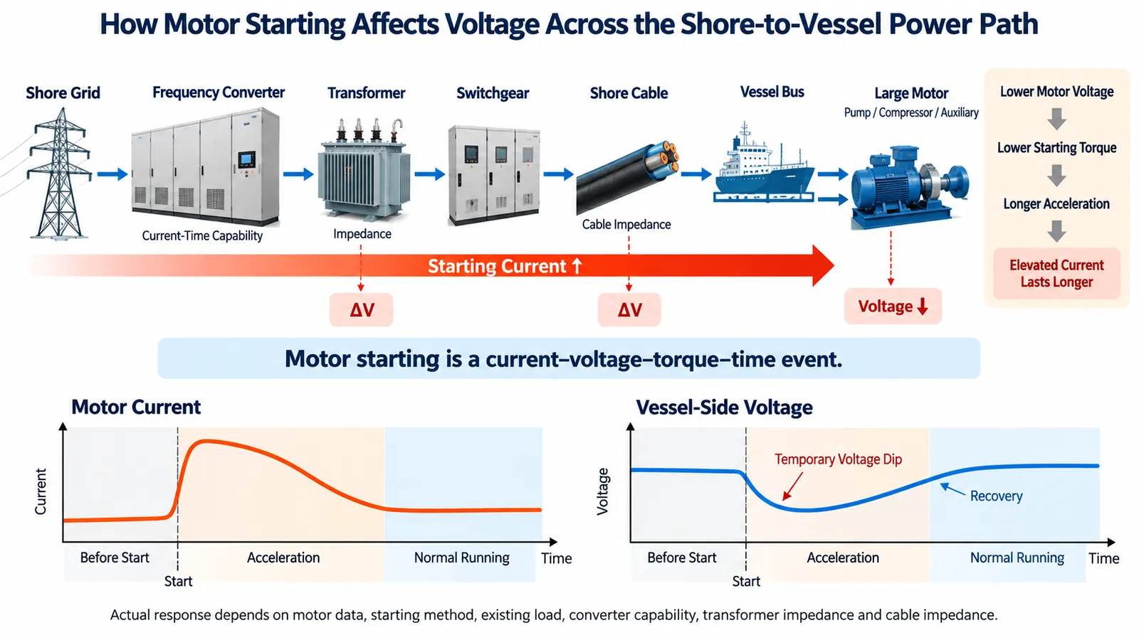
That is not enough. The event involves current, voltage, torque and time.
When a large induction motor starts, its current rises above the normal running level. That current flows through the impedance of the supplying system, creating a temporary voltage drop along the electrical path.
If the motor-terminal voltage falls too far, the available starting torque also falls. Acceleration can then take longer, allowing the elevated-current condition to persist for longer.
The engineering question is not simply how high the current becomes. It is whether the motor can accelerate successfully while the shore-power system remains within an acceptable electrical operating condition.
Use the Actual Motor Data
The starting-current value should come from the actual motor and starting method whenever that information is available.
Useful inputs include:
- motor rated current;
- motor power;
- starting method;
- expected starting current;
- acceleration time;
- driven equipment.
Two motors with similar running power can impose very different demands if they use different starting methods or drive different mechanical loads.
Lower Starting Current Is Not Automatically a Better Start
Reduced-voltage starting or a soft starter can reduce the current peak seen by the shore supply. At the same time, the available starting torque changes.
If current or starting voltage is restricted too aggressively, the motor can accelerate more slowly. In a poor case, the available acceleration torque may be insufficient for the driven load.
Soft-starter settings therefore have to match both the motor and the mechanical load. The target is not minimum starting current. The motor has to accelerate successfully without creating an unacceptable disturbance in the shore-power system.
Motor-Start Voltage Depends on the Complete Shore-to-Vessel Path
A motor does not operate directly from the converter nameplate.
The electrical path may include the shore grid, frequency converter, transformer, switchgear, shore cable, shore-to-ship connection, vessel distribution and the motor itself. Every part of that path can influence the voltage available during a high-current event.
The marine frequency converter is one part of this complete source path; its temporary current capability has to be considered together with the downstream electrical system.
Transformer Impedance Affects the Result
Transformer impedance contributes to the voltage drop during motor starting.
Lower impedance can improve voltage stiffness, but it is not automatically the better design choice. Transformer impedance also affects available fault current and therefore interacts with switchgear ratings and protection coordination.
Motor-start performance cannot be the only criterion for transformer selection.
Cable Length and Conductor Size Also Matter
Long cable runs and high current can create additional voltage drop between the shore equipment and the vessel.
Increasing conductor size can reduce the drop, but it also affects cable cost, weight, routing, handling and connection arrangements.
Where voltage-drop compensation is provided, it can support downstream voltage regulation. It does not remove the need to check conductor current capacity, cable impedance and protection requirements.
The Control Point and the Vessel Load Point May Be Different
The point where voltage is measured or regulated is not always the same electrical point where the vessel load experiences the lowest voltage.
In one 630 kVA shore-power configuration, voltage feedback was taken at the output of the isolation transformer. The downstream cable and connection path still had to be considered separately.
Capacity Is Also a Current-Time and Sequence Problem
Converter overload capability is often reduced to one percentage. A percentage alone is incomplete.
Temporary capability has to be considered together with duration and operating condition.
In one 630 kVA shore-power configuration, temporary overload capability was specified as 110% for one hour and 130% for one minute. These values are project-specific, but they show why overload magnitude and duration must be considered together.
For motor starting, the actual load event has to be compared with the permitted current-time capability of the source.
A short current excursion may remain acceptable. A similar current sustained for much longer because the motor accelerates slowly can produce a different result.
Several Overlapping Restarts Can Be More Demanding Than One Isolated Motor Start
The largest individual motor is not always the most demanding operating condition.
After connection to shore power, several vessel auxiliaries may restart within the same period. A simplified sequence could include:
- one pump already running;
- a cooling pump starting;
- a compressor restarting;
- ventilation equipment returning to service;
- other auxiliaries following shortly afterward.
If those events overlap, the shore supply sees the combined dynamic demand. The operating sequence therefore belongs in the capacity review.
Load Sequencing Can Reduce Simultaneous Demand
Where vessel operations permit, some loads can be restarted in stages. This can reduce simultaneous dynamic demand without changing the motor itself.
But not every load can be delayed. Essential equipment may require immediate restart, and some vessels already have fixed automatic restart logic.
A dynamic-load problem can therefore lead to several different engineering responses:
- change the starting method;
- change the restart sequence;
- reduce excessive voltage drop in the electrical path;
- increase source capacity;
- revise the system architecture.
The correct response depends on what is actually limiting the system.
Why Total Three-Phase kVA Can Hide a Phase Limitation
Total three-phase kVA can appear acceptable while one phase becomes the limiting condition first.
This matters when the vessel contains uneven single-phase loads or when downstream distribution is significantly unbalanced.
A capacity review may therefore need to consider:
- individual phase currents;
- individual phase voltages;
- voltage unbalance;
- current unbalance.
Abnormal phase conditions can have direct consequences for connected motors.
A UK Marine Accident Investigation Branch safety digest documented a shore-supply failure in which one phase was lost because of a poor connection. Motors onboard the vessel subsequently operated under single-phasing conditions, and some were damaged.
That event was not caused by motor starting and does not define an acceptable unbalance percentage. It does show that abnormal phase conditions can have real equipment consequences.
In one shore-power test plan, output-voltage unbalance and a defined three-phase impedance-unbalance condition were verified separately from normal balanced loading.
Total three-phase capacity therefore does not prove that every phase remains within an acceptable operating condition.
What Real Shore-Power Projects Show About Dynamic Loads
Project evidence is most useful when it explains why a particular engineering requirement exists.
A 630 kVA Configuration
In one 630 kVA shore-power configuration, the requirements separately addressed continuous loading, temporary overload duration, voltage and frequency transient recovery, and unbalanced operating conditions.
The overload specification used separate magnitude-and-time points rather than one general overload percentage. The same configuration also defined measurable transient-response requirements.
Dynamic performance can therefore be treated as a defined and verifiable project requirement rather than a general statement that the system is “stable.”
A 5 MVA High-Voltage Project
In one 5 MVA high-voltage shore-power project, the vessel was carrying approximately 1.5 MW on its onboard generation before transfer to shore power.
After the load was transferred, several onboard pump-start events were carried out while the shore-power equipment remained in service.
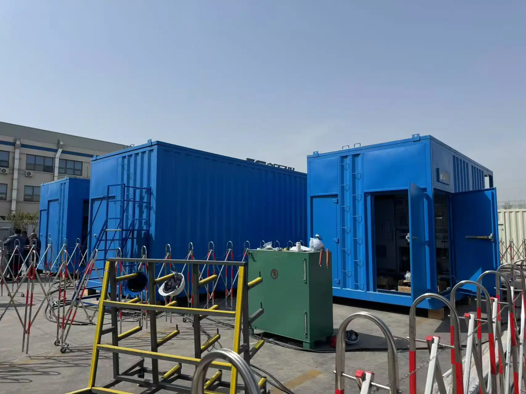
Large onboard load changes were therefore part of the actual vessel connection and commissioning condition, not only a theoretical sizing case.
This does not mean that every 5 MVA shore-power system can start every large pump. The result still depends on the motor rating, starting method, running load, electrical path and operating sequence.
How Should Dynamic Load Adequacy Be Verified?
A 100% load test answers only part of the capacity question. Dynamic conditions need their own verification where they are critical to the design.
1 Review the Vessel Data
Start with the actual operating information:
- normal running load;
- largest motors;
- starting methods;
- automatic restart logic;
- simultaneous loads;
- operating sequence.
Without this information, the analysis depends heavily on assumptions.
2 Calculate or Simulate the Critical Event
The review may need to consider:
- starting current;
- starting duration;
- existing running load;
- transformer impedance;
- cable impedance;
- expected voltage during the event;
- converter current-time capability.
Where acceleration is critical, motor speed and torque behaviour may also need to be considered.
3 Verify the Agreed Dynamic Conditions
Factory or system testing can confirm relevant characteristics such as load changes, temporary overload, transient voltage response, transient frequency response and phase-unbalance behaviour.
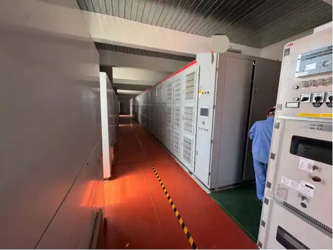
A continuous full-load test remains important, but it proves a different part of source capability.
| Verification | What It Helps Confirm |
|---|---|
| Continuous full-load test | Thermal and continuous operating capability |
| Temporary overload test | Short-duration current capability |
| Dynamic load change | Voltage and frequency response |
| Unbalance test | Per-phase behaviour |
| Vessel motor start | Actual operating sequence |
Each critical dynamic design assumption should have a corresponding verification method.
Detailed overload and step-load procedures belong in the test plan rather than in the capacity calculation itself.
4 Confirm Real Vessel Behaviour Where Required
Final vessel commissioning can provide another verification layer when the result depends strongly on actual onboard loads, restart logic, final cable arrangement or operating sequence.
What Data Should Be Reviewed Before Shore-Power Capacity Is Confirmed?
A useful capacity review requires more than total vessel kW.
Vessel Load
- normal running kW or kVA;
- maximum demand;
- power factor.
Largest Motors
- motor power;
- rated current;
- starting method;
- starting current, if available;
- acceleration time;
- driven equipment.
Operating Sequence
- load already running before the motor starts;
- motors that can start simultaneously;
- automatic restart loads;
- essential loads;
- loads that can be delayed.
Electrical Path
- shore voltage and frequency;
- transformer arrangement;
- transformer impedance;
- cable length;
- conductor size;
- vessel connection point.
Acceptance Requirements
- allowable voltage condition during the event;
- required dynamic verification;
- FAT or SAT requirements;
- vessel commissioning requirements.
Possible Review Outcomes
The critical load event remains within the available electrical margin.
The source remains unchanged, but overlapping restart demand is reduced.
The motor-starting method, restart sequence or electrical path is adjusted without necessarily increasing the source rating.
The actual vessel event still exceeds acceptable current, voltage or duration limits after practical operating changes are considered.
Capacity should therefore be confirmed from the actual dynamic event rather than from a fixed percentage margin alone.
Frequently Asked Questions
Is total vessel kW enough to size a shore-power system?
No. Total kW or kVA is necessary for continuous-load sizing, but motor starting, load sequence, source impedance and phase loading can create a different dynamic requirement.
How much motor starting current should be assumed?
Use the actual motor and starting-method data where available. Generic multipliers may help during an early estimate, but final capacity review should use manufacturer data or project-specific starting characteristics whenever possible.
Does a soft starter always reduce the required shore-power capacity?
No. A soft starter can reduce the current peak, but it also changes starting torque and acceleration time. The result depends on the motor, driven load, existing vessel load and source path.
Is a 100% load test enough to verify large-motor starting?
No. A continuous full-load test verifies continuous operation. Motor starting is a dynamic current-and-voltage event and may require separate verification.
Can load sequencing avoid increasing shore-power capacity?
Sometimes. Where vessel operations allow non-critical loads to restart in stages, simultaneous dynamic demand can be reduced. Essential loads and fixed vessel control logic may limit how much the sequence can be changed.
Technical References
- IEC/IEEE 80005-1:2019 — Utility connections in port — Part 1: High Voltage Shore Connection systems .
- IEC/IEEE 80005-3:2025 — Utility connections in port — Part 3: Low Voltage Shore Connection systems .
- ABB — Motor Starting Analysis .
- Siemens — SIRIUS 3RW30 / 3RW40 Soft Starters .
- Schneider Electric — Reduced Voltage Starting of Squirrel Cage Motors .
- ABB — 630 Series Technical Manual, motor unbalance and negative-sequence effects .
Incident Reference
- UK Marine Accident Investigation Branch — Safety Digest, Volume 2 / 2010 , shore-supply phase-loss case involving motor single-phasing.
Review the Real Vessel Load Sequence Before Confirming Capacity
Shore-power capacity should be confirmed against the vessel's real operating condition, not only its normal load.
Send the vessel load list, largest motor data, starting methods, restart sequence, transformer arrangement and cable route. We can review the dynamic load condition before the shore-power capacity and architecture are frozen.
Send Project Requirements