
Shore Power Transformer Vector Groups and Grounding
A transformer can have the correct kVA rating and the correct 400 V or 440 V output and still be the wrong electrical interface for a vessel. Vector group, neutral availability, grounding, protection and transfer method have to be reviewed together.
A shore power transformer vector group should not be selected from voltage and kVA alone. The correct arrangement depends on how the shore source, transformer and vessel network interact electrically.
- Does the vessel require a neutral conductor?
- How is that neutral referenced to earth?
- What phase relationship exists at the vessel-side bus?
- Will shore and vessel sources operate in temporary parallel?
- How will earth faults be detected?
- What zero-sequence quantities will the protection system see?
- Does the final transformer impedance still match the fault study?
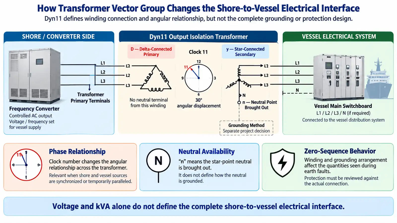
Why Transformer Vector Group Becomes a Shore-to-Ship Interface Problem
A shore connection joins two electrical systems that were originally designed independently.
On the shore side, the system may already include a utility source, frequency converter, phase-shifting and isolation transformers , switchgear, grounding, protection, metering and control.
On the vessel side, there may already be generators, a main switchboard, existing transformers, an established neutral and grounding arrangement, protection relays and a defined transfer method.
The transformer sits between these two systems. Its winding connection therefore affects more than voltage conversion.
It can define the phase relationship between primary and secondary, determine whether a neutral point is available, and influence how zero-sequence quantities appear during an earth fault.
In one 630 kVA low-voltage shore power system, the electrical path included a frequency-conversion system, output isolation transformer, low-voltage switchgear, berth connection equipment and the vessel interface.
The transformer therefore formed part of the vessel-facing electrical system rather than a standalone component selected only by rating.
For the wider relationship between these components, see the shore power system architecture .
IEC/IEEE 80005-3:2025 treats low-voltage shore connection as a complete shore-to-ship system involving transformers, converters, ship-side equipment, protection, control, monitoring and interlocking.
IMO MSC.1/Circ.1675 also emphasizes ship/shore compatibility, earthing, protection and integration testing.
The practical question is not simply: “Is this a 630 kVA, 440 V transformer?”
“Will this transformer create the correct electrical interface between this shore system and this vessel?”
What Dyn11 Tells You — and What It Does Not
Dyn11 is a transformer connection designation.
The symbols describe the winding relationship:
- D — delta-connected winding.
- y — star-connected winding.
- n — the star point is brought out as a neutral terminal.
- 11 — the angular relationship defined by transformer clock notation.
Dyn11 represents a 30-degree angular displacement between the two windings.
But the vector-group code does not define the complete shore-power interface.
A Dyn11 nameplate does not tell you:
- whether the neutral is solidly grounded;
- whether it is grounded through an impedance;
- what earth-fault current is expected;
- where zero-sequence quantities are measured;
- how the vessel itself is grounded;
- whether shore and vessel sources will be synchronized;
- whether the selected connection matches the vessel-side protection philosophy.
The vector group therefore defines only part of the complete grounding and protection interface.
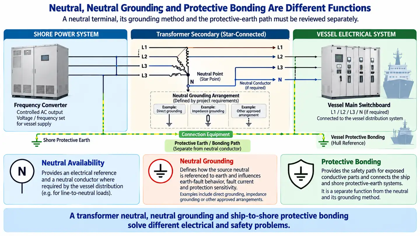
An Available Neutral Does Not Define the Grounding Method
The “n” in Dyn11 tells you that a neutral point is available. It does not define how that point is connected to earth.
Does the vessel actually need a neutral?
The answer depends on the vessel distribution system.
A neutral may be required where the vessel uses a four-wire system or has line-to-neutral loads. In another application the neutral terminal may exist but not be used as a load conductor.
Confirm this from the vessel single-line diagram.
How is the neutral referenced to earth?
Once a neutral exists, its grounding method still has to be selected separately.
- vessel grounding philosophy;
- required earth-fault current;
- fault-detection method;
- protection sensitivity;
- continuity requirement;
- project and class requirements.
The more useful design question is:
“How should an earth fault behave in this particular shore-to-vessel network?”
In another shore-power configuration, an impedance-grounded neutral was coordinated with zero-sequence protection so that a single-line-to-ground fault could be detected and isolated.
The same arrangement is appropriate only where the required earth-fault behavior and protection philosophy support it.
Neutral grounding should also be kept separate from ship-to-shore protective bonding , which serves a different safety function.
How Winding Connection and Grounding Change Earth-Fault Protection
Grounding design and protection design cannot be treated independently.
During an earth fault, the protection system only sees the electrical quantities that the actual network makes available.
That depends on:
- transformer winding connection;
- neutral grounding;
- fault-current return path;
- CT location;
- PT location;
- relay measurement logic.
For a grounded star–delta transformer, an external earth fault can produce zero-sequence current on the star side without the same line-current component appearing on the delta side.
If differential protection does not account for that relationship correctly, false differential current and unwanted operation can result.
Follow the actual fault path:
- Where does the earth fault occur?
- What path allows the fault current to return?
- Which neutral point is connected to earth?
- What zero-sequence voltage or current is created?
- Where is that quantity measured?
- What does the protection relay interpret?
If these questions are not answered, a relay setting that appears reasonable on paper may still be wrong for the installed network.
Possible consequences include:
- nuisance trips;
- incorrect earth-fault sensitivity;
- false residual or differential quantities;
- failure to obtain the expected fault indication;
- failed commissioning protection tests.
A Real 630 kVA Dyn11 Shore Power Configuration
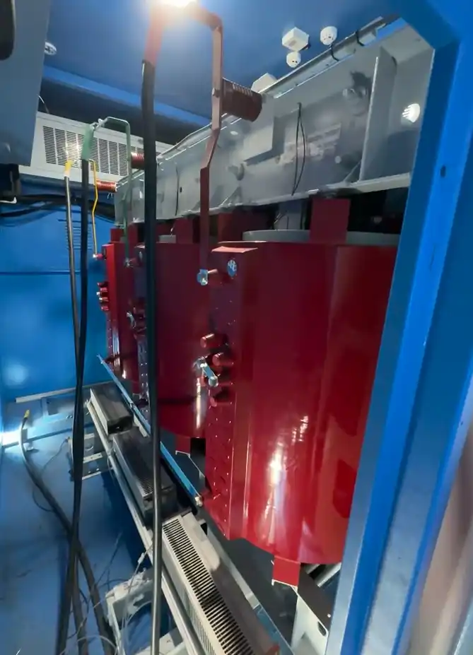
In one 630 kVA low-voltage shore power system, a dry-type Dyn11 output isolation transformer operated downstream of the frequency-conversion system.
The system also included high- and low-voltage switchgear, metering, berth connection equipment, monitoring and protection.
Because output-voltage feedback was taken after the isolation transformer, the transformer formed part of the controlled vessel-side output boundary.
The same configuration included synchronized load transfer between shore and vessel power, so the transformer phase relationship also formed part of the transfer interface.
This is one practical Dyn11 application. A vessel with the same nominal voltage can still require a different connection because its neutral, grounding, protection or transfer arrangement may be different.
Similar Vessel Voltage Does Not Mean Identical Transformer Architecture
Two shore-power systems can supply similar vessel voltages while using different upstream architectures.
| Configuration | Shore-Side Architecture | Vessel-Side Output |
|---|---|---|
| 630 kVA | Frequency converter + phase-shifting transformer + output isolation transformer | 400 V / 50 Hz or 440 V / 60 Hz |
| 500 kVA | 6/6.6 kV source + isolation transformer | 400/440 V vessel supply |
Both arrangements can reach a similar low-voltage vessel interface, but their upstream power paths are different.
That difference can change transformer roles, protection studies, synchronization requirements, grounding review and short-circuit calculations.
A copied transformer specification may therefore be correct on the voltage line while still being wrong at the system level.
Why Vector-Group Phase Displacement Matters During Synchronized Transfer
Phase displacement becomes especially important when the vessel transfers load without a complete interruption.
Break-before-make transfer
One source is disconnected before the other is connected.
This avoids temporary source paralleling but introduces a supply interruption.
The detailed switching sequence is covered in the shore power connection procedure .
Synchronized or no-break transfer
The vessel source and shore source are synchronized before the load is transferred.
This can maintain continuity but creates a more demanding electrical interface.
Before two energized AC systems are tied together, engineers need to understand the actual conditions at the intended breaker or tie point:
- voltage;
- frequency;
- phase sequence;
- phase angle;
- transformer position between the measurement points.
The transformer clock number matters because it changes the phase relationship between the source on one side and the voltage measured on the other.
The useful question is not:
“Does Dyn11 have a 30-degree displacement?”
It is:
“What phase relationship exists at the actual synchronization points in this system?”
Closing or temporarily paralleling energized sources with excessive phase-angle or frequency mismatch can produce large transient currents, rapid power exchange and high electrical or mechanical stress.
Even when closing is blocked by protection, the same mismatch can prevent a successful no-break transfer.
A synchronized transfer also requires review of permissible power flow and, where applicable, reverse-power protection during shore-to-ship transfer .
No-break transfer improves continuity, but it also increases requirements for synchronization logic, measurement accuracy, phase-reference review and protection coordination.
Vector Group Is Not the Only Transformer Parameter That Affects the Interface
Transformer percentage impedance is also part of the downstream system study.
In one 630 kVA converter-based configuration, the short-circuit study was divided into:
- the upstream side of the converter;
- the controlled output and vessel side.
The output isolation transformer impedance was included in the vessel-side calculation.
Transformer impedance influences fault current, breaker duty, protection coordination, downstream fault level and, depending on the application, voltage performance.
It also creates a procurement risk. If the engineering calculation uses one transformer impedance and the purchased transformer later uses another value, the original fault study may no longer represent the installed system.
The final transformer data should therefore be frozen together with the short-circuit and protection basis.
Lower impedance is not always better, and higher impedance is not automatically safer.
Detailed calculation methods are covered in shore power short-circuit current calculation .
How to Verify the Transformer Interface Before Vessel Connection
A correct transformer interface is not proven by the nameplate alone. Each design assumption needs a corresponding verification point.
| Design Assumption | Verification Method |
|---|---|
| Vector group | Nameplate, terminal diagram and transformer test record |
| Phase sequence | Phase-sequence test at the actual output |
| Neutral availability | Terminal and wiring inspection |
| Grounding arrangement | Neutral-to-earth connection verification |
| Earth-fault measurement | Zero-sequence simulation or functional test |
| Protection response | Relay or functional protection test |
| Transformer impedance | Approved datasheet + calculation review |
| Synchronized transfer | Functional synchronization and transfer test |
The objective is not simply to verify a transformer.
It is to verify that phase relationship, grounding, protection and transfer behavior match the approved shore-to-vessel electrical interface.
A Practical Workflow for Selecting the Transformer Vector Group
Review both shore and vessel SLDs
Identify the complete source-to-vessel power path before starting from a transformer datasheet.
Confirm voltage, frequency and load requirement
Establish source voltage, vessel voltage, 50/60 Hz requirement, transformer kVA and significant loads.
Confirm whether a neutral is required
Determine the three-wire or four-wire interface and any line-to-neutral load requirement.
Define grounding and earth-fault philosophy
Review vessel grounding, required fault-current behavior, protection method and applicable project/class requirements.
Define the transfer method
Confirm break-before-make, synchronized no-break or temporary parallel operation and identify the real synchronization points.
Select transformer connection and impedance
Freeze winding connection, vector group, neutral terminal, voltage ratio and percentage impedance only after the interface conditions are understood.
Recheck protection, fault study and verification plan
Confirm that the final transformer data remains consistent with the calculation, earth-fault protection, transfer logic and commissioning tests.
What Project Data Should Be Provided Before the Vector Group Is Frozen?
A transformer RFQ containing only 630 kVA, 440 V, 60 Hz and Dyn11 is not enough for a complete shore-power interface review.
Shore-side data
- Shore single-line diagram
- Supply voltage and frequency
- Available source fault level
- Frequency-converter topology and output
- Shore-side protection arrangement
Vessel-side data
- Vessel single-line diagram
- Main switchboard arrangement
- Generator configuration
- Shore incomer arrangement
- Operating voltage and frequency
- Major load information
Transformer data
- Required kVA
- Primary and secondary voltage
- Proposed vector group
- Required neutral
- Proposed percentage impedance
- Isolation requirement
Grounding data
- Vessel grounding philosophy
- Existing neutral-to-earth arrangement
- Required earth-fault behavior
- Ground-fault protection concept
Transfer and protection
- Break-before-make or synchronized transfer
- Temporary parallel requirement
- Synchronization point
- CT and PT locations
- Earth-fault / overcurrent protection
- Reverse-power requirement where applicable
Compliance
- Applicable shore power standards and compliance
- Classification-society requirements
- Port or owner-specific specifications
Frequently Asked Questions
Is Dyn11 required for a 400 V or 440 V shore power system?
No. Voltage alone does not determine the transformer vector group. The vessel network, neutral, grounding, protection and transfer arrangement also have to be considered.
Does the “n” in Dyn11 mean the neutral is grounded?
No. It means the star point is brought out as a neutral terminal. Grounding is a separate design decision.
Why does the Dyn11 clock number matter in shore power?
The clock number defines the angular relationship between the transformer windings. That becomes important when shore and vessel voltage references are compared during synchronized or temporary parallel operation.
How does transformer connection affect earth-fault protection?
Winding and grounding arrangement changes the zero-sequence quantities available to residual or differential protection and can therefore change earth-fault sensitivity and coordination.
Does an isolation transformer remove the need for ship-to-shore protective bonding?
No. Electrical isolation and protective bonding perform different functions. Both arrangements still have to be reviewed as part of the complete connection.
Technical References
- IEC/IEEE 80005-3:2025 — Utility connections in port — Low-voltage shore connection systems.
- IMO MSC.1/Circ.1675 — Interim Guidelines on Safe Operation of Onshore Power Supply Service in Port.
- IEC 60076-1 — Power Transformers — Part 1: General.
- ABB — Transformer Protection Fundamentals — vector groups, zero-sequence behavior and differential protection.
- Schneider Electric — transformer vector-group, phase-displacement and parallel-operation guidance.
- GE Vernova — generator protection and synchronization application guidance.
Review the Transformer Interface Before Freezing the Vector Group
Send the shore and vessel single-line diagrams together with the required voltage, neutral arrangement, grounding philosophy and transfer method.
We can review the transformer interface together with the protection and fault-study basis before the final specification is frozen.
Send Project Electrical Data