
Shore Power Connection Procedure: From Cable Check to Vessel Transfer
A safe shore power connection is a controlled operating sequence, not a plug-in action.
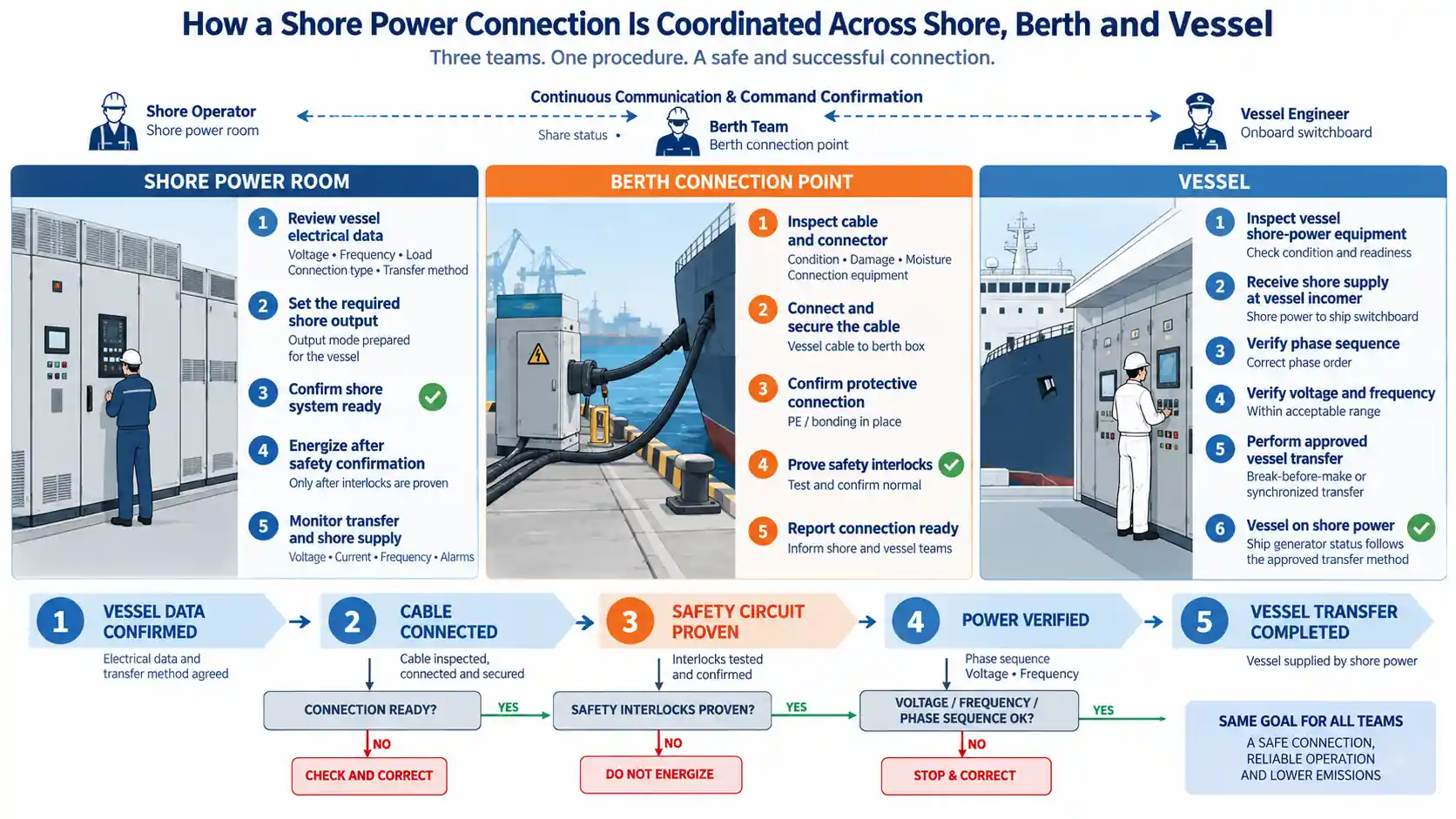
Before power reaches the vessel, the port and ship have to confirm electrical compatibility, inspect the connection equipment, establish clear operating responsibility, prove the protective and interlock circuits, verify the incoming power and complete the agreed transfer method.
The switching sequence changes depending on whether the vessel uses break-before-make transfer or synchronized no-break transfer. That decision should already be clear before the vessel is connected. It affects the shipboard equipment, synchronization requirements, protection and operating procedure.
The same discipline applies when shore power is disconnected. Removing the plug is the final step, not the first.
Confirm Vessel Data and Operating Roles Before Arrival
The connection procedure begins before the vessel reaches the berth.
The port needs enough information to prepare the shore power system for the actual vessel. At minimum, confirm:
- Vessel name
- Required voltage
- Required frequency
- Expected shore power demand
- Shore connection type
- Connection-point location
- Responsible shipboard contact
- Planned period of shore power use
- Intended transfer method
For a first connection, additional electrical information may be required, including the vessel single-line diagram, neutral arrangement, shore incoming switchboard, onboard transformer and synchronizing arrangement.
In one project procedure, vessel data was submitted 24 hours before arrival. That was an operating rule for that project, not a universal requirement for every port. Each terminal should define a lead time that gives the operating team enough time to review the vessel and prepare the system.
For the electrical information that should be exchanged during early project and vessel compatibility review, see our shore power selection and compatibility guide .
The procedure should also identify who is responsible at each operating location. For many installations, the critical locations are:
- The shore power room
- The berth connection point
- The shipboard switchboard
Each location needs an identified operator and a dependable communication method. Switching commands should be confirmed before action is taken. The procedure also needs to state who can stop the sequence, who authorizes energization and who controls the response after a trip or emergency stop.
A technically correct connection can still become unsafe if different teams are acting on different assumptions.
Inspect Shore, Vessel and Connection Equipment
Do not begin cable connection only because the vessel has the correct plug.
On the shore side, inspect the berth connection box, plug or socket, cable equipment, mechanical supports and the equipment needed for the planned power path.
Look for conditions that can affect the connection:
- Moisture or salt deposits
- Damaged insulation
- Contaminated or damaged contacts
- Loose hardware
- Missing covers or seals
- Abnormal cable condition
- Damage to the cable reel or cable-management equipment
The vessel side also needs to be ready.
For a first connection, one project procedure required the ship to check its high-voltage cable, cable reel, incoming and outgoing switchgear and onboard transformer before the shore connection proceeded.
The vessel shore incoming switchboard and associated equipment should be in the state required by the approved operating procedure.
A connector can be mechanically compatible while the vessel electrical system is still not ready to receive power.
The relationship between the converter, transformers, switchgear and berth connection can be seen in our shore power system architecture and components guide.
Connect the Cable and Prove the Safety Interlocks
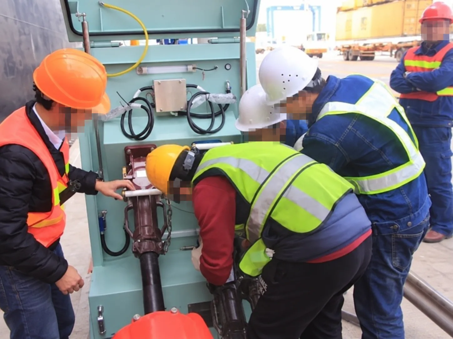
Cable reach and mechanical loading should be checked before the connector is inserted.
Vessel position changes with tide, loading and mooring conditions. The cable therefore needs an arrangement that allows the required movement without placing excessive mechanical force on the electrical connector.
Use the intended cable supports and cable-management equipment. The connector should not be used as the main mechanical support for the cable.
Once the cable is connected and secured, the electrical safety conditions still have to be proven.
The protective earth or equipotential connection should be established as required by the connection design before the phase conductors are energized. Pilot contacts and associated safety circuits can then confirm that the connector and required protective conditions are in the correct state.
In one shore power procedure, the operating team performed a safety-interlock circuit test after the berth cable had been connected. Energization was allowed only after the safety circuit was confirmed normal.
Another engineering procedure required the DC resistance of the connected interface to be measured after the ship-to-shore cable was connected. Power could be applied only when the result was within the approved range.
The acceptance value should come from the actual connection equipment and project procedure. A resistance value from another port should not simply be copied into a new project.
The cable is not electrically ready just because the plug is physically inserted.
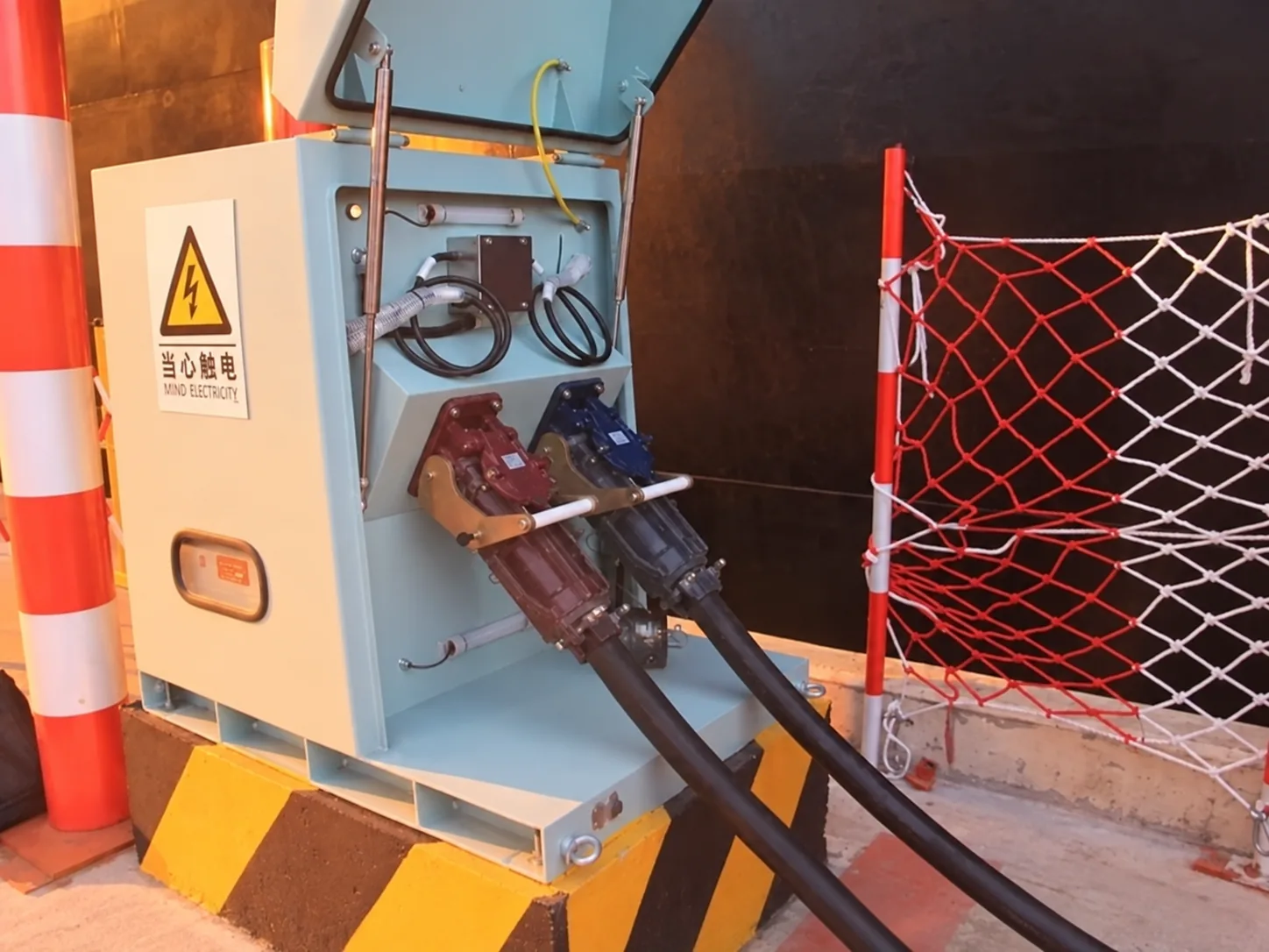
For the protective conductor, pilot circuit and equipotential-bonding logic behind this step, see our ship-to-shore equipotential bonding and grounding guide.
Verify Voltage, Frequency and Phase Sequence Before Transfer
After the connection and safety circuits are proven, the shore supply can be prepared according to the approved switching procedure.
Before the vessel accepts the supply, confirm the electrical conditions at the vessel interface.
The required checks include:
- Voltage
- Frequency
- Phase sequence
- Required breaker and interlock status
In one high-voltage vessel connection procedure, shore power was first brought to the incoming side of the vessel main switchboard. The shipboard operators then checked phase sequence, voltage and frequency before allowing the transfer to continue.
If the values are not acceptable, stop the sequence and correct the condition using the approved adjustment method.
In that converter-based system, the shore power converter could be used to adjust phase sequence and output voltage or frequency before transfer. That capability belongs to the specific converter and control arrangement. It should not be assumed for every shore power system.
The marine frequency converter therefore does more than change one nominal frequency into another. Its actual control range, output configuration and permissible adjustment method should be confirmed for the selected system.
For synchronized transfer, matching nominal voltage and frequency is not by itself enough. The synchronization equipment and approved control logic must establish the conditions required before temporary parallel operation is permitted.
Select the Correct Vessel Transfer Method
There are two fundamentally different ways to move a vessel from onboard generation to shore power.
Break-Before-Make Transfer
With break-before-make operation, the existing source is disconnected before the new source supplies the relevant bus.
The sequence avoids intentional parallel operation between the ship generator and shore supply, but it can create an interruption unless critical loads are supported by another approved source.
Whether that interruption is acceptable depends on the vessel and its operating requirements.
Synchronized No-Break Transfer
With synchronized transfer, shore power and the vessel generator are brought into acceptable synchronization before the two sources are temporarily connected in parallel.
The vessel load is then transferred from the onboard generator to shore power before the generator is taken offline.
This requires more than a shore-side breaker command.
The complete transfer can involve:
- Vessel synchronizing equipment
- Generator controls
- Shore power converter control
- Ship and shore breakers
- Protection systems
- Communication between operating teams
Temporary parallel operation also introduces the possibility of reverse power if the two sources or the load transfer are not correctly coordinated.
That issue should be treated as a separate protection and control problem rather than hidden inside the basic connection procedure.
Not every vessel requires no-break transfer. The selected method should follow the vessel electrical arrangement and the agreed operating requirement.
Transfer the Load and Monitor the First Minutes
Closing the required breaker does not mean the transfer is finished.
The operating team should watch the electrical system while the load moves from the vessel generator to shore power.
Useful observations include:
- Shore power voltage
- Current
- Frequency
- Active power
- Breaker status
- Protection status
- Converter alarms
- Vessel load behavior
Large pumps, fans or other significant loads may create changes that were not visible before the vessel began normal operation.
In one 6.6 kV shore power project in which SDACME participated with project partners, the vessel generators were carrying approximately 1,500 kW before the transfer. During the connection test, the control sequence transferred the vessel load to shore power in approximately 30 seconds, after which the ship generator was taken offline.
The vessel also carried out multiple onboard pump-starting tests during the shore connection, while the shore power equipment remained in operation.
The 30-second result is a record from that project. It is not a required transfer time for another vessel or another shore power system.
Transfer time depends on the vessel, generator controls, synchronizing system, operating sequence and project requirements.
Before routine connection begins, protection, interlocks and load-related behavior should already have been verified through the agreed commissioning process. Our shore power load testing and acceptance guide explains what should be checked before the first vessel connection.
Disconnect Through an Approved Operating Procedure
Leaving shore power also requires a defined sequence.
The crew and shore operator should first confirm how the vessel will take back its electrical load. If the ship generator has to be returned to service, that transition should follow the approved vessel operating method.
The shore supply should then be removed and placed in the required isolated safe condition before personnel are allowed to release the electrical connection.
Disconnection is also a switching procedure—not simply unplugging the cable.
The actual switching sequence depends on the switchgear, earthing arrangement, cable equipment and vessel interface.
The procedure should therefore state:
- Who authorizes the transfer away from shore power
- When the shore output is considered isolated
- How the de-energized condition is confirmed
- Which interlocks must return to the safe state
- When the connector may be released
- Who confirms the operation is complete
The project documentation reviewed for this article included separate shore-power energization and de-energization confirmation records and required switching to follow the approved operating procedure.
That is the correct principle to carry into a new project: define the switching boundary and responsibility before routine operation starts.
What Should Be Fixed in the Connection Procedure?
A repeatable shore power connection should not depend on the memory of the operator who handled the previous vessel.
The written procedure should identify:
- Required vessel data before arrival
- Shore and vessel operating responsibilities
- Communication method
- Equipment inspection points
- Cable-handling requirements
- Protective earth and equipotential checks
- Pilot and safety-interlock verification
- Voltage, frequency and phase-sequence checks
- Break-before-make or synchronized transfer method
- Generator and breaker operating responsibility
- Required monitoring during load transfer
- Alarm and emergency-stop response
- Disconnection procedure
- Required operating records
- Reconnection conditions after a trip
For repeat vessels, verified information from previous calls can reduce repeated engineering work.
It should not eliminate the operational checks.
Cable condition, connector condition, vessel equipment status, electrical demand and any changes made since the previous call still need to be confirmed before the next connection.
A vessel profile is useful when it records known information. It becomes dangerous when it is used as a reason to stop checking the actual vessel.
Frequently Asked Questions
Is the same shore power connection procedure suitable for every vessel?
No. Voltage, frequency, connector arrangement, onboard transformer, neutral arrangement and transfer method can differ between vessels. The procedure should keep a common safety structure while accounting for the actual vessel configuration.
Is a compatible shore power plug enough to begin energization?
No. Mechanical compatibility does not prove that the vessel electrical system, protective connection, pilot circuit, phase sequence or operating conditions are ready.
Does vessel information always have to be submitted 24 hours before arrival?
No. Twenty-four hours was required in one project procedure. The actual lead time should be defined by the port according to the review and operating preparation it requires.
Can every vessel use synchronized no-break transfer?
No. The vessel needs the required synchronizing and generator-control capability, and the shore system and protection philosophy must support temporary parallel operation. Some vessels or projects use break-before-make transfer instead.
Can a previously connected vessel skip the pre-connection checks?
No. Previous project records can reduce repeated engineering confirmation, but the current equipment condition, connection status and relevant operating data still need to be checked.
Is the shore power connection complete as soon as the plug is inserted?
No. The required protective, pilot and interlock conditions still have to be proven before energization, followed by electrical verification and the approved vessel transfer sequence.
Discuss Your Vessel Connection Procedure
Send us the berth layout, shore single-line diagram, vessel electrical data, voltage and frequency, expected load, connector and cable-management arrangement, and required transfer method. We can review the connection sequence, operating boundaries, safety interlocks, electrical checks and commissioning points that need to be defined before the procedure is used for routine vessel calls.
Send Project Information