
How to Design a Multi-Berth Shore Power System
A multi-berth shore power system should not be sized from the number of sockets installed along the quay.
The first question is how many vessels may require shore power at the same time.
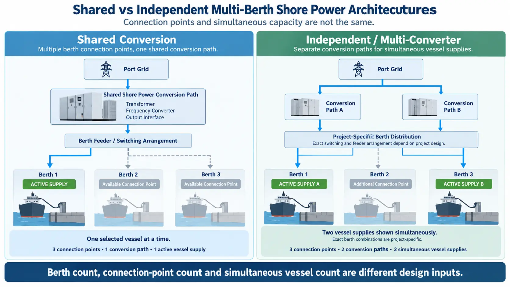
A terminal can have three berth connection points and only one shared conversion path. Another three-berth terminal may require two independent shore power systems because two vessels must be supplied simultaneously. A third terminal may use a movable shore power unit that is repositioned between berths.
These are all multi-berth systems, but they do not require the same electrical architecture.
That distinction should be made before converter capacity, transformer capacity, feeder arrangement, protection, metering and control logic are fixed.
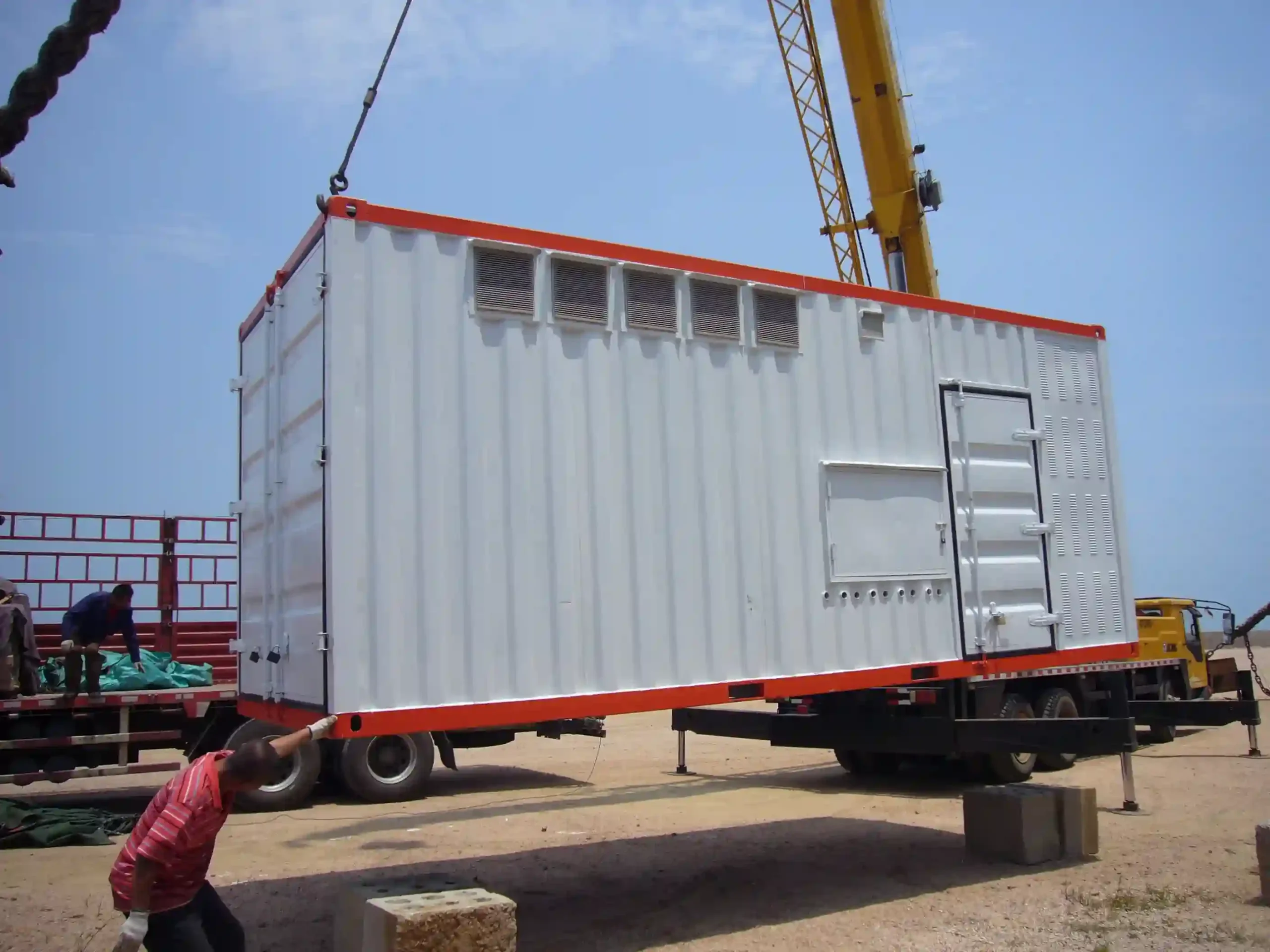
Start With the Berth Operating Matrix
A berth layout tells you where vessels can connect. It does not tell you how the electrical system must operate.
Before selecting equipment, define the operating combinations.
For each berth, confirm:
- vessel types and expected calls;
- required voltage and frequency;
- maximum electrical demand;
- large motors and starting methods;
- low-voltage or medium-voltage connection;
- connection-point location;
- cable route and distance;
- whether another berth may require shore power at the same time.
Then define which berth combinations must be available.
A three-berth terminal may allow only one active vessel at any time. Another may need two berths energized simultaneously. If the installed plant is intentionally smaller than the sum of all possible berth loads, those operating restrictions must be built into the system philosophy rather than left to operator memory.
The vessel, grid and load information needed before this stage is covered in our shore power selection and compatibility guide .
Choose the Architecture From the Operating Requirement
There is no single correct multi-berth architecture.
The electrical arrangement should follow what the terminal is expected to do.
Shared Conversion Path
A shared system can serve several physical berth connection points from one common conversion path when the operating plan does not require those berths to be energized simultaneously.
In one three-berth 630 kVA configuration, the electrical system included one 630 kVA frequency-conversion system with phase-shifting transformer, one 630 kVA dry-type isolation transformer, metering equipment, two high-voltage switchgear units, three low-voltage switchgear units and three berth-side connection boxes.
Three low-voltage outputs were provided to the berth front, but they were arranged to supply one vessel at a time across the three berth locations. The same system architecture included incoming and outgoing switchgear, frequency conversion, phase-shifting and isolation transformers, berth connection equipment, local and remote monitoring, communication and input/output energy metering.
The additional connection points increased where a vessel could connect. They did not multiply the installed conversion capacity.
Independent Conversion Paths
The requirement changes when two vessels must receive shore power at the same time.
Separate conversion paths may then be needed so that each active vessel has sufficient conversion capacity, transformation, distribution and control.
That decision affects more than the converters. The upstream grid, transformers, switchgear, berth feeders, protection, metering and auxiliary systems all need to support the simultaneous operating condition.
Our shore power system architecture and components page explains how these elements form the complete shore-to-ship electrical path.
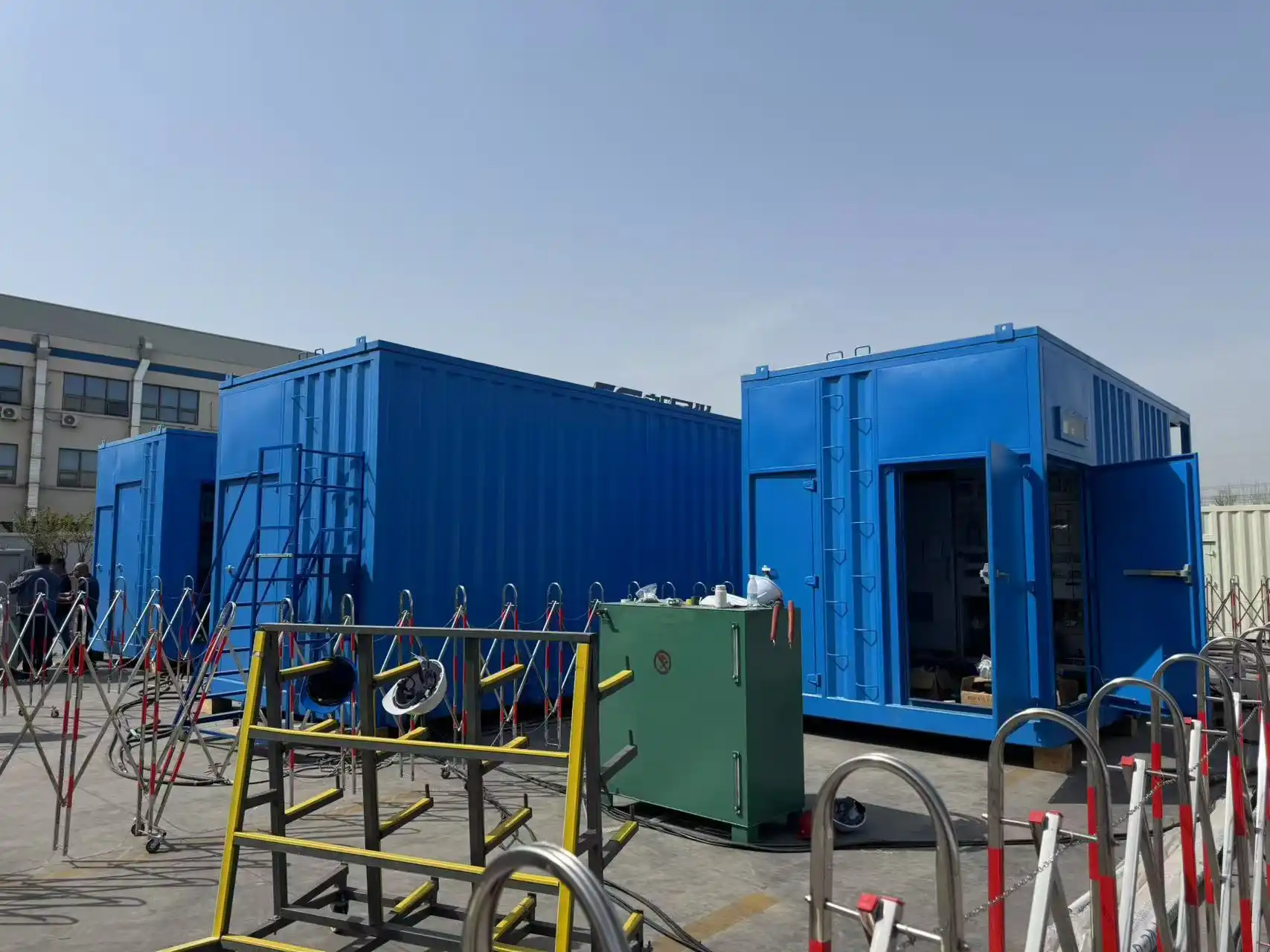
Movable Supply for More Than One Berth
A multi-berth terminal does not always need one large central plant or one fixed converter at every berth.
A 500 kVA movable configuration for two berths used incoming ring-main equipment, low-voltage outgoing switchgear, a 500 kVA isolation transformer, a motorized chassis, berth-side connection equipment and ventilation. The unit could be positioned near the selected berth and convert the available 6/6.6 kV supply to low-voltage 50 Hz or 60 Hz vessel power.
This type of arrangement can be useful where the vessel schedule, berth spacing and operating pattern do not justify duplicated fixed equipment.
What a Multi-Berth Power Path Actually Contains
A shore power system is more than:
A complete 630 kVA configuration included:
- high-voltage incoming and outgoing switchgear;
- phase-shifting transformer;
- frequency-conversion system;
- isolation transformer;
- low-voltage distribution;
- berth-side connection boxes;
- local and remote monitoring;
- protection and communication;
- energy metering;
- power cables.
For multi-berth design, each common component creates two questions:
How many berth connection points depend on it?
What happens to berth availability if that component is isolated for maintenance or fault?
A terminal can have enough installed kVA for normal operation but still lose access to several berth positions because those berths depend on one common transformer, converter or switchgear section.
Converter rating alone therefore does not describe the real availability of the system.
Size Capacity From Simultaneous Duty, Not Outlet Count
Do not calculate the required shore power capacity by multiplying the number of berth outlets by one assumed vessel rating.
Average energy consumption is also not enough.
The plant should be checked against the maximum credible simultaneous operating condition.
That review can include:
- continuous vessel demand;
- coincident demand from more than one vessel;
- large motor starting;
- step changes in load;
- transformer losses;
- converter losses;
- auxiliary loads;
- engineering margin.
A port with three connection points may need only one active 630 kVA conversion path if its operating rule allows one vessel at a time.
Another three-berth terminal may need two complete 5 MVA systems because two large vessels must be supported simultaneously.
Check Each Berth as a Complete Electrical Path
A shared source still needs a clearly defined electrical path to every berth where a vessel may connect.
For each berth path, review:
- switching;
- isolation;
- conductor size;
- feeder length;
- voltage drop;
- protection;
- fault duty;
- grounding and neutral arrangement;
- status indication;
- connection equipment.
The berth closest to the converter and the berth at the end of the longest feeder should not automatically be treated as electrically identical.
Cable distance, current, conductor arrangement and installation method affect voltage drop and fault conditions.
The Converter Changes the Short-Circuit Study
A converter-based shore power system cannot always be treated like a conventional transformer-and-cable distribution network.
In the 630 kVA system short-circuit calculation, the fault study was divided into two sections:
- the network before the frequency converter; and
- the converter output / vessel side.
The reason is that the frequency-conversion stage sits between the upstream network and the vessel load, so the fault path differs from a simple transformer-fed system.
For a multi-berth terminal, fault duty may need to be checked again when:
- several feeders share one conversion source;
- berth routes have different impedances;
- the output voltage level changes;
- a new transformer or switchgear section is added;
- the active berth path is changed.
Different Voltage and Frequency Requirements Can Change the Architecture
Different vessels may require different electrical conditions.
One berth may need 50 Hz low-voltage supply while another vessel requires 60 Hz. Larger vessels may require medium-voltage shore power instead of low voltage.
A shared conversion system can support different operating modes when those modes are selected separately and the equipment is designed for them.
The three-berth 630 kVA configuration included both 50 Hz and 60 Hz low-voltage supply modes.
The more important multi-berth question is whether different outputs must be supplied at the same time.
If two active vessels require different voltage or frequency conditions simultaneously, the terminal needs electrical paths capable of producing those outputs independently.
Depending on the project, that may mean:
- separate conversion paths;
- separate downstream transformers;
- separate distribution sections;
- or another purpose-designed arrangement.
Control, Metering and SCADA Need to Follow the Active Berth
A multi-berth shore power system is not complete if the operator cannot identify which berth and electrical path are active.
Operating information may include:
- breaker status;
- voltage;
- current;
- power;
- energy;
- alarms;
- transformer condition;
- equipment operating status.
One shore power monitoring configuration measured output voltage and current for energy calculation, transferred energy and billing data to the monitoring center over fiber Ethernet, and provided SCADA functions for fault queries, operating-data records, parameter settings, breaker status and transformer operating conditions.
For multi-berth operation, the control system has to associate the active berth with the correct electrical path.
If only one berth is permitted to operate from a shared conversion path, a second incompatible berth command should not create an unintended parallel demand.
If two vessel supplies are available simultaneously, each active path needs clear status visibility.
Metering Needs a Clear Boundary
The 630 kVA configuration included energy metering on both the input and output sides.
For a multi-berth terminal, another question then follows:
If electricity is settled separately by berth or vessel, the measurement boundary should match that billing arrangement.
A common upstream meter may be useful for total system energy, but it does not automatically provide individual vessel settlement data.
Three Berths With One 630 kVA Conversion System
A three-berth low-voltage design used one 630 kVA conversion system to serve three berth-side connection locations.
The electrical chain included the frequency-conversion system, phase-shifting transformer, dry-type isolation transformer, metering, high- and low-voltage switchgear and three berth-side connection boxes.
Three berth outputs were available, but the operating arrangement supplied one vessel at a time.
Three Berths With Two 5 MVA Shore Power Systems
A high-voltage shore power project used two systems rated at 5000 kVA each across three berths.
The two systems were designed to support two 200,000-ton-class vessels using shore power simultaneously. Each system connected to two output connection boxes, allowing vessel connection from different berth positions.
The electrical system converted a 10 kV / 50 Hz port supply to the required 6.6 kV vessel supply and supported 50 Hz and 60 Hz operating modes.
During vessel-connection testing, approximately 1500 kW of onboard generator load was transferred to shore power, with the control system completing the transfer in about 30 seconds before the generator was removed from the supply.
Two Different Architectures, One Design Principle
| Design Input | 630 kVA Configuration | 2 × 5 MVA Configuration |
|---|---|---|
| Berth locations | 3 | 3 |
| Conversion systems | 1 | 2 |
| Simultaneous vessel supply | 1 vessel | 2 vessels |
| Berth-side connection points | Multiple | Multiple |
| Vessel supply level | Low voltage | High voltage |
| Main architecture | Shared conversion | Simultaneous conversion paths |
The two systems serve different vessels and power levels.
Reliability Starts With the Failure You Need to Survive
“Redundant” is not a complete engineering requirement.
The project should define what failure must be tolerated.
- continued operation after one power module fails;
- continued berth availability after one complete converter is isolated;
- continued operation after one feeder fails;
- operation during transformer maintenance;
- availability of another berth while common switchgear is out of service.
The 630 kVA converter specification used modular IGBT power units and included detection and bypass/removal logic for a failed power unit under the stated control strategy.
That is redundancy at the power-module level.
It does not create a second complete converter, transformer, feeder or berth supply path.
A requirement written this way can be translated into the actual converter, transformer, switchgear and feeder architecture.
For procurement, commercial shore power systems should be evaluated by complete operating architecture, not converter kVA alone.
Common Multi-Berth Shore Power Design Errors
- Counting connection boxes as installed capacity. Three physical connection points do not mean three vessels can receive full converter output simultaneously.
- Sizing from average load. Average consumption does not show maximum coincident demand, motor starting or sudden load steps.
- Selecting the converter before defining the operating matrix. Equipment capacity can be correct on paper and still fail to match the real berth schedule.
- Ignoring the longest feeder. The most distant berth may require a different conductor size or voltage-drop review.
- Treating short-circuit analysis as a transformer-only problem. A frequency converter changes the electrical fault path between the grid and vessel.
- Leaving berth selection to operator memory. Restricted berth combinations should be enforced through the operating and control philosophy.
- Treating module redundancy as complete-system redundancy. A bypassable power module does not create another complete shore power path.
- Defining metering after the electrical architecture. Vessel-level settlement requires the measurement boundary to be agreed while the berth distribution is being designed.
Information Needed Before Configuring a Multi-Berth System
The engineering review should start with project data, not a preselected converter rating.
Berth and Vessel Data
- berth layout;
- number and location of connection points;
- expected vessel types;
- vessel calling pattern;
- number of vessels requiring simultaneous shore power;
- connection position at each berth.
Electrical Data
- vessel voltage;
- vessel frequency;
- maximum demand;
- largest motors;
- motor starting method;
- LV or MV vessel connection;
- port-grid voltage and frequency;
- available grid capacity;
- available short-circuit capacity.
Distribution Data
- cable route to each berth;
- approximate feeder distance;
- berth connection-box location;
- grounding and neutral requirements;
- existing switchgear and transformer interfaces.
Operating Requirements
- permitted berth combinations;
- berth priority if installed capacity is limited;
- maintenance philosophy;
- permitted outage duration;
- redundancy requirement.
Control and Commercial Requirements
- local operating requirement;
- remote SCADA requirement;
- required operating signals;
- energy-metering boundary;
- vessel or berth billing method;
- communication interface.
With these inputs, converter quantity, transformer capacity, berth distribution, fault duty, protection, metering and control can be reviewed as one system.
Frequently Asked Questions
Yes. One conversion path can serve several berth connection points when the distribution and operating sequence are designed for that arrangement. More connection points do not increase the available converter capacity.
No. It depends on how many vessels must be supplied simultaneously, their electrical requirements, the distribution architecture and the required availability.
Not necessarily. Each connection point needs a defined switching, isolation, protection and status path, but the feeder arrangement depends on the overall architecture.
Start with the maximum credible simultaneous vessel condition. Then check converter capacity, transformer capacity, grid capability, large motor starting, feeder losses and the required engineering margin.
Yes, if the conversion system and distribution architecture are designed for those operating modes. If different output conditions are needed simultaneously at different berths, independent electrical paths may be required.
Because it sits between the upstream network and the vessel-side load. The upstream and output-side fault conditions therefore need to be checked according to the actual converter-based architecture.
The control system should prevent an operating combination that exceeds the approved capacity or switching philosophy. Berth priority, permissive logic and operator response should be defined in the control design.
Not automatically. Module redundancy, converter redundancy, transformer redundancy and feeder redundancy address different failure conditions.
Discuss Your Multi-Berth Shore Power Project
Send the berth layout, vessel electrical data, simultaneous operating requirement, cable distances and available port-grid information.
We can review the conversion capacity, transformer configuration, berth distribution, protection, metering, control and redundancy requirements before the system configuration is fixed.
