
Phase-Shifting Transformer vs Isolation Transformer in Shore Power
A phase-shifting transformer and an isolation transformer can appear in the same shore power system, but they are not two versions of the same device.
They exist because a shore power project may have to solve different electrical compatibility problems at different points in the power path.
On the converter side, the input transformer may have to provide the voltage levels and phase relationships required by the rectifier topology.
On the vessel side, an isolation transformer may have to provide the required connection voltage, electrical separation and neutral arrangement.
Between them, a frequency converter may be required when the shore and vessel frequencies do not match.
If these functions are treated as interchangeable, the result is not simply an inefficient transformer selection. The consequences can include poor harmonic performance, incorrect vessel voltage or frequency, protection and grounding incompatibility, excessive voltage drop, and problems during shore-to-ship integration.
Phase-Shifting Transformer vs Isolation Transformer at a Glance
| Design Question | Phase-Shifting Transformer | Isolation Transformer |
|---|---|---|
| Main role | Supports converter input architecture | Supports vessel-side electrical interface |
| Main design relationship | Rectifier inputs, secondary phase relationships and converter topology | Vessel voltage, neutral, insulation and protection |
| Position in the 630 kVA converter-based example | Before the power-electronic conversion stage | After the frequency converter |
| Harmonic relationship | Can support harmonic mitigation through phase-shifted rectifier supplies | Not the primary converter-input harmonic-control device |
| Frequency conversion | No | No |
| Voltage transformation | May be part of converter-input design | May establish the final vessel connection voltage |
| Automatically interchangeable? | No | No |
The difference is defined by system function and position, not by transformer appearance alone.
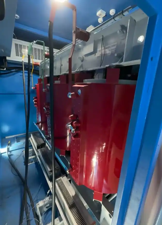
Why This Transformer Question Exists in Shore Power
A vessel does not automatically present the same electrical requirements as the port grid.
Three electrical layers have to work together:
Shore Source
Available voltage, frequency and fault level.
Power-Conversion Stage
Rectifier topology, DC link, inverter and power-quality strategy.
Vessel Interface
Required voltage, frequency, neutral arrangement, grounding and protection.
The transformer arrangement is a consequence of those interfaces.
This system-level view is also reflected in the current international framework for low-voltage shore connection. IEC/IEEE 80005-3:2025 applies to three-phase low-voltage shore connection systems rated 250 A and above, with nominal voltages from 400 V to 1,000 V AC, for ships requiring up to 1 MVA while at berth. Its scope includes transformers and reactors, frequency converters, shore-to-ship interfaces, protection, control, monitoring and interlocking.
Before a shore connection is accepted as compatible, the shore-side and vessel-side electrical systems also have to be reviewed together. IMO guidance for onshore power supply addresses compatibility or technical analysis and first-connection integration testing rather than treating an individual transformer rating as proof that the complete interface is suitable.
This is why transformer selection should begin with the electrical problem, not with a standard equipment list.
What the Phase-Shifting Transformer Does on the Converter Side
A frequency converter can contain multiple rectifier inputs or modular power-electronic stages.
Those rectifier circuits do not only require a nominal voltage. In multipulse arrangements, they may also require defined phase displacement between their AC supplies.
A phase-shifting transformer can create those secondary phase relationships while also adapting the input voltage to the converter.
The transformer and converter are therefore electrically linked.
The required design can depend on:
- rectifier topology,
- number and arrangement of rectifier inputs,
- secondary voltage,
- phase displacement,
- transformer impedance,
- harmonic requirements,
- and converter control architecture.
A transformer that provides the correct kVA and nominal voltage can still be unsuitable if its winding arrangement does not match the converter topology.
In multipulse rectification , phase-shifting transformer connections can be used to establish the required phase displacement between rectifier units. This is one reason the phase-shifting transformer belongs to the converter-side design problem, rather than being treated as a generic upstream transformer.
For the deeper harmonic mechanism and power-quality measurement boundaries, see our shore power harmonics and power quality article.
What Happens If the Converter-Side Harmonic Problem Is Not Controlled?
Poor input harmonic performance is not only a THD issue.
Harmonic current can increase losses and heating in transformers, cables, motors and other equipment. It can also contribute to unwanted protection operation, measurement problems, unreliable operation and unnecessary interruptions.
For a shore power converter, this is why the input transformer and harmonic-control strategy have to be considered together.
- higher electrical and thermal loading,
- additional transformer and cable heating,
- unwanted protection operation,
- measurement or control problems,
- and reduced operating reliability.
Where a multipulse topology depends on phase-shifted rectifier supplies, the transformer phase relationships therefore become part of the harmonic-control strategy.
Phase Shifting Is Not the Only Possible Harmonic Solution
Phase shifting is not a universal requirement for every shore power converter.
Other power-electronic topologies can use different input-side strategies.
In broader drive applications, active-front-end low-harmonic designs are one example of an approach that can avoid multipulse arrangements and the special transformer arrangements associated with them.
The appropriate solution for a shore power converter still depends on its own topology, harmonic requirements and project conditions.
What the Isolation Transformer Does on the Vessel Side
The output isolation transformer solves a different problem.
In a converter-based low-voltage shore power arrangement, it can provide electrical separation between the conversion equipment and the vessel-side network.
It can also establish the voltage required at the vessel connection.
Its winding arrangement may provide the neutral point required by the project and has to be coordinated with:
- vessel distribution,
- neutral treatment,
- grounding,
- protection,
- and transfer conditions.
If the shore grid supplies 50 Hz and the vessel requires 60 Hz, the frequency converter has to create the 60 Hz output.
A transformer can change voltage and phase relationship. It cannot convert a 50 Hz waveform into a 60 Hz waveform.
This is why the isolation transformer belongs to the vessel-interface problem, while the phase-shifting transformer belongs to the converter-input problem.
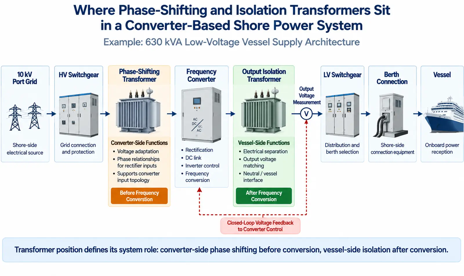
A 630 kVA Power Path Shows Why Both Transformer Functions Can Be Required
In one 630 kVA low-voltage shore power arrangement, both transformer functions appear in the same power path.
The system includes:
- a 10 kV shore supply,
- high-voltage switchgear,
- a 630 kVA frequency-conversion system containing a phase-shifting transformer,
- a separate 630 kVA dry-type isolation transformer,
- low-voltage feeder switchgear,
- berth-side connection equipment,
- monitoring,
- protection,
- communication,
- and input/output metering.
The two transformers are not duplicate equipment.
The phase-shifting transformer supports the converter input.
The frequency converter performs the active power conversion and creates the required output frequency.
The output isolation transformer then becomes part of the vessel-side electrical interface.
This architecture shows why two transformers with similar kVA ratings can still have fundamentally different design duties.
The Output-Voltage Feedback Point Shows Why Transformer Position Matters
In the same 630 kVA arrangement, output-voltage closed-loop measurement is taken on the output side of the isolation transformer.
That measurement point matters.
Because the feedback is taken after the isolation transformer, the transformer lies inside the voltage-control boundary.
The converter is therefore regulating a voltage measured after the transformer rather than only at its own power-electronic output terminals.
This creates a direct engineering relationship between:
- converter control,
- transformer ratio,
- transformer impedance,
- and the voltage delivered on the output side.
The output transformer is therefore not an accessory that can be added after the converter has already been fully defined.
Its characteristics have to be coordinated with the controlled power path.
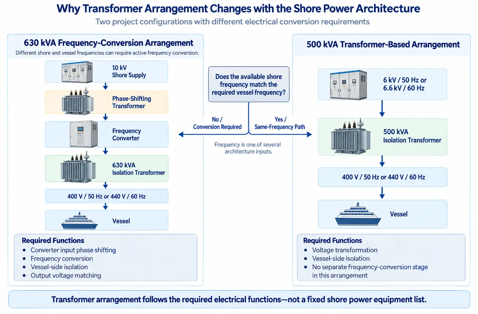
A 500 kVA Arrangement Shows Why the Same Transformer Chain Is Not Always Needed
A separate low-voltage shore power arrangement uses a different architecture.
The 500 kVA mobile system accepts either:
- 6 kV / 50 Hz, or
- 6.6 kV / 60 Hz,
and supplies:
- 400 V / 50 Hz, or
- 440 V / 60 Hz,
through a 500 kVA isolation transformer, low-voltage switchgear and berth-side connection equipment.
The same converter-side phase-shifting stage used in the 630 kVA frequency-conversion arrangement is not part of this equipment chain.
The reason is the electrical task.
When the available shore frequency already matches the required vessel frequency, a project may not require the same active frequency-conversion stage.
The architecture can therefore change from:
to a simpler transformer-based path where the main requirements are:
Voltage Transformation → Vessel-Side Isolation
This does not make one architecture more advanced than the other.
It means the required equipment follows the electrical functions that have to be performed.
Class rules illustrate the same system-level principle. In Bureau Veritas' 2025 OPS rules , the typical arrangement includes a static or rotating converter where applicable—for example when shore and vessel frequencies differ—and an onboard transformer where applicable to the vessel-side network.
This is a class-specific arrangement example, not a universal requirement for every shore power system.
Transformer Selection Is a Compatibility Problem, Not a Nameplate Problem
A transformer can have the correct kVA and voltage ratio and still be unsuitable for the final shore-to-vessel interface.
The wider compatibility review has to consider:
- shore voltage and frequency,
- vessel voltage and frequency,
- phase sequence,
- converter topology,
- vector relationship,
- neutral and grounding,
- protection,
- interlocking,
- and operating method.
Before the first connection, the shore and vessel electrical systems have to be assessed as one operating interface.
That review goes beyond transformer kVA. It includes protection, interlocking, controls, phase sequence, equipotential-bond monitoring and the ability of the shore and vessel systems to operate correctly together.
Why One Transformer Cannot Automatically Replace the Other
Both transformer types may provide isolation between windings.
That does not make them interchangeable.
A phase-shifting transformer may have to satisfy:
- converter input voltage,
- multiple rectifier supplies,
- phase displacement,
- converter topology,
- and harmonic strategy.
An output isolation transformer may have to satisfy:
- vessel connection voltage,
- insulation requirements,
- neutral arrangement,
- grounding philosophy,
- protection coordination,
- and output-voltage behavior.
Replacing a phase-shifting transformer with a conventional two-winding transformer can remove phase relationships required by the rectifier topology.
Using a converter-input transformer as the final vessel-interface transformer can create a different mismatch: its winding arrangement may suit the converter but not the vessel network.
For the complete relationship between transformers, frequency converters, switchgear and berth interfaces, see our shore power system architecture and components page.
Transformer Position Changes the Short-Circuit Study Boundary
Transformer position also changes the fault-study boundary.
In the 630 kVA converter-based system, the short-circuit analysis is divided into the electrical network before the converter and the converter output side toward the vessel.
The distinction is necessary because the frequency converter changes the electrical behavior of the source.
The upstream network contains the shore grid and upstream transformer path.
The downstream side contains a controlled power-electronic source together with the output transformer and vessel-side equipment.
grid → transformer → cable → load
The converter boundary has to be identified before fault-current assumptions are applied.
This is another reason transformer position matters: the two transformers do not participate in the same electrical network in the same way.
Transformer Impedance Creates a Design Trade-Off
Transformer impedance affects both fault current and normal voltage performance.
Large vessel motors introduce another constraint.
Motor starting can cause a temporary voltage dip, so transformer impedance has to be reviewed together with:
- available shore power capacity,
- converter transient response,
- motor starting current,
- starting method,
- vessel load profile,
- and allowable voltage dip.
There is therefore no useful universal impedance value that should simply be copied from another shore power installation.
The final value has to be coordinated with the actual system study.
Vector Group and Neutral Arrangement Are System Decisions
Vector group is another example of why transformer selection cannot be based on kVA alone.
In one 630 kVA output-isolation-transformer design, the specified connection is Dyn11, with 440 V / 400 V secondary requirements.
That is one project solution.
It is not a universal shore power requirement.
The vector group has to be reviewed together with:
- the shore single-line diagram,
- the vessel single-line diagram,
- required phase relationship,
- neutral arrangement,
- earth-fault protection,
- transfer method,
- and synchronization requirements where applicable.
Copying a vector group from another installation without checking these interfaces can produce a transformer that is electrically valid on its own but incorrect for the new shore-to-vessel system.
What the Transformer Arrangement Does Not Solve by Itself
A correct transformer arrangement is important, but it does not solve every shore power interface problem.
This distinction prevents a common procurement error: treating a list of individually correct equipment ratings as proof that the complete shore power system will operate correctly with the vessel.
Thermal Monitoring Is Part of Transformer Engineering
Transformer loading is also a thermal issue.
In one 630 kVA dry-type transformer design, temperature sensors were installed in the low-voltage windings, with:
- three-phase winding-temperature indication,
- high-temperature alarm,
- overtemperature trip output,
- automatic cooling-fan control,
- temperature-sensor fault alarm,
- and cooling-fan fault alarm.
These functions matter because excessive winding temperature can affect insulation life and operating availability.
In a containerized shore power installation, transformer losses also contribute to the HVAC heat load together with the converter and switchgear.
The transformer therefore has to be coordinated with:
- enclosure ventilation,
- ambient temperature,
- heat rejection,
- monitoring,
- alarms,
- and maintenance access.
For the wider thermal design, see our shore power system cooling and HVAC design article.
How the Transformer Arrangement Should Be Verified
Transformer selection should not end when the supplier submits a datasheet.
Verification should follow the electrical role assigned to each transformer.
For the converter-input side, review:
- transformer ratio,
- winding arrangement,
- phase displacement,
- converter input topology,
- harmonic requirements,
- transformer impedance,
- and converter compatibility.
For the vessel-side transformer, review:
- output voltage,
- vector group,
- neutral point,
- insulation requirements,
- grounding philosophy,
- protection settings,
- and output-voltage regulation.
At system level, the shore and vessel installations also have to be checked together.
First-connection verification can include:
- protection-device tests,
- interlocking tests,
- control-function tests,
- equipotential-bond monitoring,
- phase-sequence checks,
- and shore-to-ship integration testing.
Component
Does each transformer meet its electrical specification?
Subsystem
Does it operate correctly with the converter, switchgear and protection?
Shore-to-Vessel System
Does the complete interface operate correctly with the actual vessel?
What Must Be Confirmed Before the Transformer Arrangement Is Frozen
A transformer arrangement should remain open until the project interfaces are sufficiently defined.
Shore-Side Electrical Data
- Port-grid voltage
- Port-grid frequency
- Available short-circuit capacity
- Existing transformer arrangement
- Available feeder capacity
Converter Data
- Whether frequency conversion is required
- Converter topology
- Converter input voltage
- Rectifier or power-cell input arrangement
- Harmonic requirements and measurement boundary
- Output voltage and frequency range
Vessel-Side Data
- Vessel connection voltage
- Vessel frequency
- Required shore power capacity
- Vessel single-line diagram
- Neutral arrangement
- Grounding method
- Largest motor
- Motor-starting method
- Operating load profile
Protection and Operating Data
- Short-circuit study requirements
- Earth-fault protection philosophy
- Synchronization or transfer method
- Allowable voltage drop
- Output switchgear rating
- Protective-earth and pilot arrangement
Installation Data
- Transformer location
- Enclosure type
- Ambient conditions
- Ventilation
- Cooling concept
- Maintenance access
If several of these inputs are unknown, the transformer quantity, winding arrangement or final interface should not be frozen.
Selecting a transformer first and forcing the rest of the shore power system to fit around it reverses the correct engineering sequence.
Frequently Asked Questions
Does a phase-shifting transformer change frequency?
No. It provides voltage transformation and phase relationships according to its winding design. Frequency conversion is performed by the power-electronic converter.
Why is phase shifting used with some shore power converters?
It can provide different phase relationships to multiple rectifier inputs, allowing a multipulse converter topology to reduce selected characteristic input harmonics.
Does every shore power converter need a phase-shifting transformer?
No. The requirement depends on converter topology. Other low-harmonic converter architectures can use different input-side solutions.
Why can a 630 kVA system use both transformers?
Because the two transformers solve different electrical problems. The phase-shifting transformer supports the converter input. The output isolation transformer supports the vessel-side voltage, isolation and neutral interface.
Is an isolation transformer always installed after the converter?
No. That position is used in the 630 kVA converter-based arrangement discussed here, but transformer location depends on the complete shore power architecture.
Can one transformer perform both functions?
Potentially, but not automatically. Its winding arrangement, phase relationships, voltage levels, converter interfaces, neutral requirements and vessel-side duties all have to satisfy both roles.
Is Dyn11 required for shore power?
No. Dyn11 is one possible project configuration. Vector group selection depends on the actual vessel network, neutral arrangement, grounding, protection and transfer requirements.
Why does the output-voltage feedback point matter?
Because it defines where the converter measures the controlled output voltage. When feedback is taken after the isolation transformer, that transformer lies inside the voltage-control boundary.
Why does transformer position affect short-circuit calculations?
Because the frequency converter separates the upstream shore network from a controlled power-electronic output domain. The two sides do not behave as one conventional transformer-only network.
Can transformer kVA and voltage ratio alone confirm shore-to-vessel compatibility?
No. Voltage, frequency, phase sequence, vector relationship, neutral, grounding, protection, converter behavior and system integration also have to be confirmed.
Technical References
- IEC/IEEE 80005-3:2025, Edition 1.0 — Utility Connections in Port — Part 3: Low-Voltage Shore Connection Systems — General Requirements. Current LVSC system scope, including transformers, converters, interfaces, protection, control and monitoring.
- IMO MSC.1/Circ.1675, 27 June 2023 — Interim Guidelines on Safe Operation of Onshore Power Supply Service in Port for Ships Engaged on International Voyages. Operational guidance for OPS compatibility, safe operation and first-connection testing. This circular predates the final publication of IEC/IEEE 80005-3:2025.
- Schneider Electric, Electrical Distribution Fundamentals Design Guide, Version 2.0, 20 March 2025 — multipulse rectification, harmonic behavior and phase-shifting transformer principles.
- ABB, Guide to Harmonics / Harmonics Technical Resources — harmonic mechanisms, equipment heating, protection operation and alternative harmonic-mitigation approaches.
- Bureau Veritas, Rules for the Classification of Steel Ships, Part F, Chapter 14, Section 5, July 2025 — class-specific OPS arrangement illustrating converter and onboard-transformer applicability according to interface conditions.
Review Your Shore Power Transformer Arrangement
If you are deciding whether a project requires a phase-shifting transformer, an output isolation transformer, both functions, or a different architecture, start with the complete shore-to-vessel power path.
Send:
- shore and vessel single-line diagrams,
- grid voltage and frequency,
- vessel voltage and frequency,
- required shore power capacity,
- converter topology,
- load list,
- largest motor and starting method,
- neutral and grounding requirements,
- harmonic requirements,
- and protection philosophy.
We can review where phase shifting, frequency conversion, voltage transformation and electrical isolation belong in the system—and what still needs to be verified before the transformer arrangement is frozen.
Send Your Project Requirements