
Shore Power Cable Management System Selection Guide
A shore power cable management system should be selected from the complete ship-to-shore operating interface—not from voltage, current or converter capacity alone.
A berthed ship is not a perfectly fixed electrical load. Its shore-power connection point can move because of tide, freeboard, cargo loading, ballast condition and small changes in mooring position.
At the same time, the flexible cable has its own mechanical limits. Cable mass, minimum bending radius, pulling force, connector loading and available cable travel can influence the cable-management architecture as much as the electrical rating.
Why Cable Management Becomes a System-Level Engineering Problem
The flexible connection has to remain mechanically controlled while the vessel and berth move relative to each other.
Too little cable travel can transfer load into the cable, connector, termination or reel. Too much uncontrolled slack can place the cable in vehicle routes, cargo areas, around sharp structures or close to the quay edge.
The cable-management system therefore performs more than cable storage. It manages the transition between a relatively fixed shore installation and a vessel whose connection point changes during the port stay.
Start With the Ship-to-Shore Interface
Before choosing a reel, boom or other handling mechanism, establish where the flexible connection begins and ends.
- Is the cable stored on the vessel or on shore?
- Where is the vessel shore-power inlet?
- Where is the berth connection point?
- Who deploys and retrieves the cable?
- Who maintains the flexible cable and connector?
- Does the vessel already have compatible cable-management equipment?
- Does the berth serve one ship type or a mixed vessel population?
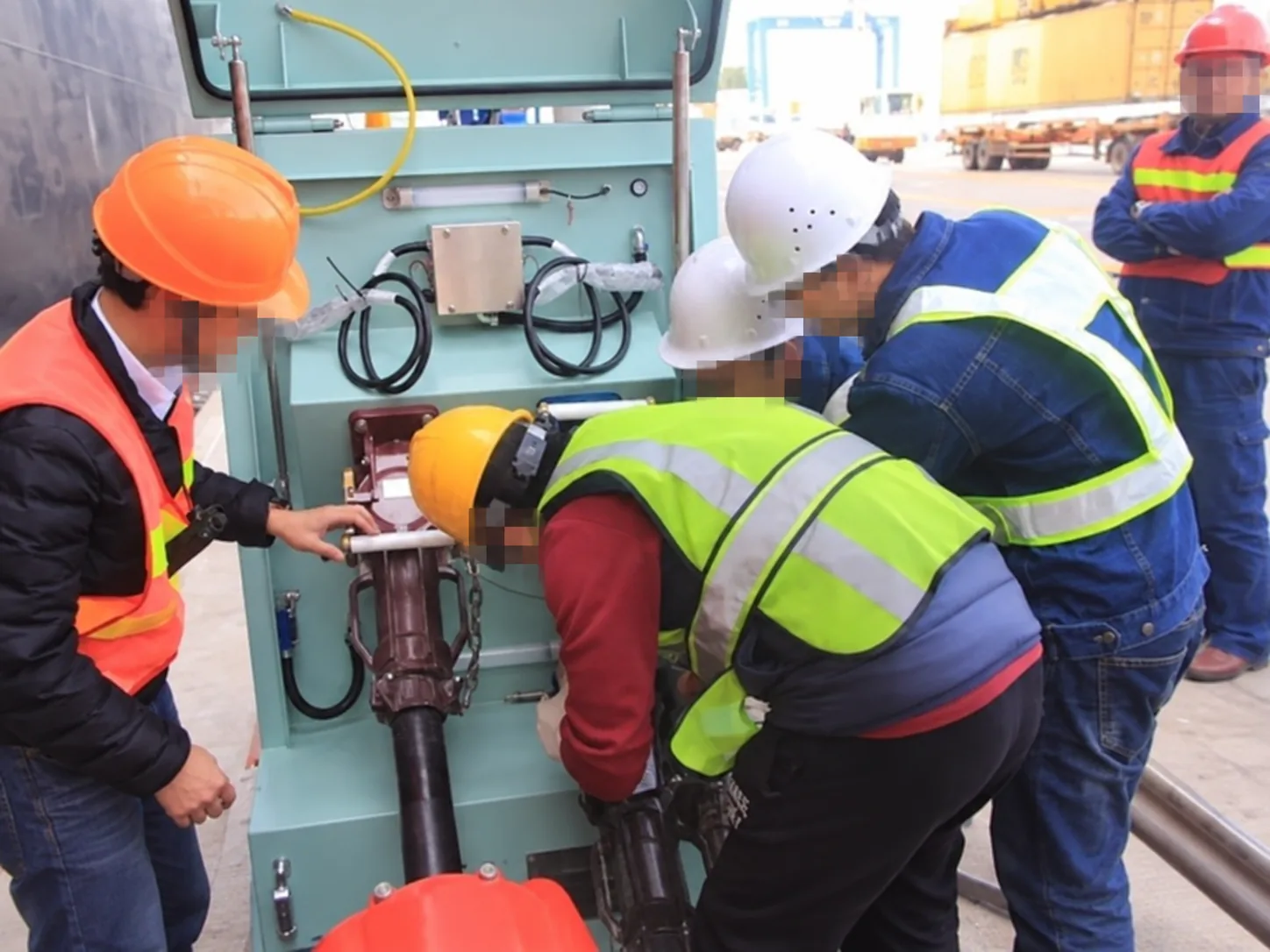
In one shore-power project configuration, the shore-side connection equipment included berth connection boxes while the vessel side used its own cable reel. The engineering boundary therefore extended beyond the socket: the berth also needed a practical receiving position and a clear route for cable deployment.
The operating environment can also determine where the cable-management equipment belongs. Container-terminal operations, for example, may favour an onboard arrangement where shore-side cable machinery would interfere with cargo movements.
For the electrical equipment behind the connection point, see our shore power system architecture and components .
Define the Full Vessel Movement Envelope
Cable-management equipment should not be selected from the normal vessel position alone. The relevant question is where the vessel inlet can be at every credible operating condition.
Horizontal Movement
- Mooring-position tolerance
- Different vessel lengths
- Different inlet locations
- Berth assignment
Vertical Movement
- Tidal range
- Freeboard
- Draft variation
- Cargo loading and unloading
Why the Limiting Position Matters
A vessel may present a very different cable geometry at high tide and light draft than at low tide after loading. The most demanding condition can combine both vertical and horizontal movement.
The review should therefore establish:
- minimum reach;
- maximum reach;
- minimum vertical offset;
- maximum vertical offset;
- the cable path at each limiting position.
Real project operating procedures follow the same principle. Before connection, vessel-side cable recovery equipment was checked and the vessel position was confirmed against the shore connection location. The exact allowable distance is project-specific; the transferable lesson is that connection geometry has to be verified before cable deployment.
How Cable Data Changes the Cable-Management Design
The cable should not be treated as an accessory selected after the reel. Its mechanical characteristics can change the entire CMS architecture.
Cable Outside Diameter
Cable diameter affects reel storage capacity, drum geometry, guide dimensions, roller arrangement and connector handling.
A drum may appear large enough to store the required cable length while still being unsuitable for the actual bending geometry.
Cable Mass per Metre
Cable mass affects payout and retrieval force, suspended load, drive requirement, supporting structure and manual-handling feasibility.
Over a long moving length, even a modest increase in mass per metre can create a substantial increase in total moving load.
Minimum Bending Radius
The selected cable manufacturer's minimum bending radius can directly determine:
- reel drum diameter;
- guide roller size;
- change-of-direction points;
- storage geometry;
- routing around berth structures.
A reel can have sufficient storage volume and still be mechanically unsuitable if the cable is bent too tightly during storage or payout.
Pulling and Tensile Limits
The correct response to increased resistance is not automatically more motor torque.
Excessive pulling force may indicate insufficient cable allowance, a trapped cable, poor routing, vessel movement or connector restraint. The cable-management system needs to stay within the mechanical limits of the cable and its terminations.
Torsional Behaviour
Repeated payout and retrieval can also introduce twist. Where torsion is relevant to the selected cable construction or routing arrangement, the cable manufacturer's limit should form part of the design review.
Compare the Main Cable-Management Arrangements
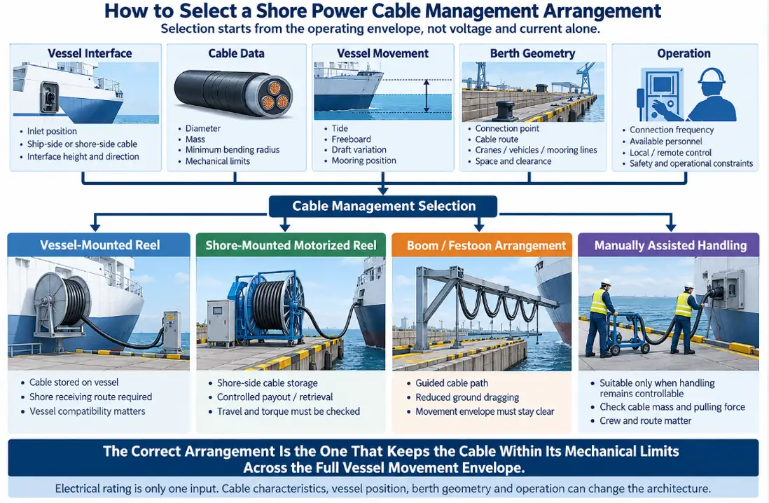
Vessel-Mounted Cable Reel
A vessel-mounted reel stores and deploys the flexible cable from the ship. This can reduce the amount of shore-side cable-handling machinery.
The berth still needs a compatible connection point, enough receiving space, a clear pulling route and an agreed operating method.
The main dependency is vessel compatibility. A mixed-fleet berth should not assume that every vessel carries equivalent cable-management equipment.
Shore-Mounted Motorized Reel
A shore-mounted reel keeps cable storage and payout equipment on the berth. This can reduce dependency on vessel-side cable machinery and give the port more direct control over cable handling.
The design review can include:
- stored cable length;
- drum diameter and width;
- guide geometry;
- payout and retrieval distance;
- movement speed;
- torque or tension management;
- emergency stopping;
- connector parking;
- maintenance access.
Boom, Jib or Festoon Arrangement
A guided overhead arrangement can keep the cable away from the working surface and reduce dragging or vehicle exposure.
It also introduces structural and movement constraints. The design must consider the cable load, wind, movement envelope, quay cranes, loading equipment, mooring lines, parking position and storm securing.
Movable Shore-Side Connection Point
Another option is to move the shore connection interface closer to the vessel rather than increasing flexible cable length indefinitely.
This can be useful on long berths or where vessel alignment varies significantly. The engineering burden then shifts toward quay travel, positioning, mechanical guidance and integration with berth operations.
Manually Assisted Cable Handling
Manual assistance can be appropriate when the physical cable assembly remains controllable.
The decision should be based on actual cable mass, connector mass, pulling force, deployment distance, route condition, connection frequency, crew availability and any lifting or trolley assistance.
Engineering Selection Matrix
The following matrix is a decision framework, not a ranking. Each architecture moves the engineering burden to a different place.
| Engineering Question | Vessel-Mounted Reel | Shore-Mounted Reel | Boom / Festoon | Movable Shore Interface | Manual-Assisted |
|---|---|---|---|---|---|
| Who stores the flexible cable? | Vessel | Shore | Shore | Depends on architecture | Vessel or shore |
| Dependence on vessel CMS | High | Low | Low | Medium | Depends |
| Heavy cable handling | Depends on vessel equipment | Strong when engineered correctly | Strong when engineered correctly | Depends on cable ownership | Limited by handling method |
| Ground cable exposure | Depends on route | Can exist | Usually reduced | Can be reduced | Often greater |
| Variable vessel position | Vessel system must cover it | Reel travel must cover it | Boom envelope must cover it | Interface can move toward vessel | Limited |
| Shore structural equipment | Low | Medium | Higher | Medium–High | Low |
| Automation potential | Vessel dependent | High | High | High | Low |
| Main design concern | Vessel compatibility | Reel geometry and force | Structure and movement envelope | Quay travel and alignment | Human handling burden |
Cable Management Is Also an Electrical Interface
The cable-management mechanism is mechanical, but the flexible connection itself is part of the electrical protection and control interface.
Depending on the system, the connection can include:
- phase conductors;
- protective earth;
- equipotential bonding;
- pilot conductors;
- communication links;
- connector-position status;
- emergency-stop functions.

Mechanically connected does not necessarily mean electrically ready. Protective continuity, connector locking, pilot status, cable-management condition and project-defined permissive logic may all need to be valid before energization.
For the detailed electrical interface behind the connector, see our shore power connection box specification .
Controlled Slack Is a Designed Operating Condition
Some cable allowance is required because the vessel moves.
Uncontrolled slack is not desirable.
In one project connection procedure, shore personnel pulled the vessel cable toward the berth connection box and deliberately left suitable cable allowance before securing the connection and carrying out the safety-circuit test.
The engineering target is therefore enough cable freedom for vessel movement, but not enough uncontrolled cable to create another operational hazard.
Cable allowance should be coordinated with:
- quay edge geometry;
- vehicle routes;
- crane movement;
- cargo equipment;
- mooring lines;
- sharp structures;
- water exposure.
For the wider connection and energization sequence, see our shore power connection procedure .
Define CMS Signals and Control Authority
A motorized CMS needs more than a start and stop command.
Depending on the equipment and control philosophy, useful operating information can include:
- payout active;
- retrieval active;
- motion status;
- drum or cable position;
- local mode;
- remote mode;
- overload;
- excessive torque;
- fault;
- emergency stop;
- parking position;
- connector position.
In one monitored shore-power configuration, the cable reel included payout/retrieval status and alarms for fault, overload and excessive torque. These are project examples rather than a universal I/O list, but they show why CMS state can matter to the wider shore-power operating sequence.
Typical CMS Cause–Effect Logic
The final cause–effect matrix is project-specific. The table below shows the type of relationship that should be reviewed.
| Condition | Mechanical Response | Wider System Consideration |
|---|---|---|
| Reel overload | Stop or inhibit motion | Inspect cable route and obstruction |
| Excessive torque | Stop or limit continued pulling | Prevent mechanical loading of cable and connector |
| Emergency stop | Stop cable-management motion | Electrical response follows approved interlock philosophy |
| Connector not ready | No movement or energization as defined | Verify plug, PE and pilot conditions |
| Communication unavailable | Restrict remote authority where required | Maintain defined local safe operation |
| Travel limit reached | Stop further motion | Prevent over-travel |
Repeated Cable Movement Is a Reliability Issue
Shore-power cable management affects reliability as well as operator convenience.
High-voltage connection cables can experience repeated bending and pulling during payout and recovery. Internal technical experience also identifies repeated reel operation and cable stress as a mechanism that can contribute to insulation or ground-fault problems over time.
The better design question is therefore not simply:
It is: “Can the cable follow this path repeatedly without accumulating unacceptable mechanical stress?”
Repeated Bending
Every payout and retrieval cycle bends the cable. Poor reel or guide geometry can concentrate repeated bending in the same location.
Excessive Pulling
If the cable becomes trapped or the vessel moves beyond the available travel, drive force can be transferred to the cable termination or connector.
Abrasion
Dragging across concrete, steel edges or unprotected ground can damage the outer jacket and reduce the mechanical and environmental protection of the cable.
Connector Strain
A heavy suspended cable can impose continuous mechanical load on the plug unless suitable cable support and strain relief are provided.
Slip-Ring and Contact Wear
Where slip rings are used, repeated electrical and mechanical operation creates another maintenance point. Plugs, sockets and slip rings should be included in the inspection strategy for ageing, corrosion and contact condition.
What Real Shore-Power Operation Tells Us
1. Cable Ownership Changes the Interface
In one project, berth connection boxes operated together with a vessel-side cable reel.
Engineering meaning: the port may not need to store and deploy the flexible cable, but the berth still has to be designed around the vessel's cable operation.
2. Cable Recovery Equipment Is Part of Connection Readiness
Project procedures required vessel-side high-voltage cable recovery equipment to be in normal operating condition before connection.
Engineering meaning: the CMS is part of operational readiness, not auxiliary machinery that can be ignored until after the electrical system is ready.
3. Cable Allowance Is Deliberate
During deployment, controlled cable allowance was left before the connection was tested.
Engineering meaning: vessel movement should be accommodated before energization rather than corrected after the cable becomes taut.
4. Mechanical State Can Be Monitored
Reel payout/retrieval status and alarms for overload or excessive torque were included in one monitored configuration.
Engineering meaning: cable behaviour can be important enough to become part of the wider shore-power monitoring model.
Verify the CMS Before Final Selection
Geometry Verification
- Vessel inlet coordinates
- Maximum horizontal reach
- Minimum horizontal reach
- Maximum vertical travel
- Limiting tide condition
- Limiting draft condition
- Berth offset
- Cable route and clearance
Cable Verification
- Outside diameter
- Mass per metre
- Minimum bending radius
- Tensile or pulling limit
- Torsional limit where relevant
- Connector weight
- Termination details
Mechanical Verification
- Drum diameter and width
- Cable guide geometry
- Payout direction
- Support and strain relief
- Drive and torque requirement
- Travel limits
- Parking position
- Emergency stopping
- Maintenance access
Interface Verification
- Plug compatibility
- Protective-earth path
- Pilot circuit
- Plug locking
- Connector position
- Communication interface
- Emergency-stop path
- Energization permissive
CMS FAT and Commissioning Acceptance Checklist
Mechanical Functions
- Full payout
- Full retrieval
- Minimum travel position
- Maximum travel position
- Cable-guide operation
- Connector parking
- Cable support
Motion Protection
- Emergency stop
- Overload response
- Excessive-torque response where provided
- Travel-limit response
- Drive fault
Control
- Local control
- Remote control where provided
- Local/remote authority
- Motion feedback
- Alarm indication
- Reset logic
Electrical Interface
- Connector-position indication
- PE continuity
- Pilot state
- Permissive state
- Emergency-stop coordination
- Communication-loss response
Where practical, commissioning should also verify the limiting vessel positions, maximum required reach, minimum-slack condition and safe cable recovery after a trip.
Maintenance Should Influence Architecture Selection
A cable-management arrangement can work well at commissioning and still create poor lifecycle availability if critical components are difficult to inspect or replace.
Maintenance planning should consider:
- cable jacket condition;
- abrasion and deformation;
- strain relief;
- plug contacts;
- locking parts;
- socket condition;
- cable guides and rollers;
- reel bearings;
- drive mechanism;
- slip rings where fitted;
- PE continuity;
- pilot wiring;
- seals and corrosion condition.
Connection cycles can matter as much as elapsed time. Frequently used berths may need condition-based inspection rather than a maintenance plan based only on calendar intervals.
Common Cable-Management Selection Errors
Selecting from voltage and current alone. Electrical rating does not define cable mass, movement, bending geometry or berth conflict.
Using the average vessel as the design vessel. The limiting vessel and tide/draft condition should drive the movement-envelope check.
Selecting the reel before the cable is finalized. A change in cable OD, mass or bending radius can invalidate the reel and guide geometry.
Ignoring terminal operations. Cranes, vehicles, container handling and mooring operations can make an electrically convenient cable route impractical.
Treating the CMS as independent machinery. Reel motion, connector state, pilot status and electrical isolation can interact.
Forgetting recovery after a trip. Isolation, connector release and cable recovery should be defined before commissioning.
Information Required Before Selecting a Shore Power Cable Management System
Berth
- Berth layout
- Quay edge geometry
- Connection-box locations
- Cranes and vehicle routes
- Mooring equipment
- Restricted areas
Vessel
- Intended vessel types
- Shore-power inlet positions
- Freeboard range
- Draft range
- Mooring-position tolerance
Electrical & Cable
- Voltage and frequency
- Required power
- Number of cable runs
- Cable OD and mass
- Minimum bending radius
- Pulling/tensile limits
- Connector type
- PE and pilot arrangement
Operation & Environment
- Cable ownership
- Connection frequency
- Available operators
- Local/remote control
- Salt fog and wind
- Rain/flood exposure
- Storm securing
- Maintenance access
Frequently Asked Questions
Is a motorized cable reel always required for shore power?
No. The required method depends on cable mass, movement range, berth geometry, vessel equipment, connection frequency and operating risk. Some connections can use assisted manual handling; others need controlled mechanical support.
Is a vessel-mounted reel better than a shore-mounted reel?
Neither is universally better. A vessel-mounted reel shifts more cable-management responsibility to the ship, while a shore-mounted reel shifts more responsibility to the port. Vessel population, terminal operation and geometry determine the suitable architecture.
Can one shore cable-management system serve different vessel types?
Potentially, if the connection position, travel range, cable length, connector arrangement and operating envelope cover all intended vessels. The limiting vessel should be checked explicitly.
Can one long cable solve variable vessel positions?
Not necessarily. Additional cable also adds weight, storage requirement, slack and handling burden. In some berths, moving the shore interface closer to the vessel can be more practical than increasing flexible cable length.
Does cable management affect shore-power interlocking?
It can. Cable position, connector state, protective continuity, pilot condition, emergency stop and CMS operating state may all be relevant to project permissive logic.
Why is minimum bending radius important?
Because repeated operation below the permitted bending geometry can damage the cable even while it continues to carry current normally. Drum and guide geometry should therefore be checked against the selected cable manufacturer's data.
Should reel torque be set as high as possible?
No. High torque does not solve poor routing, insufficient cable travel or a trapped cable. Drive force should remain compatible with the cable and connection mechanical limits.
What should be tested during commissioning?
Depending on the system, commissioning can include payout, retrieval, travel limits, emergency stop, overload response, torque protection, local/remote authority, status feedback, connector state, pilot coordination and safe cable recovery.
Technical References
IEC/IEEE 80005-1:2019 — Utility connections in port — Part 1: High voltage shore connection systems — General requirements, including its published amendments.
IEC/IEEE 80005-3:2025 — Utility connections in port — Part 3: Low-voltage shore connection systems — General requirements.
Ship-type and terminal-operation considerations should be checked against the applicable IEC/IEEE 80005 arrangement and the actual vessel interface. OEM cable-management technical literature can be used to understand real implementation methods such as cable guiding, reel control and movable connection interfaces, but it should not be treated as a universal standard requirement.
Define the Berth and Vessel Interface Before Choosing the Reel
The best starting point is not a reel catalogue. Start with the vessel, berth, cable, movement envelope and operating method.
Send us your berth drawing, vessel inlet locations, tidal and freeboard range, shore-power requirement, proposed cable data and expected connection method. SDACME can review the cable route, connection point, movement envelope and cable-management architecture as one ship-to-shore engineering interface.
Send Your Berth Information