
Shore Power O&M • Availability • Critical Spares
Shore Power Preventive Maintenance and Critical Spare Parts
Shore power preventive maintenance should not begin with the question “How often should we service the system?” The better question is: which functions must still be available when the next vessel connects, how can those functions deteriorate, and how quickly can service be restored if one of them fails?
Direct answer: a shore power maintenance programme should combine calendar, operating-hour, cycle, condition and event-based triggers with critical-spare planning and return-to-service verification.
The objective is not simply to complete maintenance tasks. The objective is to preserve shore power availability.
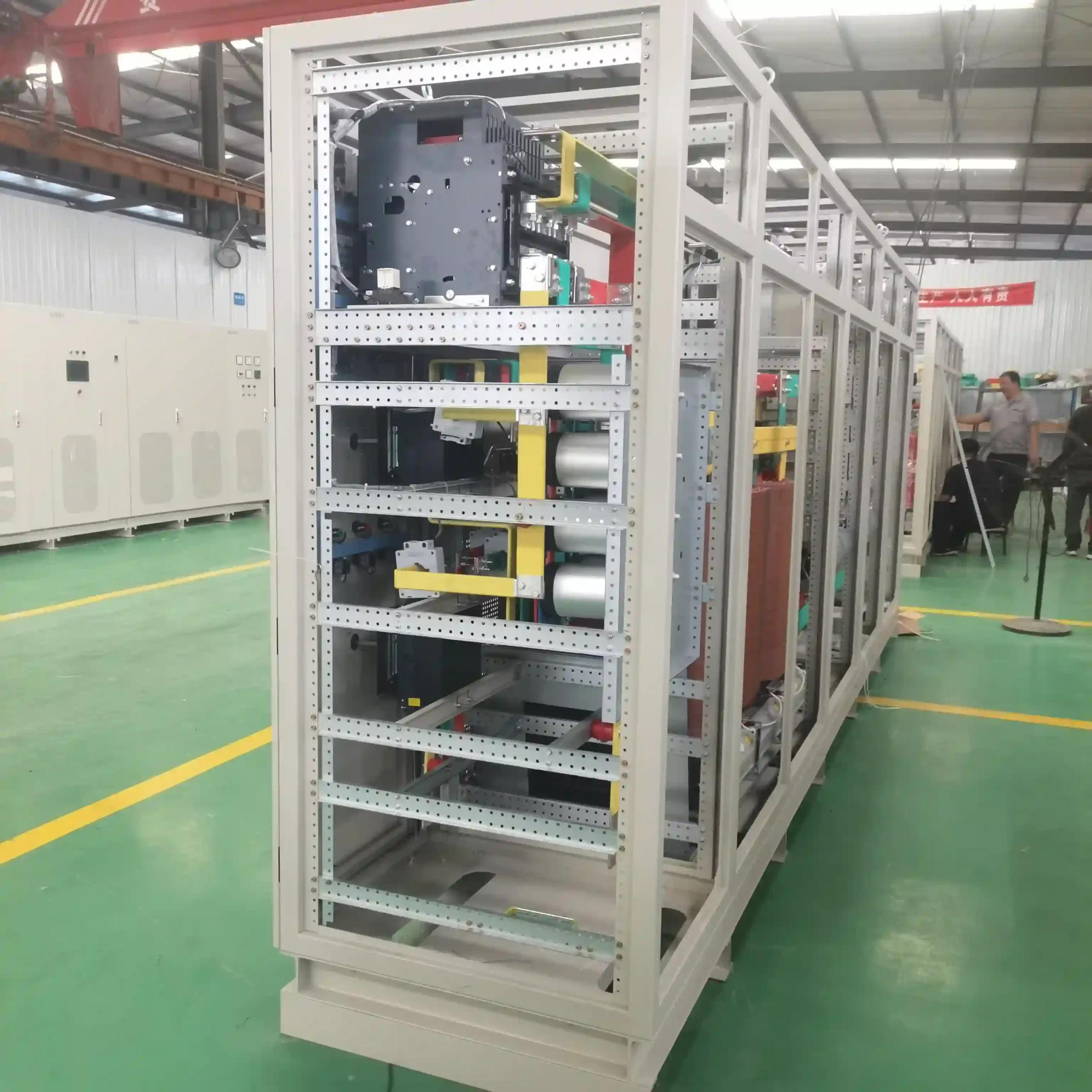
Build the Maintenance Plan Around Required System Functions
A shore power installation is not one maintainable asset. It is a chain of electrical, control, mechanical and interface functions.
Depending on the architecture, the maintenance boundary may include:
- incoming switchgear;
- output switchgear;
- phase-shifting or isolation transformers;
- frequency converter power units;
- cooling fans and HVAC;
- auxiliary power supplies;
- PLC and HMI equipment;
- meters and protection relays;
- communication networks;
- berth connection boxes;
- plugs, sockets and cable systems;
- protective-earth and bonding paths;
- pilot and permissive circuits; and
- emergency-stop and interlock functions.
The wider equipment relationship is explained in our shore power system architecture and components page.
These functions should not be maintained as if they share the same failure mechanism.
Cleaning an air filter does not confirm breaker condition. Exercising a breaker does not confirm the electrical condition of a vessel connector. Replacing a controller does not prove that the approved protection settings and permissive logic have been restored.
Four Different Triggers Should Drive Shore Power Maintenance
Preventive maintenance does not mean that every task needs one fixed calendar interval.
1. Calendar-Based Maintenance
Some work is conveniently planned around annual shutdowns, berth maintenance windows, OEM inspection schedules or coordinated port outages.
Calendar planning is useful because personnel, permits, test equipment and service support can be arranged in advance. Calendar time alone, however, does not describe actual equipment stress.
2. Usage-Based Maintenance
Some equipment accumulates wear mainly when it operates.
Relevant indicators may include:
- converter operating hours;
- cooling-fan operating hours;
- breaker operations;
- contactor operations;
- vessel connection cycles;
- cable-reel cycles; and
- start/stop cycles.
A berth serving frequent vessel calls can accumulate connector wear much faster than another berth installed on the same date.
3. Condition-Based Maintenance
Condition data can indicate whether deterioration is actually developing.
Useful inputs may include:
- temperature trend;
- abnormal thermal rise;
- insulation condition;
- contact condition;
- connector resistance where applicable;
- contamination;
- corrosion;
- airflow;
- breaker operating behaviour;
- repeated alarms;
- mechanical wear; and
- communication stability.
ISO 17359 provides a general framework for machinery condition-monitoring programmes. ISO 18095 addresses condition monitoring of power transformers.
Condition monitoring does not eliminate scheduled maintenance. It provides another input for deciding what needs attention and when.
4. Event-Triggered Maintenance
Some inspections should begin because something happened, not because a date arrived.
Examples include:
- protective trip;
- repeated high-temperature alarm;
- abnormal vessel disconnection;
- power-module failure;
- breaker mechanism abnormality;
- unstable pilot signal;
- earth or bonding fault;
- controller replacement;
- protection-relay replacement;
- major cable repair; or
- unexpected interruption during vessel supply.
Resetting the alarm does not necessarily remove the failure mechanism.
Operating Environment Changes the Maintenance Demand
Identical equipment does not necessarily need identical maintenance attention in every installation.
Maintenance demand can change with:
- load;
- ambient temperature;
- humidity;
- dust;
- corrosive atmosphere;
- salt exposure;
- vibration; and
- operating continuity.
This matters in shore power because equipment may be distributed between conditioned electrical rooms, converter containers, berth-side enclosures, outdoor connection boxes and cable-management equipment exposed directly to the marine atmosphere.
For the environmental protection side of the problem, see shore power corrosion and salt-fog protection .
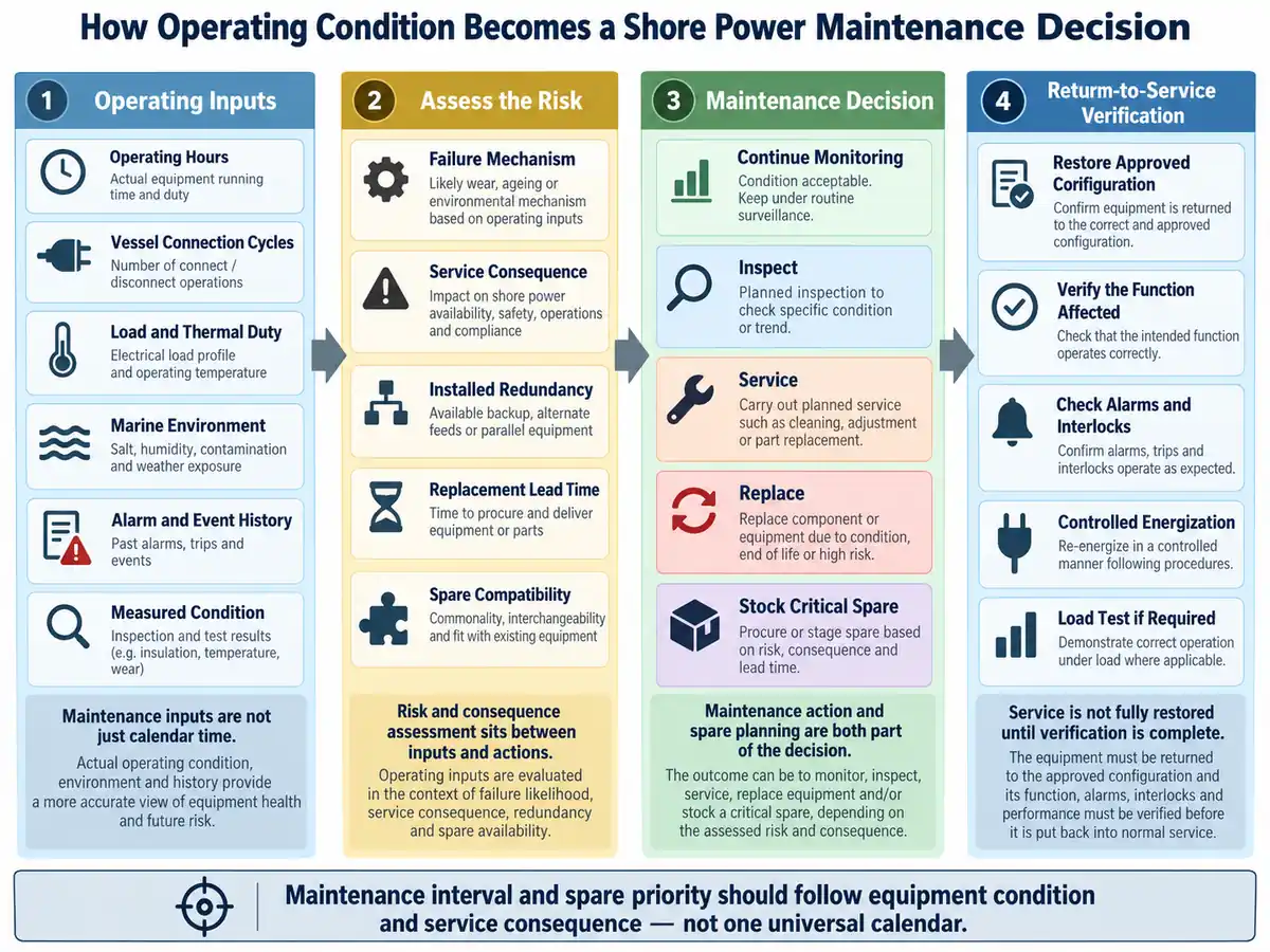
Inspection, Measurement and Functional Test Are Not the Same Thing
A maintenance instruction such as “check the equipment” is too vague. Different maintenance activities answer different engineering questions.
Visual or Physical Inspection
Inspection asks: Is there visible or physical evidence of deterioration?
- corrosion;
- contamination;
- damaged seals;
- loose mechanical parts;
- cable-jacket damage;
- discoloration;
- blocked filters;
- condensation;
- cracked insulation;
- connector wear; and
- abnormal vibration.
Measurement
Measurement asks: Has the electrical, thermal or mechanical condition changed?
- temperature;
- current;
- voltage;
- insulation condition;
- contact or connection resistance;
- operating time;
- mechanism characteristics;
- protective-path continuity; and
- phase balance.
Functional Test
Functional testing asks: Does the required function actually operate?
- breaker operation;
- interlock logic;
- standby cooling transfer;
- pilot permissive;
- emergency stop;
- alarm generation;
- protection trip;
- PLC I/O;
- communication;
- remote indication; and
- controlled energization sequence.
Maintain by Failure Mode, Not Only by Equipment Name
Grouping work orders by equipment is useful. Grouping risk by failure mechanism is more useful for engineering decisions.
| Failure Mechanism | Possible Early Indication | Maintenance Response | Possible Operational Consequence |
|---|---|---|---|
| Cooling degradation | Rising temperature, repeated fan or HVAC alarm | Inspect airflow, filters, fans, HVAC and temperature response | Converter derating or shutdown |
| High-resistance connection | Local heating, discoloration or abnormal measurement | Inspect and verify connection condition | Overheating or interruption |
| Connector corrosion or wear | Unstable connection, resistance change or visible oxidation | Clean, inspect, test or replace | Protective, pilot or permissive problem |
| Breaker mechanism deterioration | Abnormal operating time or mechanism signature | Inspect and functionally test the mechanism | Failed switching or unavailable feeder |
| Protection or configuration error | Unexpected trip, missing permissive or communication mismatch | Restore and verify approved configuration | Incorrect trip or unsuccessful energization |
| Insulation deterioration | Abnormal insulation result or repeated earth-fault indication | Investigate, test and repair | Earth fault or outage |
| Cooling redundancy unavailable | Standby path does not start | Test standby equipment and control logic | Loss of redundancy before primary failure |
| Stored spare incompatible | Hardware or software mismatch found during replacement | Verify part number, revision and configuration in advance | Extended outage despite having spare stock |
Converter Maintenance: Heat, Airflow and Connections
Frequency converters combine power semiconductors, DC-link equipment, bus connections, auxiliary supplies, cooling equipment, fiber communication and control electronics.
Several degradation mechanisms can therefore exist at the same time.
Restricted airflow increases thermal stress. Contamination can reduce cooling effectiveness or affect insulation. Loose electrical connections can create local heating. Cooling fans can deteriorate before complete failure.
Useful maintenance questions include:
- Are cooling paths clear?
- Are fans operating normally?
- Are temperature trends changing under comparable load?
- Are there repeated power-unit or temperature alarms?
- Are bus and power connections showing heat or discoloration?
- Are control and fiber connections secure?
- Are electronic assemblies exposed to contamination or moisture?
- Does the replacement power unit match the approved hardware and control configuration?
For the converter's system role, see the marine frequency converter page.
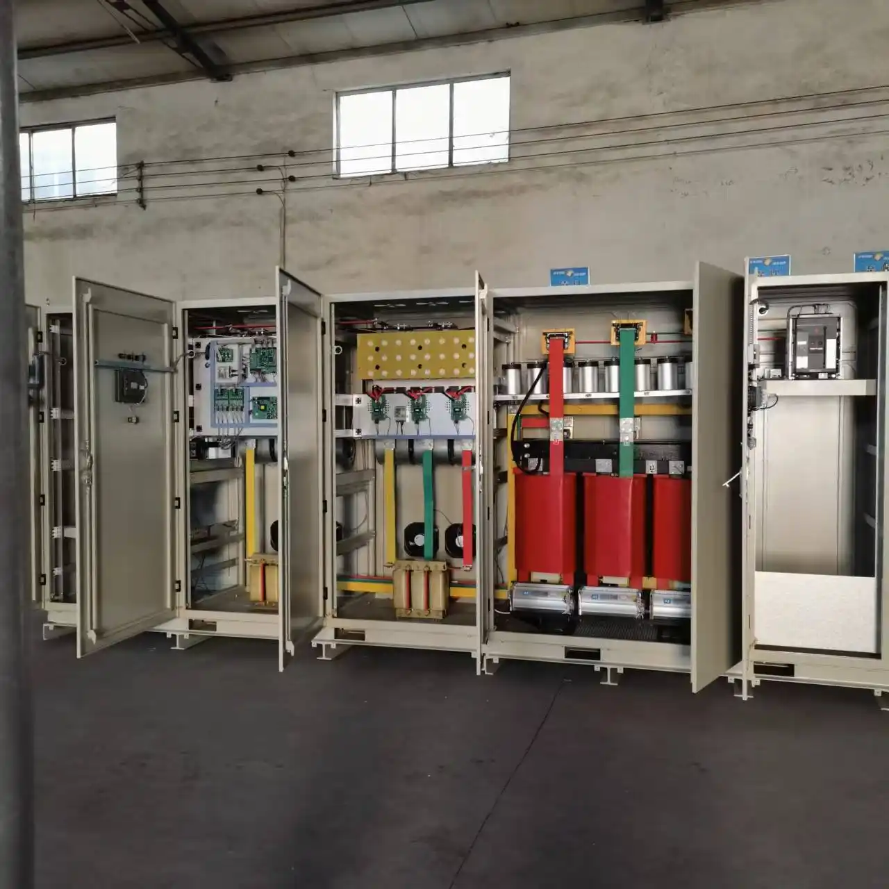
Cooling Equipment Can Determine Whether the Converter Is Available
Cooling equipment does not carry vessel load directly, but loss of cooling can stop the equipment that does.
In one shore power configuration, cooling-system failure generated alarms. If the problem remained unresolved and equipment temperature continued to rise to the configured limit, the converter would stop.
Cooling maintenance should therefore consider more than whether a fan is rotating during a single inspection.
- Is airflow adequate?
- Are filters restricting flow?
- Is the condenser or heat exchanger clean?
- Are fan bearings or vibration changing?
- Are temperature alarms becoming more frequent?
- Does the standby cooling path start when required?
- Are auxiliary power sources available where redundancy is provided?
Installed Redundancy Is Not the Same as Available Redundancy
Installed redundancy is a design feature.
Available redundancy is an operating condition.
A system may contain:
- redundant fans;
- dual auxiliary supplies;
- spare power units;
- parallel communication paths;
- multiple berth feeds; or
- standby converter capacity.
The presence of a second component does not prove that it will operate when the first one fails.
Maintenance should therefore ask:
- When was the standby path last operated?
- Does automatic transfer still work?
- Does the standby device produce the expected status and alarms?
- Does the backup controller contain the current configuration?
- Is the spare module compatible with the installed revision?
- Has a normally idle mechanism become stiff or difficult to operate?
- Can reduced-capacity operation actually be established?
Switchgear Maintenance Requires Mechanical, Electrical and Protection Checks
Switchgear introduces another set of failure mechanisms.
Required functions can include:
- carrying current;
- interrupting faults;
- opening and closing on command;
- maintaining insulation;
- providing position feedback;
- enforcing interlocks; and
- executing protection logic.
Useful indicators can therefore include:
- breaker operation count;
- operating mechanism condition;
- contact condition;
- coil-current behaviour;
- mechanism operating speed;
- temperature rise;
- protection-relay status;
- interlock operation;
- auxiliary-contact feedback; and
- cabinet environment.
Condition monitoring can therefore provide more useful information than simply asking whether the breaker opened and closed during today's test.
Transformer Maintenance Should Follow Its Own Condition Profile
Transformer maintenance should not be copied from the converter checklist.
Relevant condition indicators may include:
- winding temperature;
- fan operation;
- connection condition;
- contamination;
- insulation condition;
- abnormal sound;
- signs of overheating;
- protection alarms; and
- service history.
In one shore power configuration, transformer temperature was monitored directly, with high-temperature alarm, overtemperature trip and cooling-fan fault indication available to the control system.
The exact electrical tests and maintenance intervals should follow the transformer construction, voltage class, OEM documentation and project procedure.
The Berth Connection Is Both an Electrical Interface and a Wear Component
Shore connection equipment experiences conditions that enclosed electrical equipment may not.
Every vessel call can introduce:
- plugging and unplugging cycles;
- mechanical handling;
- cable movement;
- connector loading;
- moisture;
- contamination;
- salt exposure; and
- wear on seals and locking devices.
Plugs, sockets, cable-reel slip rings, pilot contacts, protective conductors, strain relief and enclosure seals therefore belong in the preventive-maintenance programme.
A connector can look mechanically engaged while its electrical condition has deteriorated.
Visual inspection alone may therefore be insufficient for some maintenance conditions.
For the complete connection sequence and interface checks, see the shore power connection procedure .
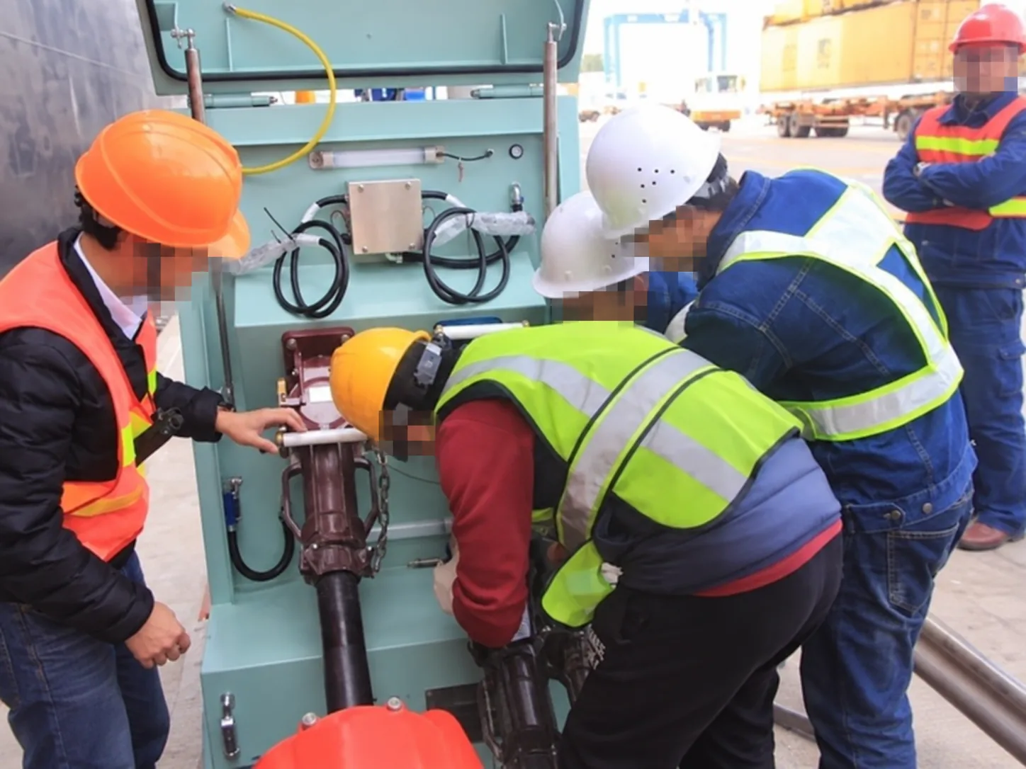
Move from Alarm History Toward Condition-Based Maintenance
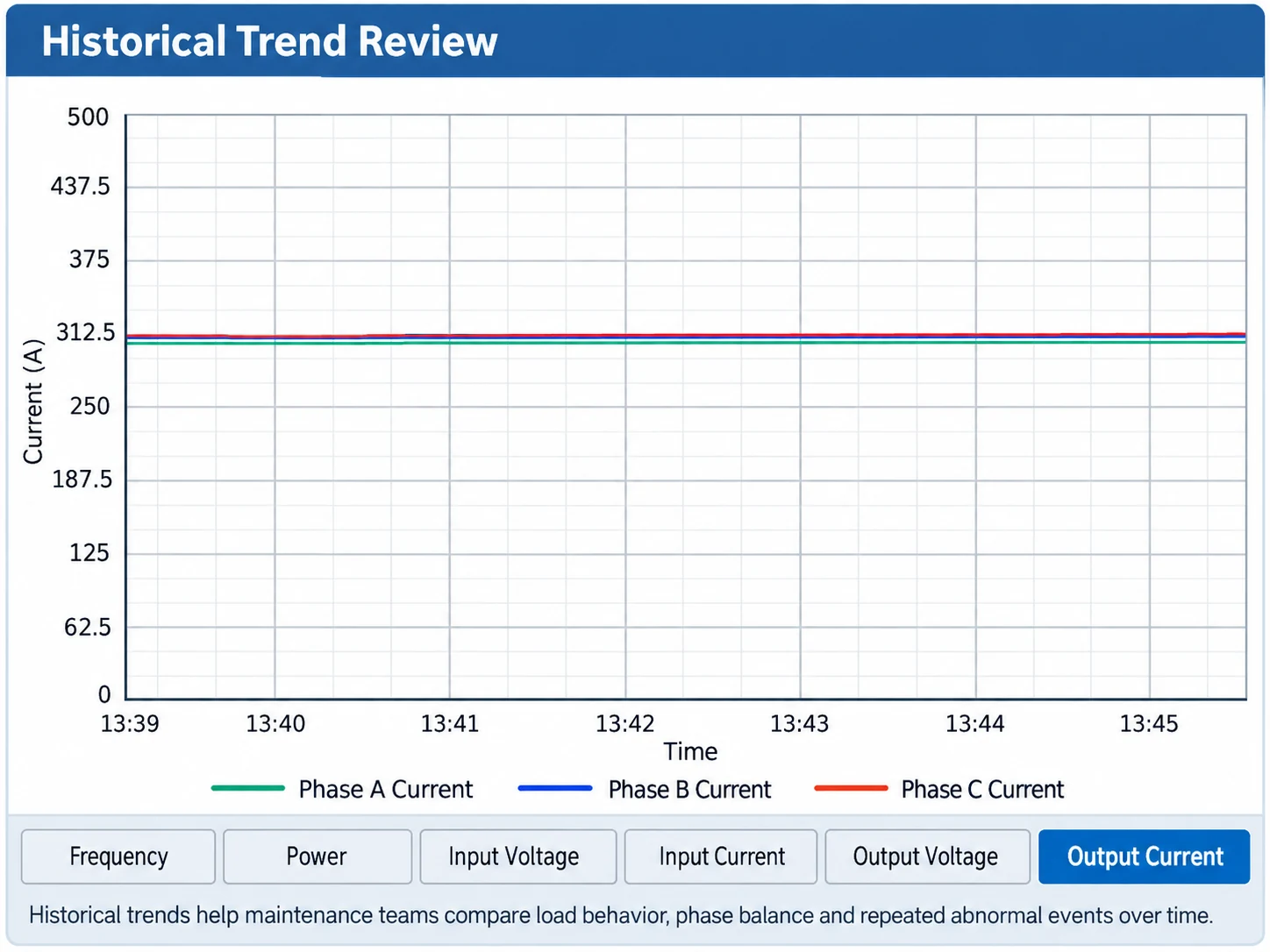
A modern monitoring system can create more maintenance value than a single alarm indication.
Historical operating data can help identify deterioration that is not obvious during one inspection.
Useful information may include:
- voltage and current;
- load;
- temperature;
- breaker state;
- protection events;
- fault history;
- parameter changes;
- alarms;
- operating logs; and
- trend curves.
This changes the maintenance question from “Is there an alarm now?” to:
- Has this alarm appeared repeatedly?
- Does it occur at the same load?
- Is the temperature trend gradually increasing?
- Does one berth generate more pilot interruptions than another?
- Is breaker operating behaviour changing?
- Did the problem begin after a controller or settings change?
- Does a fault repeat under the same connection condition?
Alarm Data Need Context Before They Become Maintenance Evidence
More data do not automatically produce better maintenance decisions.
A high-temperature alarm, for example, can mean different things depending on:
- vessel load;
- ambient temperature;
- fan status;
- filter condition;
- HVAC operation; and
- previous temperature history.
Similarly, a pilot interruption can originate from the berth connector, cable movement, pilot contact condition, wiring, interlock logic or the vessel-side interface.
Useful maintenance records therefore connect an event to:
- time;
- operating mode;
- load;
- berth;
- connected vessel;
- ambient condition;
- equipment state;
- preceding alarms;
- maintenance action; and
- condition after repair.
Critical Spare Does Not Mean “Most Expensive Spare”
Criticality is about recovery risk, not purchase price.
A relatively inexpensive control power supply, fan, communication module or protection relay can stop an entire berth if there is no redundant function, no compatible replacement and supplier lead time is longer than the acceptable outage.
A large transformer may be much more expensive and still be impractical to hold as a complete on-site spare.
Four Useful Classes of Shore Power Spares
Class A — Immediate Recovery Spares
These are components where a relatively small failure can stop service and rapid replacement is practical.
- cooling fans;
- control power supplies;
- fuses;
- contactors;
- selected communication modules;
- relays;
- approved power modules; and
- selected connector components.
The objective is rapid recovery.
Class B — Configuration-Controlled Spares
The hardware may be available, but correct operation depends on revision, configuration or software.
- PLC hardware;
- HMI units;
- protection relays;
- controller boards;
- gate-drive boards;
- communication modules; and
- selected converter power units.
For these parts, record:
- part number;
- hardware revision;
- firmware;
- parameter file;
- communication settings;
- approved substitute; and
- required backup configuration.
A physically compatible component is not necessarily a functionally compatible component.
Class C — Consumable and Environmental Spares
These parts are strongly influenced by contamination, wear or exposure.
- filters;
- seals;
- fuses;
- connector wear parts;
- selected cooling components; and
- other approved consumable items.
Their inventory level is often driven by usage and environment.
Class D — Strategic Recovery Items
Some components are critical but expensive, large or slow to replace.
- complete transformers;
- major switchgear assemblies;
- large converter sections; or
- specialised connection equipment.
Holding a complete spare is not always the best answer.
Alternatives may include:
- repair agreements;
- supplier-held stock;
- common spares across multiple berths;
- standby equipment;
- temporary reduced-capacity operation; or
- defined emergency-recovery procedures.
The correct strategy depends on acceptable outage time.

Spare Inventory Should Include Obsolescence and Storage Risk
A spare is not available simply because it exists in a warehouse.
Long-term storage introduces its own risks:
- moisture;
- corrosion;
- dust;
- depleted batteries;
- damaged packaging;
- degraded seals;
- obsolete firmware;
- obsolete software tools;
- lost parameter files; and
- hardware revision mismatch.
Critical electronic-spare records should therefore include, where relevant:
- manufacturer;
- part number;
- hardware revision;
- firmware or software version;
- installed-system compatibility;
- storage condition;
- preservation requirement;
- test requirement;
- shelf-life requirement;
- configuration backup location; and
- approved replacement procedure.
A Practical Spare Criticality Decision
Before adding a component to the critical-spare list, ask the following questions.
| Decision Question | Why It Matters |
|---|---|
| Will failure stop vessel service? | Establishes service consequence. |
| Is there installed redundancy? | Shows whether operation can continue. |
| Has that redundancy been functionally verified? | Distinguishes installed from available redundancy. |
| How long is procurement lead time? | Determines outage exposure. |
| Can the component be repaired locally? | Changes the recovery strategy. |
| Is the spare configuration-specific? | Controls replacement compatibility. |
| Does it deteriorate in storage? | Determines preservation requirements. |
| Can it be tested before it is needed? | Improves readiness confidence. |
| Can one spare serve multiple berths? | Affects inventory strategy. |
| Can the system operate at reduced capacity? | May lower stock priority. |
| What outage can the port tolerate? | Converts technical failure into an operational consequence. |
Return-to-Service Verification Must Match the Maintenance Work
Replacing the failed component is not the end of the maintenance task.
Maintenance itself can introduce new errors.
- wiring returned to the wrong terminal;
- incorrect phase sequence;
- wrong relay settings;
- incorrect CT or VT ratio;
- outdated PLC programme;
- communication-address mismatch;
- interlock not restored;
- temporary bypass left in place;
- wrong module configuration; or
- loose connection after reassembly.
Return-to-service testing should therefore be based on what function was disturbed by the maintenance work.
Return-to-Service Verification Matrix
| Maintenance Performed | Verification Focus |
|---|---|
| Cooling fan, filter or HVAC work | Airflow, fan direction, alarms and temperature response |
| Converter power-unit replacement | Hardware compatibility, configuration, communication and controlled energization |
| Control power-supply replacement | Correct voltage, downstream control availability and alarms |
| Protection-relay replacement | CT/VT ratios, settings, communication and trip logic |
| Breaker mechanism maintenance | Open/close operation, position feedback, interlocks and affected protection |
| Berth connector maintenance | Mechanical locking, pilot function, protective path and applicable electrical measurements |
| Cable or main termination work | Connection integrity, phase sequence and applicable insulation checks |
| PLC or controller replacement | Approved program, parameters, I/O, communication and permissives |
| Communication equipment replacement | Addressing, data path and alarm/status transmission |
| Major converter repair | Controlled energization and staged load verification where required |
| Major protection or control change | Functional alarm, trip and interlock verification before vessel supply |
Do Not Repeat a Full FAT After Every Repair
Maintenance verification should be proportional to the work performed.
Replacing a cabinet filter does not require a complete shore power FAT. Changing a major converter assembly or protection chain may require significantly more verification.
Major system verification can include functions such as:
- controlled energization;
- voltage and current verification;
- progressive loading;
- load rejection;
- overload response;
- phase unbalance;
- waveform behaviour;
- frequency response;
- alarm operation; and
- protection checks.
For the broader system verification framework, see shore power manufacturing and FAT .
Maintenance Records Should Change the Next Maintenance Decision
Maintenance history has little value if it only proves that a work order was closed.
A useful maintenance record can include:
- operating hours;
- breaker operations;
- vessel connection cycles;
- condition before work;
- alarm history;
- measurement before work;
- component replaced;
- hardware revision;
- software or settings restored;
- measurement after work;
- functional checks completed;
- outstanding defects;
- return-to-service approval; and
- recommended follow-up.
Repeated Filter Contamination
If filters become heavily contaminated before the planned interval, the response may be to shorten the interval, investigate enclosure sealing, improve filtration or review environmental control.
Repeated Connector Deterioration
If the same berth connection repeatedly develops corrosion or resistance problems, consider water ingress, handling practice, connector alignment, sealing, cable strain and environmental exposure.
Repeated Standby Failure
If standby cooling or another redundant subsystem repeatedly fails testing, the operating strategy should be updated until standby capability has been restored.
Maintenance Decision Matrix
A practical maintenance programme connects observed condition directly to the next engineering action.
| Observed Condition | Engineering Question | Typical Response |
|---|---|---|
| Stable condition, no abnormal trend | Is present surveillance sufficient? | Continue monitoring |
| Early deterioration indication | Is more evidence needed? | Inspect or measure |
| Condition outside preferred range but function remains available | Can deterioration be corrected during a planned outage? | Service |
| Condition beyond the approved acceptance limit | Can the component remain in service under the approved procedure? | Repair or replace |
| Repeated alarm without trip | What failure mechanism may be developing? | Investigate trend and root cause |
| Protective trip | Has the initiating condition been identified? | Diagnose before return to service |
| Redundant path fails test | Is redundancy actually available? | Restore standby capability |
| Critical component has long lead time | Does outage exposure exceed tolerance? | Stock spare or define recovery plan |
| Major component replaced | Has the affected function been verified? | Controlled return-to-service testing |
Acceptance thresholds should come from OEM documentation, applicable standards, project procedures and approved engineering limits.
Common Shore Power Maintenance Mistakes
Using One Interval for the Entire System
The converter, transformer, breaker and berth connector do not share one failure mechanism.
Maintaining Only the Main Power Equipment
Cooling, control power, communication and pilot circuits can also remove the berth from service.
Treating Redundancy as Permanent
Standby functions require inspection and functional verification.
Buying Spares Without Configuration Control
A spare that cannot be installed, configured or commissioned quickly does not provide the expected recovery capability.
Resetting Repeated Alarms Without Trend Analysis
Repeated alarms can indicate progressive deterioration and should be reviewed in their operating context.
Returning to Service Without Functional Verification
A successful repair can still leave a wiring, setting, communication, interlock or configuration error.
What Should Be Included in the Shore Power Maintenance Plan?
Asset and Configuration Information
- equipment list;
- manufacturer;
- model;
- serial number where required;
- hardware revision;
- software or firmware version;
- approved drawings;
- protection settings;
- controller backups; and
- communication configuration.
Maintenance Trigger
For each task, define whether it is:
- calendar based;
- operating-hour based;
- operation-cycle based;
- condition based; or
- event triggered.
Inspection or Test Method
State whether the task requires:
- visual inspection;
- measurement;
- functional test;
- diagnostic test;
- cleaning;
- adjustment;
- replacement; or
- controlled energization.
Acceptance Boundary
Where applicable, define:
- OEM limit;
- approved project limit;
- alarm threshold;
- trip threshold;
- wear limit;
- resistance limit;
- insulation criterion; or
- functional pass/fail requirement.
Required Spare or Recovery Method
For each critical function, identify whether recovery depends on:
- on-site spare;
- shared spare;
- supplier stock;
- repair contract;
- standby equipment;
- reduced-operation method; or
- emergency replacement procedure.
Return-to-Service Requirement
Define the verification required after major maintenance activities before the failure occurs, rather than deciding the verification scope for the first time during an outage.
Information Needed Before Building the Maintenance Strategy
A useful maintenance programme cannot be built from rated kVA alone.
Collect:
- final equipment list;
- final single-line diagram;
- converter architecture;
- transformer type;
- switchgear type;
- connection-system design;
- operating hours;
- expected vessel calls;
- connection cycles;
- load profile;
- environmental condition;
- cooling arrangement;
- installed redundancy;
- protection configuration;
- PLC/HMI configuration;
- alarm and event history;
- previous maintenance records;
- existing critical spares;
- supplier lead times;
- acceptable outage time;
- OEM maintenance documentation; and
- required return-to-service tests.
Frequently Asked Questions
How often should a shore power system be maintained?
There is no single interval for the complete system. Use the equipment manufacturer's requirements together with operating hours, connection cycles, environmental exposure, condition data and failure history.
Is annual preventive maintenance enough?
Not necessarily. Annual maintenance can be one layer of the programme. High operating hours, frequent vessel connections, harsh marine exposure or deteriorating condition may require additional usage-based or condition-based attention.
What is condition-based maintenance for shore power?
It means using observed equipment condition to help decide maintenance timing and scope. Examples include temperature trends, breaker operating characteristics, repeated alarms, connector condition and other approved diagnostic indicators.
What is the difference between inspection and testing?
Inspection identifies visible or physical deterioration. Measurement determines electrical, thermal or mechanical condition. Functional testing confirms that a required function such as an interlock, alarm, trip or standby transfer actually works.
Which shore power spare parts are most critical?
The most critical parts are those whose failure creates unacceptable service loss and whose recovery time exceeds the allowed outage. Price alone does not determine criticality.
Should a port keep a complete spare frequency converter?
Not automatically. The decision depends on converter architecture, module-level replaceability, installed redundancy, failure consequence, supplier lead time and required recovery time.
Should spare power modules and controllers be tested in storage?
Follow the OEM requirements. Where inspection or periodic testing is permitted, it can help confirm storage condition and compatibility. Configuration backups, revisions and software versions should also remain controlled.
Does a redundant system require less maintenance?
Not necessarily. Redundancy can reduce immediate service consequence, but the standby path still has to remain functional. A redundant component that has not been tested may fail when it is finally required.
Do berth plugs and sockets need electrical checks?
They may. Mechanical condition, locking, seals, pilot function, protective paths and electrical resistance can all be relevant depending on the connection design and approved maintenance procedure.
Is a load test required after every repair?
No. Verification should match the work performed. Minor maintenance may require only a focused functional check. Major converter, protection or power-circuit work may justify controlled energization and staged load testing.
What should be verified after replacing a relay or controller?
Restore the approved configuration first. Then verify the affected settings, ratios, communication, I/O, control logic, interlocks, alarms and trip or permissive functions before normal service resumes.
Technical References
- ISO 17359:2018 — Condition monitoring and diagnostics of machines — General guidelines
- ISO 18095:2018 — Condition monitoring and diagnostics of power transformers
- IEC/IEEE 80005-1 — High Voltage Shore Connection systems
- IEC/IEEE 80005-3 — Low Voltage Shore Connection systems
- ABB — Preventive Maintenance for Drives
Standards and OEM documents have their own application scope. Project-specific maintenance intervals, acceptance limits and test methods should be confirmed against the actual installed configuration and approved project documentation.
Plan Maintenance Before the First Failure
A shore power maintenance programme should be designed before an unavailable component interrupts vessel service.
The programme should connect:
equipment function → failure mechanism → condition indicator → maintenance trigger → maintenance action → critical spare or recovery plan → return-to-service verification
For an engineering review, provide:
- final equipment list;
- operating duty and vessel-connection frequency;
- berth and environmental conditions;
- installed redundancy;
- alarm and maintenance history;
- existing critical-spare inventory;
- supplier lead times; and
- acceptable outage time.
SDACME can use these inputs to review the maintenance scope, critical-spare strategy and return-to-service verification requirements for the actual shore power system.
Send Your Project Requirements