
How to Calculate Short-Circuit Current in a Shore Power System
Short-circuit current in a shore power system cannot be determined from the converter kVA rating alone.
The calculation depends on the available short-circuit capacity of the port grid, transformer impedance, system voltage, cable impedance and the location of the fault.
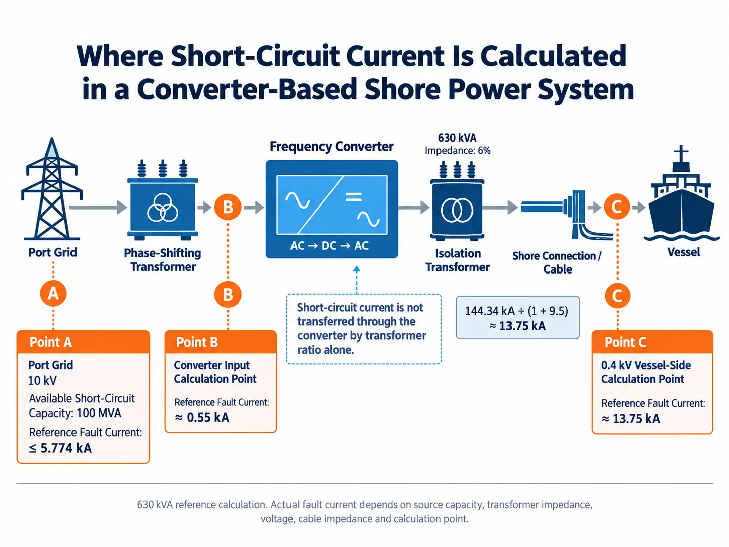
A frequency-converter-based shore power system also introduces an important calculation boundary. The input side and vessel side cannot simply be treated as one continuous transformer-fed network.
Start with the Available Short-Circuit Capacity
The calculation begins with the electrical conditions at the shore connection point.
Typical input data includes:
- Shore-grid voltage
- Available short-circuit capacity
- Operating condition used for the calculation
- Upstream transformer information
- Feeder arrangement
- Location of the calculation point
In one engineering reference, the shore supply for a 630 kVA system was 10 kV and the minimum short-circuit capacity used for the calculation was 100 MVA.
Under that stated condition, the three-phase short-circuit current at the 10 kV supply point was approximately:
That value describes the selected shore-grid calculation point.
It does not mean that 5.774 kA will also appear after the transformer, at the converter output or at the vessel connection.
Every section of the power path has to be considered according to its own voltage and impedance.
Divide the Calculation at the Frequency Converter
This is one of the most important differences between a conventional transformer-fed distribution system and a frequency-converter-based shore power system.
The frequency converter changes the electrical structure of the system.
Incoming AC power passes through the input transformer and converter stage before a new AC output is produced for the vessel. Because of this conversion process, fault-current calculation should distinguish between:
- The grid and converter input side
- The converter output and vessel side
The fault current should not simply be transferred from one side to the other by applying a transformer ratio.
For a broader view of where the transformers, converter and switchgear sit in the electrical path, see our shore power system architecture and components page.
Transformer Impedance Changes the Available Fault Current
Transformer impedance is a major part of a short-circuit calculation.
The transformer does not behave as an ideal connection between two voltage levels. Its impedance limits the current that can flow during a downstream short circuit.
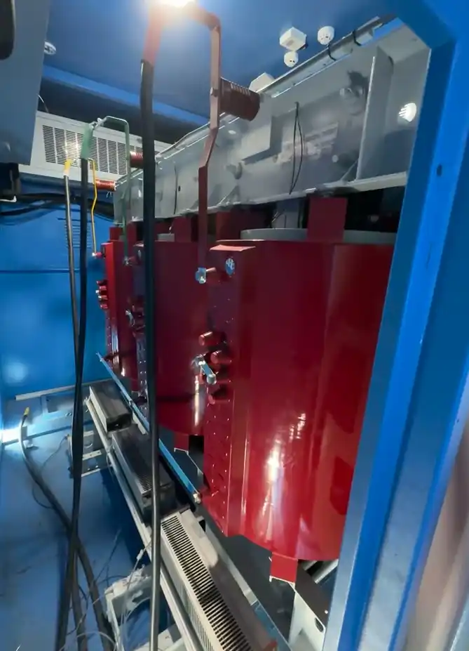
In the engineering calculations used for this article, transformer impedance was converted to the selected common calculation base before the total system impedance was determined.
A simplified calculation therefore follows this logic:
The result changes whenever the transformer rating, percentage impedance or calculation base changes.
This is why two shore power systems with similar output voltage can still have different short-circuit currents.
A 630 kVA Shore Power Calculation Example
One 630 kVA shore power engineering reference used:
- Shore-grid voltage: 10 kV
- Calculation base: 100 MVA
- Shore-side three-phase fault current: approximately 5.774 kA
- Isolation transformer capacity: 630 kVA
- Transformer impedance voltage: 6%
- Vessel-side calculation voltage: 0.4 kV
For the converter input section, the transformer impedance was included in the common-base calculation.
The resulting short-circuit current at the converter input calculation point was approximately:
The low-voltage vessel-side calculation was then treated separately.
At 0.4 kV, the base short-circuit current used in the calculation was:
The 630 kVA isolation-transformer impedance corresponded to a per-unit value of approximately:
Together with the other simplified system impedance used in that calculation, the total was:
The resulting vessel-side short-circuit current was therefore approximately:
10 kV shore side: ≤ 5.774 kA
Converter input section: ≤ 0.55 kA
0.4 kV vessel side: ≤ 13.75 kA
These are calculation results from one defined 630 kVA system.
They are not standard short-circuit-current values for every 630 kVA shore power installation.
Change the source fault level, transformer impedance, voltage or system arrangement and the result changes.
Why a 500 kVA System Gives a Different Result
A second engineering reference used a 500 kVA shore power arrangement.
The input conditions were:
- Shore supply: 6 / 6.6 kV
- Minimum short-circuit capacity: 100 MVA
- Three-phase input fault current: approximately 9.622 kA at 6 kV and 8.747 kA at 6.6 kV
- Isolation-transformer capacity: 500 kVA
- Transformer impedance voltage: 6%
- Low-voltage calculation point: 0.4 kV
For the 500 kVA isolation transformer, the impedance on the 100 MVA calculation base was:
With the additional simplified system impedance used in the calculation:
Using the same 0.4 kV base short-circuit current of 144.34 kA, the vessel-side result was approximately:
This comparison is useful because the two systems do not produce the same result simply because both supply low-voltage power to a vessel.
Transformer capacity and impedance are part of the calculation.
So are the grid conditions and the location at which the fault current is being evaluated.
Do Not Automatically Ignore Cable Impedance
The reference calculations treated the selected copper-cable impedance as negligible where the conductor sizing and project arrangement made that simplification acceptable.
That assumption should not automatically be transferred to another project.
The cable arrangement should first be reviewed using the actual:
- Conductor material
- Cross-section
- Length
- Route
- Vessel connection arrangement
- Calculation point
If cable impedance is included, the total impedance between the source and fault location changes.
The resulting short-circuit current changes with it.
This becomes particularly important when the berth arrangement, cable length or connection point differs significantly from the reference calculation.
Our shore power selection and compatibility guide explains why cable distance and conductor information should be confirmed during system selection rather than after the equipment has already been finalized.
Short-Circuit Calculation and Protection Settings Must Be Reviewed Together
A short-circuit calculation is not only a number for the design report.
Its result has to be checked against the electrical equipment and protection arrangement.
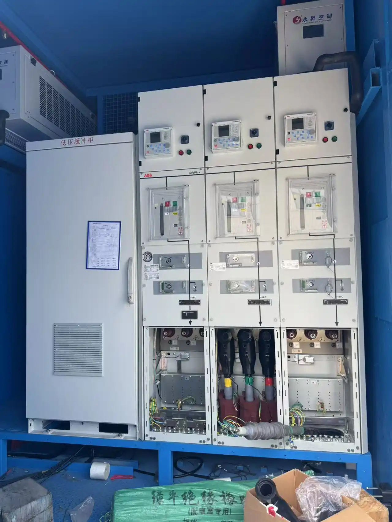
The shore power engineering reference used high-voltage switchgear with project-defined breaker ratings and included protection functions such as:
- Overcurrent protection
- Earth or grounding protection
- Overvoltage protection
- Undervoltage protection
- Reverse-power protection
- Phase-unbalance protection
The relevant switchgear, protection devices and settings have to correspond to the electrical conditions at their own installation point.
For example, the current calculated on the 10 kV shore side is not the same as the current calculated at the low-voltage vessel connection.
Using one short-circuit-current figure for every breaker in the system would therefore ignore the actual network arrangement.
For the broader relationship between electrical ratings, protection and project requirements, see our shore power standards and compliance page.
State the Calculation Conditions, Not Just the Final kA Value
A short-circuit-current figure without its calculation conditions is easy to misuse.
Instead of reporting only 13.75 kA, the engineering record should make clear that this result belongs to a particular combination of:
- System capacity
- Source voltage
- Source short-circuit capacity
- Calculation base
- Transformer capacity
- Transformer impedance
- Output voltage
- Included or excluded cable impedance
- Fault location
The same applies to the 11.1 kA result from the 500 kVA calculation.
The number is useful because the assumptions behind it are known.
If those assumptions change, the calculation should be reviewed rather than reusing the old result.
What to Verify During FAT and Commissioning
The actual port short-circuit condition is defined by the installation and cannot be reproduced simply by running the equipment in a factory.
Factory testing can, however, verify the protection and control functions built around the approved design.
The engineering test procedure behind this article includes checks such as:
- Input-current measurement and calibration
- Protection signal verification
- Overcurrent-related protection checks
- Zero-sequence protection checks
- Breaker operation
- Control and protection indication
The test values used for one project should not automatically become the settings for another system.
During site commissioning, the final wiring, protection parameters and equipment interfaces should be checked against the approved project documents.
If settings are changed during commissioning, the final values should be recorded with the as-built system information.
Information Needed for a Shore Power Short-Circuit Study
Before the calculation is finalized, provide as much of the following information as possible:
- Shore-grid voltage and frequency
- Available short-circuit capacity at the supply point
- Shore single-line diagram
- Upstream transformer and feeder information
- Frequency-converter configuration
- Transformer ratings
- Transformer impedance
- Output voltage
- Cable sizes and lengths
- Vessel connection arrangement
- Switchgear ratings
- Protection configuration
- Required calculation points
The calculation can then follow the actual power path instead of assuming that one fault-current value represents the complete shore power system.
Frequently Asked Questions
Is shore power short-circuit current determined by converter kVA?
No. System capacity alone is not enough. The result depends on the source short-circuit condition, system voltage, transformer impedance, cable arrangement and fault location.
Can the port substation short-circuit current be used directly for the vessel connection?
No. The vessel-side calculation is separated from the shore-grid calculation by transformers and, in a converter-based system, the frequency-conversion stage. The correct calculation has to follow the actual electrical architecture.
Why are the converter input and vessel-side currents different?
They are calculated at different points in the system and at different voltage levels, with different impedances included. In the 630 kVA reference, the calculation produced approximately 0.55 kA at the converter input section and approximately 13.75 kA at the 0.4 kV vessel-side point. Those figures belong to the stated calculation conditions.
Is transformer impedance important in the calculation?
Yes. The engineering references used 6% impedance for the isolation transformers, and that impedance formed a major part of the calculated downstream system impedance. Changing the transformer rating or impedance changes the result.
Can cable impedance always be ignored?
No. It was treated as negligible in the referenced simplified calculations under the stated cable conditions. Another project should review its own conductor size, material, length and connection arrangement before making the same assumption.
Does the same short-circuit-current value apply to every shore power project?
No. The 0.55 kA, 13.75 kA and 11.1 kA values in this article are examples from defined engineering calculations. They demonstrate the calculation method and the importance of the calculation boundary. They are not universal design values.
Discuss Your Shore Power Protection Requirement
Send us the shore single-line diagram, source short-circuit data, transformer ratings and impedance, cable information, converter configuration and vessel-side voltage.
We can review the calculation points together with the switchgear and protection arrangement before the final shore power configuration is confirmed.
Contact Our Engineering Team