
What a Shore Power Monitoring and SCADA System Should Show
A shore power monitoring system should let the operator follow the electrical path from the port grid to the vessel, understand why an operation is permitted or blocked, and reconstruct what happened when a trip occurs.
Showing voltage, current and a green running light is not enough.
A useful system combines real-time electrical measurements, breaker and interlock status, alarms, event records, historical trends, energy metering and controlled operating commands.
The required scope depends on the installation. A standalone shore power converter may only need a local PLC and HMI. A multi-berth port installation may require central SCADA, remote operating stations, energy metering and interfaces with the port's existing electrical-management system.
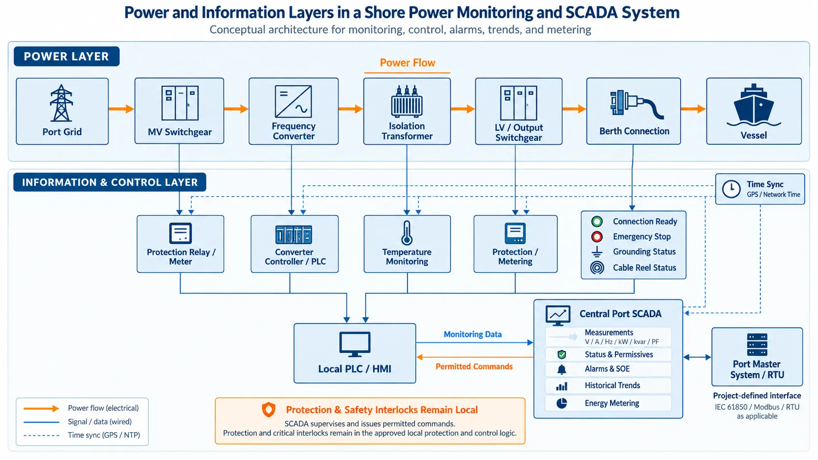
Separate the Power Layer from the Information Layer
The power layer includes the shore-grid feeder, transformers, frequency converter, switchgear, berth connection equipment and vessel.
The information layer observes and coordinates those assets through meters, protection relays, sensors, PLCs, HMIs and communication networks.
These two layers should not be confused.
A SCADA screen can show that an overcurrent condition has occurred, but the protective action should still be carried out by the approved protection and control system. Remote supervisory control should operate through the local protection and interlock logic rather than replace it.
Protection handles time-critical electrical actions. Monitoring tells the operator what is happening. Supervisory control sends permitted commands only after the required operating conditions have been satisfied.
For the relationship between the converter, transformers, switchgear, berth connection and control system, see our shore power system architecture and components page.
Real-Time Measurements Need a Clear Location
An operator normally needs to see voltage, current and frequency, but those values are only useful when the measurement point is clear.
A shore power installation may have a medium-voltage grid input, converter-side measurements and a 400 V or 440 V vessel feeder. A screen that simply displays “Voltage: 440 V” does not tell the operator enough.
The HMI should identify both the equipment and the side being measured.
Typical operating measurements can include:
- Three-phase voltage
- Three-phase current
- Frequency
- Active power
- Reactive power
- Power factor
- Active energy
- Reactive energy
- Voltage or current unbalance
- Transformer temperature
- Converter or cabinet temperature
- Selected equipment and environmental status
In one shore power project delivered with project partners, the monitoring scope included three-phase voltage and current, active and reactive power, power factor, energy, operating frequency, transformer temperature and breaker status.
Not every signal needs to appear on the main overview.
The main screen should show the information required for normal operation. Detailed pages can contain transformer temperatures, converter information, communication diagnostics, historical records and maintenance data.
A well-designed HMI allows an operator to understand the electrical condition quickly without searching through hundreds of low-value signals.
Show Why a Command Is Permitted or Blocked
Showing whether a breaker is open or closed is useful.
Showing why it cannot close is more useful.
Before a shore power system supplies a vessel, several conditions may need to be satisfied. Depending on the system design, the operator may need confirmation of breaker position, earthing-switch position, emergency-stop status, converter readiness and the state of the berth connection.
In the jointly delivered project referenced here, monitored status points included:
- Cable connection ready
- Emergency disconnect status
- Grounding status
- Cable-reel pay-out and retrieval signals
- High-voltage switchgear position
- Shore power converter operating and fault status
The same project documentation also included remote functions such as high-voltage breaker open/close commands and shore power converter start, stop and reset commands.
These commands should not be treated as unrestricted buttons.
If the connection condition is not proven, an emergency stop is active or the equipment is not in the permitted operating position, the HMI should make the blocked condition understandable to the operator.
A generic message such as “Operation Not Allowed” is much less useful than showing the missing permissive.
The purpose of the screen is not only to display equipment status. It should help the operator understand the operating sequence.
Alarm Records Should Show What Happened First
A long alarm list does not automatically make fault diagnosis easier.
When one fault causes several secondary alarms, the sequence matters.
A cooling fan failure, for example, may occur first. Equipment temperature then rises, a high-temperature alarm appears and the converter finally trips.
If the operator only sees the final trip, the high-temperature condition may appear to be the original cause.
Alarm and event records should therefore identify the source and time of the event clearly. Depending on the project, the records may also include alarm category, priority and acknowledgement status.
Sequence-of-events, or SOE, records are especially useful when several switchgear, protection and control signals change within a short period.
SCADA functions documented for the jointly delivered project included remote-status processing, fault information, operating records, protection information, remote control and event handling.
The practical question is not simply “Does the system have alarms?” It is “Can the operator reconstruct the sequence that caused the shutdown?”
Historical Trends Turn Data into Diagnostic Evidence
Historical trends are useful for more than displaying monthly energy consumption.
An engineer can compare output current with transformer temperature, review voltage during a vessel load change or see whether cabinet temperature has gradually increased over several operating periods.
Trend data can also help determine whether an event originated from the shore equipment or from a change in vessel load.
The recording interval should match the signal.
Transformer temperature changes relatively slowly and can usually be stored at a longer interval. Fast electrical events may require higher-speed recording from a protection relay or dedicated waveform recorder rather than relying only on the standard SCADA historian.
In one jointly delivered project configuration, the local HMI was specified to store important operating parameters continuously in a database and provide historical curve review. The configured storage capacity supported at least 200 parameters for 200 hours of recording and playback.
This was a project-specific configuration rather than a universal requirement for every shore power system.
The same project documentation specified a longer data-retention period for the remote monitoring system. A new project should determine historian capacity from the number of required signals, sampling interval, diagnostic need and operating policy rather than copying a fixed number from another installation.
Useful historical records should also preserve operating context:
- Which berth was active?
- Which feeder supplied the vessel?
- Which operating mode was selected?
- What commands were issued?
- Which alarms appeared before the trip?
Without that context, a trend graph may show what changed without explaining why.
Local and Remote Control Need Defined Permissions
Remote visibility does not automatically mean every remote user should be allowed to operate the equipment.
The control philosophy should define which actions are local, which are permitted from the port control room and which require specific authorization or operating conditions.
Important operating and parameter-setting functions should be protected by user authorization.
Operating commands and parameter changes should also be recorded so that engineers can review what was changed and when.
The remote command path should still respect the approved electrical permissives.
A remote workstation should not be able to bypass an active emergency stop, an incorrect switchgear position or a required connection interlock simply because the command originated from SCADA.
This becomes particularly important when remote monitoring is integrated into an existing port electrical-control center.
The objective is not to maximize the number of commands available remotely. It is to define a controlled operating boundary that matches the port's actual management and safety procedure.
Communications Need More Than “Modbus Available”
Communication requirements are often written too loosely.
A specification may say that the shore power system “supports communication” or “provides Modbus,” but that does not define an interface.
The project should confirm:
- Communication protocol
- Physical network interface
- Point list
- Data direction
- Device addresses or register mapping
- Control authority
- Communication-loss behavior
- Time synchronization
- Responsibility for interface configuration and testing
In one shore power project delivered with project partners, fiber-based communication connected monitoring equipment with the central monitoring system and external electrical-management systems.
The high-voltage switchgear interface for that project specified IEC 61850 communication and integration with the port master system for remote measurement, status indication and control. Data-acquisition equipment and fiber switches were also included for connection to a substation RTU.
This does not mean every shore power project requires IEC 61850.
A smaller system may use a different industrial protocol. The interface should follow the existing port architecture and the actual information that needs to be exchanged.
For the wider framework around communication and system requirements, see our shore power standards and compliance page.
Time Synchronization Matters During Fault Analysis
Different devices can record the same event at different times if their clocks are not synchronized.
That creates a problem during fault analysis.
A protection relay may report a trip, the converter may record a fault and the SCADA system may record a breaker opening. If their clocks do not use a common reference, the apparent event order can be misleading.
The remote-monitoring architecture documented for the jointly delivered project included GPS time synchronization and interfaces to external management systems.
A new project should define how PLCs, protection relays, meters, HMIs and SCADA servers obtain their time reference and what timestamp resolution is required.
Time synchronization is easy to overlook during specification work, but it becomes important the first time several systems need to be compared after a trip.
Metering Should Match the Billing Boundary
Energy metering is not only another number on the HMI.
If vessels are billed for shore power consumption, the project has to define where the billing meter is installed, what it measures and which berth or connection it belongs to.
In one jointly delivered project, the monitoring and metering arrangement used shore power output voltage and current to calculate energy consumption. The consumption data was transferred to the billing system, while metering and billing information was sent to the monitoring center through fiber Ethernet.
For a multi-berth installation, the monitoring system should also make the electrical relationship clear.
The operator should be able to see which source is supplying which berth and whether the available outputs can operate simultaneously.
Three berth connection points do not automatically mean that three vessels can be supplied at the same time.
That depends on the converter capacity, switchgear arrangement and operating interlocks of the actual system.
Energy records are also more useful when they can be associated with a berth, vessel call or defined supply period rather than only with one continuously increasing kWh counter.
What Should Be Verified During FAT?
The FAT should check more than whether the HMI looks correct.
Typical monitoring and control checks can include:
- Measurement-point mapping
- Voltage and current scaling
- Phase assignment
- Breaker and isolator feedback
- Connection and emergency-stop status
- Alarm generation
- Protection-status indication
- Remote-command permissions
- Interlock response
- SOE and event recording
- Historical trend recording
- Parameter retention
- User authorization
- Communication-loss indication
- Time synchronization
- External communication interface
A simulated input can be used to confirm that the correct status, alarm or trip indication appears on the correct HMI point.
A command should also be tested in both permitted and blocked conditions.
If the final port SCADA system is not available during factory testing, the agreed interface can be checked with a simulator or another approved method.
Site commissioning then verifies the actual network, third-party interfaces, final time synchronization and remote operating boundary.
The final point list and interface records should match the as-built system.
Our shore power manufacturing and FAT page explains how HMI, communication, protection and interlocks can be included in the wider factory verification process.
Information Needed Before the Monitoring Scope Is Confirmed
Before defining a shore power HMI or SCADA system, provide:
- System single-line diagram
- Main equipment list
- Number of converters
- Number of feeders and berths
- Number and type of connection boxes
- Local HMI requirements
- Central control-room requirements
- Required measurements and accuracy
- Required equipment status points
- Alarm and SOE requirements
- Historical trend points
- Sampling intervals
- Required historical-data retention
- Energy metering and billing boundary
- Allowed local and remote commands
- User authorization requirements
- Existing port control or electrical-management system
- Required communication protocol
- Communication point list
- Time-synchronization method
- Required external-system interfaces
- Required FAT and site interface tests
This information turns a statement such as “remote monitoring required” into an implementable monitoring and control specification.
Frequently Asked Questions
Is SCADA required for every shore power system?
No. A small standalone system may operate with a local PLC and HMI. Central SCADA becomes more useful when several converters, berths, meters or remote operating stations need to be coordinated.
Can a remote operator close the shore power output breaker?
Only when the approved control philosophy permits remote operation and all required electrical and safety conditions are satisfied. Remote control should not bypass the local protection or interlock logic.
How long should historical data be stored?
There is no single period for every shore power system. The required retention depends on the number of recorded points, sampling interval, fault-analysis needs, billing requirements and port operating policy.
One jointly delivered project referenced here specified local HMI storage for at least 200 parameters over 200 hours and longer retention in the remote monitoring system. Those values were project-specific rather than universal requirements.
What happens if communication with the remote SCADA system is lost?
The required fallback condition should be defined in the project control philosophy. The design should specify the alarm response, which remote commands are blocked and what local operation remains permitted until communication is restored.
Protection and essential local control should not be treated as functions of a remote screen alone.
Should every converter parameter be sent to the port SCADA?
Not necessarily.
The central point list should contain the measurements, equipment states, alarms and commands required for operation, maintenance and fault analysis.
Detailed converter diagnostics can remain on the local HMI when they do not provide useful information to the central operator.
Sending every internal variable can make the SCADA system harder rather than easier to use.
Discuss Your Shore Power Monitoring and SCADA Requirement
Send us the system single-line diagram, number of berths, required control locations, metering boundary and existing port communication requirements.
SDACME can review the HMI and SCADA point list, alarm and SOE structure, historical-data requirements, remote operating permissions, communication interfaces and FAT checks as part of the complete shore power system configuration.
Contact our engineering team to discuss your monitoring and SCADA requirements.
