
Shore Power Input and Output Switchgear Explained
Shore power switchgear should not be selected from converter kVA or cabinet type alone.
Incoming and output switchgear sit at different points in the electrical system. Their fault duty, protection, grounding, interlocks, control interfaces and verification requirements can therefore be different.
Three specification mistakes deserve particular attention:
- using converter capacity to assume breaker short-circuit duty;
- copying incoming protection to the output side;
- treating the switchgear cabinet as an isolated device instead of part of the complete shore-to-ship operating sequence.
A switchgear lineup can look reasonable on a datasheet and still be wrong for the actual system.
The starting point is the single-line diagram, the position of each switchgear section, the port network condition, the vessel-side interface and the operating sequence.
Why Shore Power Switchgear Cannot Be Selected as a Generic Cabinet
A shore power specification is often reduced too early to a few catalogue parameters:
- voltage;
- converter capacity;
- rated current;
- number of breakers.
Those values matter, but they do not describe the complete electrical problem.
The same shore power system may contain a utility-side incoming feeder, frequency converter, isolation transformer, high- or low-voltage distribution, berth connection equipment and the vessel electrical system.
Move the switchgear from one point in that chain to another and several design conditions can change.
Available fault current may change.
The grounding arrangement may change.
The required protection functions may change.
The feeder may become part of a shore-to-ship transfer sequence.
Breaker closing may depend on conditions outside the cabinet.
Remote operation can introduce another control-authority boundary.
Shore power switchgear should therefore be treated as an electrical and operational interface, not simply as an enclosure around a breaker.
International shore-connection standards also define protection, control, monitoring and interlocking within the wider ship-shore system rather than as isolated cabinet functions.
Switchgear Architecture Follows the Shore Power Topology
There is no single switchgear arrangement for every shore power system.
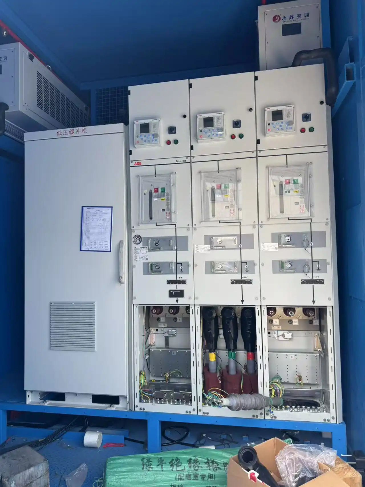
In one 630 kVA configuration, the equipment chain included a frequency converter, isolation transformer, metering equipment, high-voltage switchgear, low-voltage switchgear and several berth-side connection points.
A separate 500 kVA mobile configuration used an incoming ring-main unit, outgoing low-voltage switchgear, an isolation transformer and berth connection equipment.
The important difference was not 500 kVA versus 630 kVA.
The two systems used different electrical architectures.
Capacity alone does not determine:
- whether the incoming section is high or low voltage;
- where the transformer is located;
- whether a ring-main arrangement is appropriate;
- how many outgoing feeders are required;
- how the berth interface is arranged;
- where protection and metering boundaries sit.
Switchgear architecture follows the topology.
The single-line diagram should therefore be defined before the switchgear lineup is frozen.
For the wider equipment chain, see our shore power system architecture and components guide.
HV and LV Are Different Equipment Scopes
“Shore power switchgear” is a system role, not a single voltage-class product category.
A 10 kV incoming cabinet and a 400 or 440 V output board may belong to the same shore power system, but they do not belong to the same equipment scope.
IEC/IEEE 80005-1 addresses high-voltage shore connection systems, while IEC/IEEE 80005-3:2025 separately defines the scope for low-voltage shore connection systems.
For AC metal-enclosed switchgear above 1 kV and up to 52 kV, IEC 62271-200 provides the relevant high-voltage equipment framework. That scope should not be transferred automatically to a 400 or 440 V switchboard.
Define the voltage class and system position first, then define the applicable switchgear requirements.
Incoming Switchgear Defines the Port-Grid Interface
Incoming switchgear forms the electrical boundary between the port distribution network and the shore power equipment.
Its duties may include:
- switching and isolation;
- fault protection;
- current and voltage measurement;
- coordination with upstream protection;
- local and remote operation.
The incoming section is tied to the actual port network, so its fault duty cannot be inferred from converter capacity alone.
Project example: In one 10 kV shore power configuration, the incoming switchgear was specified for a rated current of at least 630 A and a short-time withstand requirement of 31.5 kA for four seconds.
Those values belonged to that network and that equipment position. They should not be copied into another project simply because the converter capacity is similar.
A different port supply can produce a different fault duty even when the converter rating is unchanged.
The incoming breaker must also coordinate with the upstream system.
In one configuration, the incoming breaker used overcurrent and earth-fault protection.
The objective is not to maximize the breaker rating. It is to match the switchgear duty to the actual network and coordinate the protection correctly.
Output Switchgear Protects a Different Electrical Interface
The output section faces a different electrical problem.
Depending on the system architecture, it may sit between:
- the frequency converter and transformer;
- the transformer and berth feeder;
- the converter and berth feeder;
- the berth connection equipment and vessel system.
The abnormal conditions seen by the outgoing feeder can therefore differ from those at the port-grid interface.
In one project, the outgoing protection included:
- overcurrent;
- overvoltage;
- undervoltage;
- earth fault;
- reverse power;
- unbalance.
The incoming section in the same project did not simply use the same protection list.
This does not mean every output feeder requires all of these functions.
Protection functions should be selected from the abnormal conditions that can actually occur at that system position, not from the number of relay functions available.
Adding protection functions also adds settings, coordination work and another possible source of unwanted trips.
Transfer Philosophy Can Change the Protection Problem
Reverse power is one example.
With a break-before-make transfer, the vessel source and shore source are not intentionally paralleled.
A controlled closed-transition sequence creates a different operating condition. Shore power and the vessel generator may temporarily operate together, so active-power direction becomes relevant to protection and control.
In one configuration, reverse-power behaviour formed part of the parallel-transfer logic, and excessive reverse power could lead to output-breaker protection action.
That does not make reverse-power protection a universal output-switchgear requirement.
It makes transfer philosophy an input to the protection design.
For the detailed control behaviour, see our shore power reverse power protection article.
Short-Circuit Duty Is a Location-Specific Requirement
Rated power and short-circuit duty answer different engineering questions.
Rated power describes how much load the system is intended to supply.
Short-circuit duty describes the electrical stress equipment may have to withstand during a fault.
Available fault current depends on the electrical source and the impedance between that source and the fault location.
Relevant points can include:
- port supply connection;
- converter input;
- transformer terminals;
- converter output;
- berth feeder;
- vessel connection.
Transformers and power-electronic converters can make downstream fault behaviour materially different from the upstream network.
Breaker and busbar ratings should therefore be checked at their actual locations rather than inferred from converter kVA.
A higher short-circuit rating can add equipment size and cost, but it does not correct an inaccurate fault study or poor protection coordination.
The engineering sequence is:
- define the system topology;
- establish the fault level at the relevant point;
- compare the calculated duty with the equipment rating;
- confirm protection coordination.
For the calculation inputs and boundaries, see our shore power short-circuit current calculation guide.
Why Interlocks Extend Beyond the Switchgear Cabinet
Shore power switching is not a single breaker operation.
The system moves through several physical and electrical states:
- disconnected;
- connected but de-energized;
- ready for energization;
- energized;
- transfer;
- isolated;
- maintenance;
- disconnection.
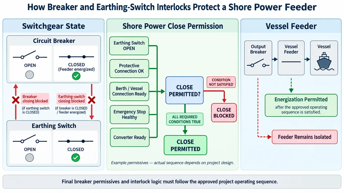
A breaker can be mechanically healthy while the complete shore-to-ship connection is still in an unsafe state.
The Problem Is an Unsafe Combination of States
Consider a feeder that has been earthed for maintenance while the circuit breaker remains available to close.
Each device may be functioning correctly on its own.
The combination is not acceptable.
Closing the breaker onto an earthed circuit must be prevented.
The reverse condition also matters. An earthing switch should not be allowed to earth an energized feeder.
The same principle applies to withdrawable breaker positions, compartment access and shore connection equipment.
The engineering problem is not necessarily a faulty component. It can be an invalid combination of otherwise valid component states.
Internal Switchgear Interlocks
In one project specification, interlocks were used to prevent:
- moving a breaker truck while carrying load;
- incorrect breaker operation;
- racking the breaker while the earthing switch was closed;
- access to an energized compartment;
- closing an earthing switch onto an energized circuit.
The earthing switch also had to provide a clearly defined open or closed state.
These functions turn the switching sequence into equipment behaviour rather than leaving the sequence only to operator memory.
System Permissives Can Extend to the Connection Equipment
The safe state of a shore power system does not stop at the switchgear door.
In one project, the cable plug was interlocked with the outgoing breaker, and the connection-box door was also linked to breaker permission.
The switchgear has its own mechanical and electrical interlocks.
The complete shore power system can add another permissive layer based on connection-equipment state and the approved operating sequence.
IEC/IEEE 80005-1 also treats interlocking within the wider high-voltage ship-shore connection system. EMSA guidance addresses shore-side electricity as a combined infrastructure, operational and safety problem.
More interlocking is not automatically better.
Additional permissives mean more signals, wiring, logic, commissioning and troubleshooting.
The design should distinguish safety-critical interlocks from operating permissives and alarm-only conditions. This keeps blocking logic aligned with the actual hazard and operating sequence.
Grounding Changes the Earth-Fault Problem
Output protection cannot be finalized before the neutral and grounding arrangement is understood.
Grounding determines the path available to earth-fault current.
Change that path and several protection conditions can change:
- fault-current magnitude;
- detection method;
- required measurement;
- relay function;
- trip philosophy.
In one shore power configuration, repeated cable movement and mechanical stress were considered relevant to earth-fault risk.
For the particular ungrounded arrangement described in that configuration, a single-phase earth fault could be difficult to detect and isolate quickly.
The system used a neutral grounding resistor together with zero-sequence protection at the output side.
That arrangement addressed the earth-fault detection problem in that configuration, but it is not a universal shore-power grounding method.
A different transformer connection or vessel-side neutral arrangement may require a different approach.
Define the grounding philosophy before finalizing earth-fault detection and output protection.
The final arrangement should be reviewed against both the shore and vessel single-line diagrams.
For the wider grounding and protective-earth problem, see our shore power equipotential bonding and grounding guide.
Metering, CT/PT and Control Interfaces Must Match Their Functions
Switchgear is also a measurement and control interface.
A common specification problem is selecting devices before the purpose of each measurement or signal has been defined.
In one shore power configuration, the system measured:
- current;
- voltage;
- frequency;
- active power;
- reactive power;
- power factor;
- active energy;
- reactive energy.
Those measurements can serve different purposes.
A protection relay, operator display and billing meter do not necessarily require the same measurement performance.
CT/PT Selection Follows the Function
Current-transformer selection should consider:
- ratio;
- accuracy;
- burden;
- connected relay or instrument.
The CT is therefore not an accessory that can be finalized independently after the protection design.
Voltage transformers follow the same principle.
Their arrangement and primary-side protection have to be coordinated with the measurement and protection functions they support.
Operating Measurement Is Not Automatically Billing Measurement
A switchgear display can show energy without the measurement automatically becoming suitable for commercial settlement.
Where billing is required, the project should separately define:
- commercial metering boundary;
- CT/PT accuracy;
- verification or certification requirements;
- applicable local utility requirements.
This prevents an operational measurement from being used for a purpose it was never specified to serve.
A Protocol Name Does Not Define the Control Interface
Writing only Modbus required or IEC 61850 required does not define the complete interface.
A network link can be healthy while the operating interface is still incomplete.
The project still needs to define:
- measurements;
- breaker positions;
- earthing-switch states;
- alarms;
- trips;
- permitted commands;
- command authority;
- permissive status;
- point list.
In one project specification, Modbus RTU or another open bus was permitted.
A separate 10 kV configuration used IEC 61850 as part of supervisory integration.
These are project implementations, not universal shore-power protocol requirements.
IEC/IEEE 80005-2 covers data interfaces and communication procedures for non-emergency monitoring and control functions. It does not specify communication for the emergency functions addressed by IEC/IEEE 80005-1.
A protocol defines how data can be exchanged.
It does not, by itself, define who is allowed to operate a breaker or under which conditions a command should be accepted.
Local and Remote Authority Must Be Explicit
Remote operation adds another control-authority boundary.
In one switchgear configuration, the low-voltage compartment included:
- protection relays;
- instruments and display;
- live indication;
- local/remote selection;
- fault reset.
A separate 10 kV configuration used motorized switchgear integrated with the supervisory system.
Operating authority can therefore exist both in the cabinet and in the higher-level control system.
The project needs to define:
- who is allowed to issue a command;
- which permissives still apply in remote mode;
- which actions must remain local;
- which status must be confirmed before a command is accepted.
Remote control should not bypass the safety logic that applies locally.
More remote capability also introduces more interface responsibility.
Additional commands require:
- authority management;
- communication testing;
- clear fallback behaviour;
- commissioning of the complete command-and-feedback path.
Condition monitoring can add another layer.
In one configuration, breaker operating-current curves, mechanism travel information and temperature data were used to assess equipment condition.
That is a project-specific monitoring approach, not a mandatory shore-power feature.
FAT Must Prove the Complete Switching Chain
Factory testing should do more than prove that a breaker can open and close.
A component can pass while the complete protection and control chain is still wrong.
For example:
- the correct relay may operate but the wrong breaker receives the trip;
- the breaker may move but the supervisory feedback remains incorrect;
- an interlock may exist in the drawing but fail to block the real command;
- an indication may show the wrong state;
- a withstand test may include equipment that should have been isolated.
Switchgear FAT therefore needs both electrical tests and functional verification.
Component PASS Does Not Equal System PASS
Functional verification should confirm whether the complete system reaches the intended final state when a protection or control condition occurs.
Testing components separately is not enough to prove that complete behaviour.
The Test Boundary Must Be Correct
In one project test procedure, preparation for main-circuit withstand testing included actions involving:
- PT circuits;
- incoming and outgoing cables;
- surge arresters where applicable;
- breaker test state.
The main circuit was then tested between phases and from phase to earth.
A correct test result starts with a correctly defined test boundary.
The wrong boundary can expose connected equipment to an inappropriate test condition or make the result difficult to interpret.
Functional Verification Must Follow the Action Chain
Each link has to be correct.
Testing only the first or last item does not prove the chain.
Interlocks and Secondary Circuits Need Functional Tests
The same project test procedure also included checks involving:
- breaker resistance;
- door and interlock functions;
- secondary wiring;
- wiring identification;
- continuity;
- control power;
- cabinet indications;
- communication between control devices.
These tests can reveal interface errors that are not visible in isolated component checks.
A complete FAT requires more preparation and test time than a simple component check. The benefit is that interface verification takes place before berth commissioning.
For the wider inspection and acceptance process, see our shore power manufacturing and FAT guide.
Common Shore Power Switchgear Specification Errors
Selecting Fault Duty from Converter kVA
Rated power and fault duty are different electrical quantities.
Confirm the available short-circuit level at the switchgear location.
Copying Incoming Protection to the Output Side
Incoming and outgoing sections sit at different interfaces.
Define protection from the actual fault and operating scenarios at each position.
Treating Interlocks as Cabinet-Only Functions
Breaker permission may depend on valid conditions in the connection equipment and the wider shore-to-ship sequence.
Define the complete permissive chain.
Finalizing Output Protection Before Grounding Is Defined
Grounding changes the earth-fault path.
The protection scheme cannot be finalized correctly while the neutral and grounding arrangement remains open.
Specifying a Communication Protocol Without Defining Authority and Data
A protocol is only part of the interface.
Define points, commands, permissives, operating authority and feedback as well.
What Must Be Defined Before Switchgear Selection
A useful switchgear RFQ needs more than voltage and converter capacity.
Electrical Data
Provide:
- incoming voltage and frequency;
- output voltage and frequency;
- normal and maximum operating current;
- available short-circuit level.
System Architecture
Provide:
- shore single-line diagram;
- vessel-side single-line diagram;
- converter arrangement;
- transformer ratings and impedances;
- feeder arrangement;
- number of berth or vessel connections.
Protection
Define:
- incoming protection philosophy;
- output protection philosophy;
- upstream/downstream coordination;
- transfer method;
- whether temporary parallel operation is allowed.
Grounding
Define:
- transformer connection;
- neutral arrangement;
- shore-side grounding method;
- vessel-side grounding information;
- earth-fault detection philosophy.
Metering
Define:
- operating measurements;
- billing requirements, if any;
- CT/PT accuracy requirements;
- metering boundary.
Control and Communication
Define:
- local operating mode;
- remote operating mode;
- command authority;
- breaker permissives;
- communication protocol;
- point list;
- alarm and trip responsibilities.
Verification and Compliance
Define:
- applicable HV or LV shore-connection framework;
- applicable switchgear equipment requirements;
- FAT scope;
- functional-test expectations;
- witness requirements;
- acceptance criteria.
These inputs allow the switchgear to be reviewed as part of the complete shore power system rather than as a catalogue item.
Frequently Asked Questions
Can incoming and output switchgear use the same rating?
Not automatically.
They may be at different voltage levels and different electrical positions. Rated current, fault duty and protection requirements should be checked separately.
Can short-circuit rating be selected from converter kVA?
No.
Converter kVA defines rated power transfer. Short-circuit duty depends on the actual source, impedance and equipment location.
Does every output switchgear need reverse-power protection?
No.
It depends on the transfer philosophy and whether shore and vessel sources are permitted to operate in parallel.
Does every shore power system need a neutral grounding resistor?
No.
An NGR was used in one configuration, but the correct grounding arrangement depends on transformer connections, neutral availability, vessel interface and earth-fault philosophy.
Can shore power switchgear be operated remotely?
Yes, when the equipment and control architecture are designed for remote operation.
The project still needs to define local/remote authority, permissives, command conditions and feedback.
Is specifying Modbus or IEC 61850 enough?
No.
The protocol does not define the complete point list, command authority, permissives, alarm responsibility or operating sequence.
Is correct converter voltage enough to permit vessel-feeder closing?
Not necessarily.
The electrical output may be correct while the switchgear, earthing or connection-equipment state still prevents safe energization.
Technical References
Specify the Complete Switchgear Interface
Switchgear selection should start from the electrical system and operating sequence, not from a cabinet catalogue.
For an engineering review, provide:
- shore and vessel single-line diagrams;
- available short-circuit data;
- transformer information;
- feeder arrangement;
- grounding method;
- transfer philosophy;
- protection requirements;
- control and metering interfaces;
- FAT and acceptance requirements.
With those inputs, the incoming and output switchgear can be reviewed against the actual shore-to-ship power path and operating sequence.
Send Your Project Requirements