
How to Specify a Shore Power Connection Box
A shore power connection box is the final berth-side interface between the shore power system and the vessel.
It should not be specified from system kVA and voltage alone.
Before manufacturing starts, the project team needs to know how the vessel will connect, how much current the interface must carry, which protective and pilot circuits are required, where the box will be installed, how the cable will approach it, how connection status will be confirmed, and how those conditions interact with the shore-side breaker.
A shore power source can have the correct voltage and capacity and still be difficult—or unsafe—to connect if these interface conditions are left unresolved.
Why a Connection Box Is More Than an Outdoor Socket
The engineering problem is not simply how to install sockets inside a weather-resistant enclosure.
The connection box has to form a compatible electrical, protective, control and mechanical interface between a fixed shore installation and a vessel-side cable system.
That is why shore-connection standards treat the interface as more than a set of phase contacts. IEC/IEEE 80005-3:2025 covers low-voltage shore-to-ship connection and interface equipment together with protection, control, monitoring, interlocking and power-management functions within its defined LVSC scope.
EMSA similarly treats the ship-shore interface as a distinct part of shore-side electricity infrastructure between berth-side equipment and the receiving ship.
For specification purposes, the connection box therefore sits at the point where several engineering questions meet:
- Can the vessel cable physically reach and approach the connection point?
- Are the connector voltage and current ratings correct?
- Is the protective connection established?
- Are the required pilot or permissive conditions available?
- Can the system distinguish connection state from emergency state?
- Can personnel connect and disconnect the interface without exposure to an energized condition?
- Can the connection be inspected and verified before energization?
A specification that answers only the enclosure size, IP rating and total kVA leaves most of these questions unresolved.
Start with the Vessel Interface
Define the vessel side before fixing the berth-side box.
The basic inputs are:
- connection voltage and frequency
- maximum demand or continuous current
- vessel-side connector arrangement
- number of power cables or parallel connectors
- cable size and handling method
- vessel connection-point location
- protective-earth and pilot requirements
- communication requirements, if any
A request for “one shore power socket box” is not enough for engineering.
Two vessels with similar power demand can still require different berth equipment if their connector arrangement, cable system or connection position is different.
The box also has to match the equipment immediately upstream and downstream. On the shore side, that includes the output cable and switchgear. On the vessel side, the connection may interface with a cable reel, plug assembly and vessel distribution system.
For that wider relationship, see our shore power system architecture and components .
Convert Capacity into Actual Connector Current
System capacity and connector capacity are related, but they are not the same design input.
Total kVA describes the power requirement of the source. The physical connection has to carry the actual current flowing through each cable and connector at the selected connection voltage.
A source can therefore be correctly sized in kVA while the physical connector arrangement is still unsuitable for the vessel.
First determine the current at the required connection voltage. Then review that current together with:
- connector rating
- vessel cable rating
- number of parallel connectors
- continuous operating duty
- vessel-side cable arrangement
This becomes especially important at low voltage because relatively moderate system capacity can still produce high connection current.
IEC/IEEE 80005-3:2025 defines its LVSC scope using several interface conditions rather than system power alone. It applies to three-phase systems rated 250 A and above, with nominal voltages from 400 V AC to 1,000 V AC, for ships requiring up to 1 MVA at berth.
In one low-voltage berth project, 250 A and 350 A shore connectors were used, with the number of sockets selected for the required output arrangement.
Connector rating and quantity should therefore be selected from the actual vessel current and cable arrangement rather than copied from another project.
Cable length and voltage drop should also be checked when the box position is selected, particularly on high-current low-voltage connections.
Define Power, Protective Earth and Pilot Interfaces Together
The presence of shore voltage does not prove that the ship-to-shore interface is ready to be energized.
The vessel connection is more than three power conductors.
Depending on the selected connector system, the interface can also include:
- protective earth
- pilot contacts
- connection-status circuits
- safety-permissive circuits
- communication contacts or fiber
These functions represent different conditions.
The power contacts carry energy.
The protective-earth path forms part of the protective connection between shore and vessel.
Pilot or permissive circuits can provide information about whether the required connection condition has been established.
Communication links can serve monitoring or control functions, but they do not automatically replace protective or emergency circuits.
Within the scope of IEC 60309-5:2017, the specified LVSC accessory includes an earth contact and four pilot contacts, illustrating that the standardized low-voltage shore interface includes functions beyond the phase conductors. This should not be generalized to every connector architecture outside that standard's scope.
The exact contact arrangement therefore needs to follow the selected connector system and vessel interface. Copying the pin or pilot arrangement from another project without checking compatibility can create problems during commissioning.
In one shore-to-ship procedure, the cable connection was followed by a joint safety-circuit test involving the shore power room, berth-side team and vessel electrical team.
Pilot and permissive circuits therefore need to be testable across the complete ship-to-shore interface.
For a deeper explanation of protective earth, equipotential bonding and pilot permissives, see shore power equipotential bonding and grounding .

Coordinate the Connection Box with the Output Breaker
The connection box and upstream output breaker should be treated as one operating interface.
The design question is not simply whether the breaker can close.
It is whether the required ship-to-shore connection conditions have been proven before energization is permitted.
Depending on the project, relevant conditions can include:
- plug position
- pilot status
- box-door status
- protective-earth or grounding status
- emergency stop
- breaker closing permissive
In one berth project, both the cable plug and the connection-box door were interlocked with the shore output breaker.
Status signals should also remain specific.
One shore power monitoring configuration separated connection-box information into cable connection ready, emergency disconnect and grounding status. Additional monitoring included energized indication, fault and box-door status.
Physical connector position, electrical readiness, grounding status and emergency state do not prove the same condition.
Keeping these states distinguishable makes commissioning and fault diagnosis clearer than reducing them to one generic “box ready” signal.
Whether the switching device is inside the connection equipment or located upstream depends on the system architecture. The connection status and breaker permissive still need to be designed together.
What Past Shore-Power Incidents Reveal
Historical incidents help explain why connection status, isolation and connector design cannot be treated as secondary details.
An Energized Connector Can Become a Direct Personnel Hazard
In 1997, Transport Canada issued a shore-power electrical-shock safety bulletin after a crew member on a Canadian-registered vessel received a 480 V shock.
The shore-power cable was connected to the source on shore, while the free end lay on the vessel deck. The worker picked up the male plug and came into contact with exposed energized pins.
Transport Canada identified two contributing factors: maintenance was being attempted on an energized system, and the shore-power arrangement left energized male plug terminals exposed and accessible.
The engineering relevance goes beyond that particular connector arrangement. A shore-power interface has to control not only voltage and current rating, but also when conductive parts can become energized and under what conditions personnel can handle the connection.
“Breaker Off” Is Not the Same as “Proven Dead”
A 2025 IMCA Safety Flash described a different shore-power incident.
A vessel Electro-Technical Officer reportedly switched off the quayside breaker and then disconnected the shore cable from the vessel connection box. During removal, the shore-side cable appeared still to be energized and an electrical arc occurred, causing light burn injuries to the eyes.
IMCA's preliminary findings pointed to inadequate communication and documentation between the vessel and quayside shore-power provider. Its safety lesson was explicit: power should not be assumed to be off; the electrical condition should be checked with an appropriate tester and isolated before the cable is considered safe.
A breaker may have been commanded open. A status may indicate a particular state. Personnel still need the verification required by the approved operating and isolation procedure before handling the interface.
Why Interlocks and Permissives Exist
High-voltage shore-connection guidance provides a useful example of this safety principle.
The ABS Guide for High Voltage Shore Connection requires, within its HVSC scope, arrangements that prevent closing the shore connection circuit breaker when required interface conditions are not established. Its provisions address conditions including equipotential bonding, pilot circuits and emergency shutdown, as well as attempts to disengage a high-voltage plug while energized.
These are high-voltage-specific requirements and should not be copied directly into every low-voltage connection-box design.
The required connection conditions have to be defined for the applicable voltage level, connector system, class requirements and operating architecture.
That principle is consistent with the real berth project described above, where plug position and box-door condition were interlocked with the shore output breaker.
The interlock is therefore not a decorative control feature. It is part of the boundary between a physical connection that exists and a connection that has been proven ready for energized operation.
Specify the Enclosure from the Actual Berth Environment
An IP rating is only one part of the enclosure specification.
A berth-side connection box may be exposed to:
- rain
- salt-laden air
- humidity
- condensation
- dust
- corrosion
These conditions matter not only because the enclosure has to survive outdoors.
They can also affect the quality of the electrical connection.
Connector oxidation, aging and poor contact condition can increase connection resistance. Internal operating and maintenance procedures therefore call for maintenance of shore sockets, vessel plugs and sockets, and cable-reel slip-ring paths, as well as replacement of connection equipment when contact resistance becomes unacceptable.
Environmental design, connector condition and maintenance access are therefore related.
Check the actual site conditions before fixing:
- enclosure material
- surface protection
- seals and cable glands
- drainage
- condensation control
- ingress protection
- maintenance access
One outdoor berth project used a 304 stainless-steel enclosure, IP65 protection and enclosure heating for its site conditions.
Another berth may require a different material or protection level. The decision should follow the actual corrosion exposure, installation position, moisture conditions and maintenance environment rather than a copied specification.
For the corrosion and salt-fog conditions behind these enclosure decisions, see our shore power corrosion and salt-fog protection article.
Position, Orientation and Cable Approach Must Work Together
A convenient electrical location is not automatically a good operating location.
The final position needs to work with:
- the vessel connection point
- cable reach
- cable approach direction
- cable bending and tension
- operator working space
- mooring lines
- berth traffic
- cargo operations
- maintenance access
Real connection work involves more than checking whether the cable can physically reach the box.
In one berth procedure, the vessel cable and plug were pulled to the connection box with a hauling line. The shore team then left suitable cable slack, inserted the plug and mechanically secured the plug and cable before connection checks continued.
Poor connector orientation or insufficient working slack can transfer unnecessary mechanical load into the cable and plug instead of allowing the cable-handling arrangement to accommodate the connection geometry.
The cable needs a practical route into the connector. It also needs enough slack to avoid transferring unnecessary force to the plug while still allowing the cable to be restrained after connection.
A box can therefore be close enough in plan view but still be difficult to operate if:
- the connector faces the wrong direction
- the cable must turn sharply
- the cable crosses an operating route
- there is not enough room to pull and secure the cable
- the door or connector face conflicts with berth operations
In one berth project, the connection-box location was required to account for berth layout, vessel characteristics and mooring operation.
Box position should therefore be confirmed from the actual berth drawing and vessel connection geometry before civil and electrical installation details are frozen.
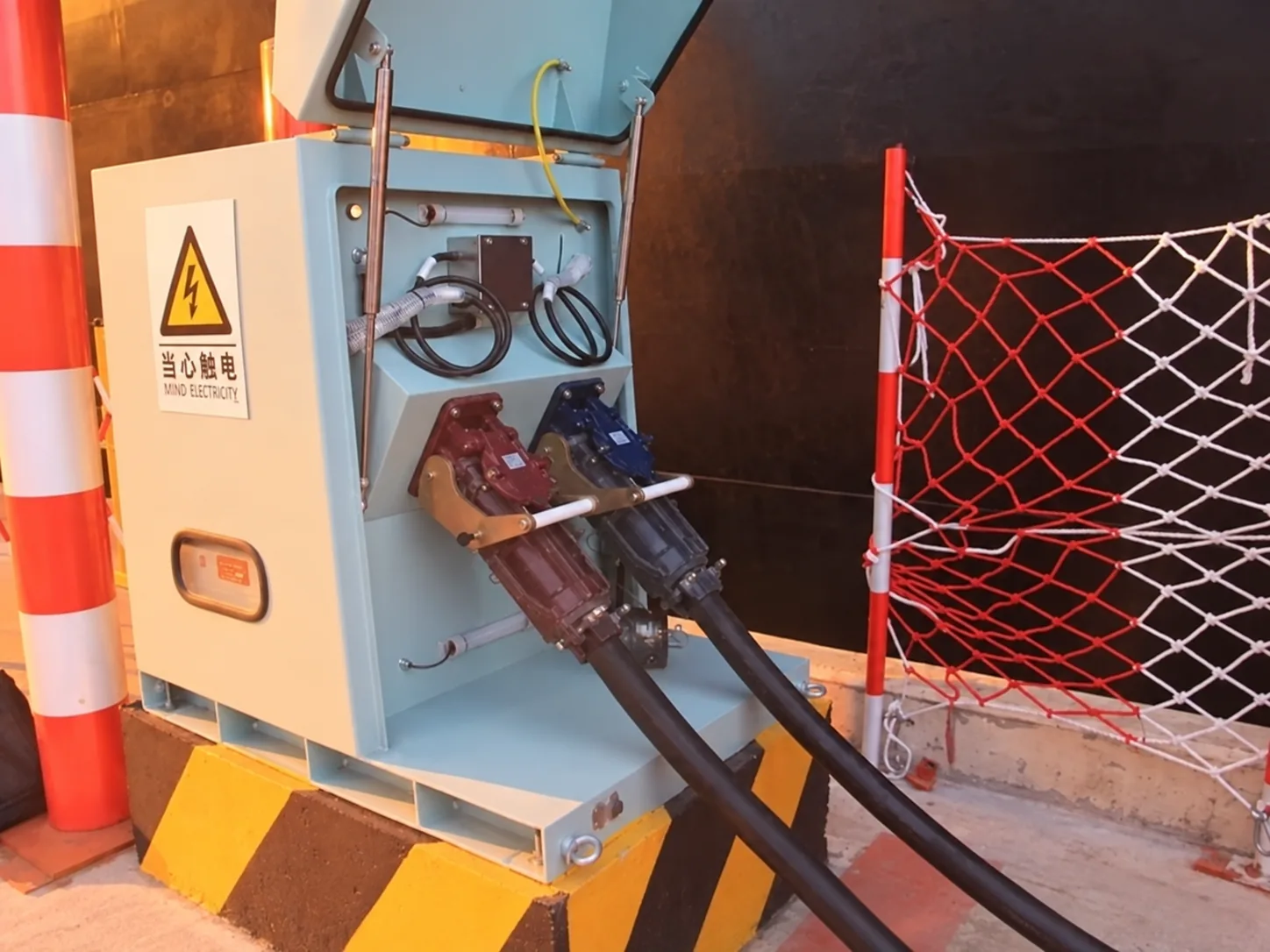
More Connection Points Do Not Automatically Mean More Capacity
The number of berth connection points and the available shore power capacity are different design questions.
In one 630 kVA berth configuration, three berth-front socket boxes formed the ship-to-shore connection system.
In a separate 5 MVA, 6.6 kV installation, each shore power source fed two berth connection boxes so the vessel could connect from different positions along the berth.
These configurations used different voltage levels, capacities and physical arrangements, but the same design principle applies:
Additional boxes may increase the number of usable connection positions. They do not automatically create additional converter or transformer capacity.
For a new project, distinguish between:
- number of physical connection positions
- number of vessels that may use those positions
- number of vessels that must be supplied simultaneously
- capacity available from each upstream source
Without that distinction, adding more boxes can be mistaken for adding more electrical capacity.
Define Communication and Cable-Reel Interfaces Explicitly
Communication availability and safety permissive are not the same requirement.
Depending on the project scope, the connection box may need interfaces with the vessel, cable reel, local control system or port monitoring system.
If communication is required, define the scope before manufacturing.
At minimum, clarify:
- fiber or electrical communication requirement
- connector and termination responsibility
- required status signals
- cable-reel interface
- testing responsibility
In one berth specification, the connection box included a fiber interface to the ship-to-shore cable system.
In a shore power monitoring configuration, connection-ready, emergency and grounding states were monitored separately, while the cable reel provided payout and retraction signals.
The connection box and cable-handling equipment therefore cannot always be specified independently when their states are part of the shore power operating sequence.
A useful interface schedule should distinguish:
- physical connection status
- electrical readiness
- grounding or protective status
- emergency status
- cable-reel status
- communication health, where required
IEC/IEEE 80005-2:2016 reinforces an important functional boundary. Its scope covers shore/ship data communication for monitoring and control of non-emergency functions, where required, while excluding communication for emergency functions defined elsewhere in the 80005 framework.
A fiber or data link may therefore support monitoring and control, but the project still has to define separately how safety permissives and emergency functions are implemented.
“Communication interface provided” is not a complete specification.
A reserved opening does not confirm the connector, signal list, termination, safety function or functional test.
Define What Must Be Verified Before Energization
The connection box should make the required pre-energization checks physically possible.
In one shore-to-ship procedure, the cable and plugs had to be securely connected, the connection resistance had to be acceptable, and the safety circuit was then tested before the operating sequence continued.
Relevant berth-interface checks may include:
- correct plug engagement
- cable restraint
- protective connection
- pilot or permissive status
- emergency-stop function
- connection resistance
- communication status
- phase sequence, where applicable
An indication, command or verbal confirmation should not be treated as a substitute for the verification required by the approved operating procedure.
The specification therefore needs to answer:
Can the required connection conditions be inspected, measured or proven before the system is energized—or before personnel handle the connector during disconnection?
If not, the connection-box design and operating interface remain incomplete even if the electrical rating is correct.
For the wider shore-to-ship operating sequence, see our shore power connection procedure .
Design for Inspection and Maintenance
The connectors are repeatedly engaged and disengaged, while the box remains exposed to the berth environment.
Salt, moisture, contamination and repeated operation can affect the connection surfaces over time.
Shore power operating and maintenance procedures identify connector oxidation, aging and poor contact condition as problems that can increase connection resistance. The vessel-side plug, socket and cable-reel slip-ring path can also require inspection.
This creates a direct layout requirement.
Connector terminals and inspection points should remain accessible for:
- visual inspection
- cleaning
- resistance checks
- terminal tightening
- seal inspection
- component replacement
Do not arrange unrelated components so tightly around the connector section that routine inspection requires major disassembly.
The same principle applies to:
- cable glands
- enclosure heaters
- drainage points
- interlock components
- mechanical locks
Maintenance access is part of the original connection-box layout, not something to solve after commissioning.
Information to Include in the RFQ
A connection-box RFQ should give the supplier enough information to review the complete vessel interface.
Electrical
- connection voltage and frequency
- required capacity or maximum current
- operating configuration
Connector and Cable
- vessel connector type or applicable standard
- number of connectors
- cable quantity and size
- cable length or required reach
- cable-reel or cable-handling method
Mechanical Connection
- vessel connection-point position
- cable approach direction
- required working slack
- cable restraint method
- proposed box position and orientation
- working clearance
Safety Interface
- protective-earth arrangement
- pilot requirements
- required connection permissives
- emergency-stop action
- upstream breaker interface
- isolation and prove-dead procedure where applicable
Status and Communication
- connection-ready signals
- grounding or protective status
- emergency status
- breaker status required at the interface
- cable-reel signals
- fiber or communication requirement
- termination responsibility
- separation between monitoring communication and safety functions
Environment
- temperature and humidity
- salt, rain and dust exposure
- condensation or flood risk
- any specified enclosure requirement
Verification
- plug engagement checks
- connection-resistance requirement
- pilot or permissive test
- emergency-stop test
- status-signal test
- electrical-isolation verification before handling, where required by the operating procedure
Project Interface
- applicable standards
- class requirements
- responsibility boundary between shore, vessel and equipment supplier
- responsibility for connection, energization, isolation and disconnection
With these inputs, the connection box can be reviewed as part of the complete ship-to-shore interface rather than treated as an isolated outdoor cabinet.
Frequently Asked Questions
Can a shore power connection box be selected from kVA alone?
No. Voltage, actual current, connector rating, number of parallel connectors, cable arrangement and vessel interface also have to be confirmed.
Does every connection box need its own circuit breaker?
Not necessarily. Switching equipment may be integrated into the connection equipment, or the box may be interlocked with an upstream output breaker. The final arrangement depends on the project electrical architecture.
Is IP65 enough for every berth-side connection box?
Not automatically. Ingress protection is only one part of the environmental design. Material, salt exposure, condensation, drainage, flooding, sealing and maintenance conditions also need to be reviewed.
What does the pilot circuit do?
It can provide connection-status or safety-permissive information. The exact contact arrangement and logic depend on the selected connector and vessel interface.
Is a breaker “OFF” indication enough before disconnecting a shore cable?
Not by itself. The operating procedure should define what verifies electrical isolation at the point where the cable will be handled. A command, indication and actual electrical condition should not be assumed to be equivalent.
Is the communication link also the safety interlock?
Not necessarily. Monitoring/control communication and safety or emergency functions can belong to different functional layers. Their responsibilities and interfaces should be defined separately for the selected system architecture.
Why does connection-box location matter?
Because it affects cable reach, cable approach, working slack, cable restraint, connector loading, operator access and possible interference with mooring and berth operations.
References
Incident References
Technical References
- IEC/IEEE 80005-3:2025 — Utility Connections in Port — Part 3: Low-Voltage Shore Connection Systems
- IEC/IEEE 80005-2:2016 — Data Communication for Monitoring and Control
- IEC 60309-5:2017 — LV Shore Connection Plugs, Socket-Outlets and Couplers
- American Bureau of Shipping — Guide for High Voltage Shore Connection, July 2021
- European Maritime Safety Agency — Guidance on Shore-Side Electricity to Port Authorities and Administrations
Specify the Berth Interface Before Manufacturing
Before the connection box is manufactured, define the vessel voltage and frequency, required current or capacity, connector and cable arrangement, berth layout, cable approach, protective-earth and pilot requirements, interlock philosophy, status signals, environmental conditions, communication scope and verification method.
Do not stop at asking whether the box has the correct voltage, current rating and IP level.
The final specification should also answer:
- What proves that the vessel interface is correctly connected?
- What prevents energization when the required conditions are incomplete?
- What proves electrical isolation before the connector is handled?
- Which states are safety-critical and which are monitoring information?
- What physical cable geometry must the box accommodate?
- What inspection and maintenance tasks must remain accessible?
SDACME can review these interface conditions together with the upstream switchgear and overall shore power architecture.
Send Project Requirements